EP1407521B1 - Line narrowing unit with flexural grating mount - Google Patents
Line narrowing unit with flexural grating mount Download PDFInfo
- Publication number
- EP1407521B1 EP1407521B1 EP02744246A EP02744246A EP1407521B1 EP 1407521 B1 EP1407521 B1 EP 1407521B1 EP 02744246 A EP02744246 A EP 02744246A EP 02744246 A EP02744246 A EP 02744246A EP 1407521 B1 EP1407521 B1 EP 1407521B1
- Authority
- EP
- European Patent Office
- Prior art keywords
- grating
- mount
- purge gas
- joint
- face
- Prior art date
- Legal status (The legal status is an assumption and is not a legal conclusion. Google has not performed a legal analysis and makes no representation as to the accuracy of the status listed.)
- Expired - Lifetime
Links
- 239000000758 substrate Substances 0.000 claims abstract description 19
- 238000010926 purge Methods 0.000 claims description 39
- 239000000463 material Substances 0.000 claims description 7
- 239000002344 surface layer Substances 0.000 claims 5
- 239000010410 layer Substances 0.000 claims 1
- 229910052782 aluminium Inorganic materials 0.000 abstract description 13
- XAGFODPZIPBFFR-UHFFFAOYSA-N aluminium Chemical compound [Al] XAGFODPZIPBFFR-UHFFFAOYSA-N 0.000 abstract description 13
- 239000011521 glass Substances 0.000 abstract description 12
- 229910052751 metal Inorganic materials 0.000 abstract description 5
- 239000002184 metal Substances 0.000 abstract description 5
- 230000008602 contraction Effects 0.000 abstract description 3
- 239000007789 gas Substances 0.000 description 38
- IJGRMHOSHXDMSA-UHFFFAOYSA-N Atomic nitrogen Chemical compound N#N IJGRMHOSHXDMSA-UHFFFAOYSA-N 0.000 description 24
- 229910052757 nitrogen Inorganic materials 0.000 description 12
- 239000004593 Epoxy Substances 0.000 description 9
- 238000001459 lithography Methods 0.000 description 9
- 238000000034 method Methods 0.000 description 9
- 229910001374 Invar Inorganic materials 0.000 description 7
- 239000001307 helium Substances 0.000 description 7
- 229910052734 helium Inorganic materials 0.000 description 7
- SWQJXJOGLNCZEY-UHFFFAOYSA-N helium atom Chemical compound [He] SWQJXJOGLNCZEY-UHFFFAOYSA-N 0.000 description 7
- 230000035882 stress Effects 0.000 description 7
- 230000000694 effects Effects 0.000 description 6
- XKRFYHLGVUSROY-UHFFFAOYSA-N Argon Chemical compound [Ar] XKRFYHLGVUSROY-UHFFFAOYSA-N 0.000 description 4
- 230000002411 adverse Effects 0.000 description 4
- 238000013461 design Methods 0.000 description 4
- 230000003287 optical effect Effects 0.000 description 4
- PXGOKWXKJXAPGV-UHFFFAOYSA-N Fluorine Chemical compound FF PXGOKWXKJXAPGV-UHFFFAOYSA-N 0.000 description 3
- 230000004075 alteration Effects 0.000 description 3
- 230000004888 barrier function Effects 0.000 description 3
- 238000005452 bending Methods 0.000 description 3
- 239000011737 fluorine Substances 0.000 description 3
- 229910052731 fluorine Inorganic materials 0.000 description 3
- 238000004519 manufacturing process Methods 0.000 description 3
- 229910052754 neon Inorganic materials 0.000 description 3
- GKAOGPIIYCISHV-UHFFFAOYSA-N neon atom Chemical compound [Ne] GKAOGPIIYCISHV-UHFFFAOYSA-N 0.000 description 3
- 229910052786 argon Inorganic materials 0.000 description 2
- 230000006866 deterioration Effects 0.000 description 2
- 238000010438 heat treatment Methods 0.000 description 2
- 238000012986 modification Methods 0.000 description 2
- 230000004048 modification Effects 0.000 description 2
- 238000012360 testing method Methods 0.000 description 2
- 241001149900 Fusconaia subrotunda Species 0.000 description 1
- XUIMIQQOPSSXEZ-UHFFFAOYSA-N Silicon Chemical compound [Si] XUIMIQQOPSSXEZ-UHFFFAOYSA-N 0.000 description 1
- PNEYBMLMFCGWSK-UHFFFAOYSA-N aluminium oxide Inorganic materials [O-2].[O-2].[O-2].[Al+3].[Al+3] PNEYBMLMFCGWSK-UHFFFAOYSA-N 0.000 description 1
- 238000010420 art technique Methods 0.000 description 1
- QVGXLLKOCUKJST-UHFFFAOYSA-N atomic oxygen Chemical compound [O] QVGXLLKOCUKJST-UHFFFAOYSA-N 0.000 description 1
- 238000001816 cooling Methods 0.000 description 1
- 230000003247 decreasing effect Effects 0.000 description 1
- 238000011161 development Methods 0.000 description 1
- 238000010586 diagram Methods 0.000 description 1
- 238000009826 distribution Methods 0.000 description 1
- 229910052743 krypton Inorganic materials 0.000 description 1
- DNNSSWSSYDEUBZ-UHFFFAOYSA-N krypton atom Chemical compound [Kr] DNNSSWSSYDEUBZ-UHFFFAOYSA-N 0.000 description 1
- 238000001393 microlithography Methods 0.000 description 1
- 239000001301 oxygen Substances 0.000 description 1
- 229910052760 oxygen Inorganic materials 0.000 description 1
- 230000010363 phase shift Effects 0.000 description 1
- 230000005855 radiation Effects 0.000 description 1
- 230000009467 reduction Effects 0.000 description 1
- 229910052710 silicon Inorganic materials 0.000 description 1
- 239000010703 silicon Substances 0.000 description 1
- 230000008646 thermal stress Effects 0.000 description 1
- 238000012546 transfer Methods 0.000 description 1
- 210000000623 ulna Anatomy 0.000 description 1
Images







Classifications
-
- G—PHYSICS
- G02—OPTICS
- G02B—OPTICAL ELEMENTS, SYSTEMS OR APPARATUS
- G02B5/00—Optical elements other than lenses
- G02B5/04—Prisms
- G02B5/06—Fluid-filled or evacuated prisms
-
- H—ELECTRICITY
- H01—ELECTRIC ELEMENTS
- H01S—DEVICES USING THE PROCESS OF LIGHT AMPLIFICATION BY STIMULATED EMISSION OF RADIATION [LASER] TO AMPLIFY OR GENERATE LIGHT; DEVICES USING STIMULATED EMISSION OF ELECTROMAGNETIC RADIATION IN WAVE RANGES OTHER THAN OPTICAL
- H01S3/00—Lasers, i.e. devices using stimulated emission of electromagnetic radiation in the infrared, visible or ultraviolet wave range
- H01S3/02—Constructional details
- H01S3/03—Constructional details of gas laser discharge tubes
- H01S3/036—Means for obtaining or maintaining the desired gas pressure within the tube, e.g. by gettering, replenishing; Means for circulating the gas, e.g. for equalising the pressure within the tube
-
- G—PHYSICS
- G03—PHOTOGRAPHY; CINEMATOGRAPHY; ANALOGOUS TECHNIQUES USING WAVES OTHER THAN OPTICAL WAVES; ELECTROGRAPHY; HOLOGRAPHY
- G03F—PHOTOMECHANICAL PRODUCTION OF TEXTURED OR PATTERNED SURFACES, e.g. FOR PRINTING, FOR PROCESSING OF SEMICONDUCTOR DEVICES; MATERIALS THEREFOR; ORIGINALS THEREFOR; APPARATUS SPECIALLY ADAPTED THEREFOR
- G03F7/00—Photomechanical, e.g. photolithographic, production of textured or patterned surfaces, e.g. printing surfaces; Materials therefor, e.g. comprising photoresists; Apparatus specially adapted therefor
- G03F7/70—Microphotolithographic exposure; Apparatus therefor
- G03F7/70008—Production of exposure light, i.e. light sources
- G03F7/70025—Production of exposure light, i.e. light sources by lasers
-
- G—PHYSICS
- G03—PHOTOGRAPHY; CINEMATOGRAPHY; ANALOGOUS TECHNIQUES USING WAVES OTHER THAN OPTICAL WAVES; ELECTROGRAPHY; HOLOGRAPHY
- G03F—PHOTOMECHANICAL PRODUCTION OF TEXTURED OR PATTERNED SURFACES, e.g. FOR PRINTING, FOR PROCESSING OF SEMICONDUCTOR DEVICES; MATERIALS THEREFOR; ORIGINALS THEREFOR; APPARATUS SPECIALLY ADAPTED THEREFOR
- G03F7/00—Photomechanical, e.g. photolithographic, production of textured or patterned surfaces, e.g. printing surfaces; Materials therefor, e.g. comprising photoresists; Apparatus specially adapted therefor
- G03F7/70—Microphotolithographic exposure; Apparatus therefor
- G03F7/70483—Information management; Active and passive control; Testing; Wafer monitoring, e.g. pattern monitoring
- G03F7/7055—Exposure light control in all parts of the microlithographic apparatus, e.g. pulse length control or light interruption
- G03F7/70575—Wavelength control, e.g. control of bandwidth, multiple wavelength, selection of wavelength or matching of optical components to wavelength
-
- H—ELECTRICITY
- H01—ELECTRIC ELEMENTS
- H01S—DEVICES USING THE PROCESS OF LIGHT AMPLIFICATION BY STIMULATED EMISSION OF RADIATION [LASER] TO AMPLIFY OR GENERATE LIGHT; DEVICES USING STIMULATED EMISSION OF ELECTROMAGNETIC RADIATION IN WAVE RANGES OTHER THAN OPTICAL
- H01S3/00—Lasers, i.e. devices using stimulated emission of electromagnetic radiation in the infrared, visible or ultraviolet wave range
- H01S3/02—Constructional details
- H01S3/04—Arrangements for thermal management
- H01S3/0401—Arrangements for thermal management of optical elements being part of laser resonator, e.g. windows, mirrors, lenses
-
- H—ELECTRICITY
- H01—ELECTRIC ELEMENTS
- H01S—DEVICES USING THE PROCESS OF LIGHT AMPLIFICATION BY STIMULATED EMISSION OF RADIATION [LASER] TO AMPLIFY OR GENERATE LIGHT; DEVICES USING STIMULATED EMISSION OF ELECTROMAGNETIC RADIATION IN WAVE RANGES OTHER THAN OPTICAL
- H01S3/00—Lasers, i.e. devices using stimulated emission of electromagnetic radiation in the infrared, visible or ultraviolet wave range
- H01S3/10—Controlling the intensity, frequency, phase, polarisation or direction of the emitted radiation, e.g. switching, gating, modulating or demodulating
- H01S3/13—Stabilisation of laser output parameters, e.g. frequency or amplitude
-
- H—ELECTRICITY
- H01—ELECTRIC ELEMENTS
- H01S—DEVICES USING THE PROCESS OF LIGHT AMPLIFICATION BY STIMULATED EMISSION OF RADIATION [LASER] TO AMPLIFY OR GENERATE LIGHT; DEVICES USING STIMULATED EMISSION OF ELECTROMAGNETIC RADIATION IN WAVE RANGES OTHER THAN OPTICAL
- H01S3/00—Lasers, i.e. devices using stimulated emission of electromagnetic radiation in the infrared, visible or ultraviolet wave range
- H01S3/14—Lasers, i.e. devices using stimulated emission of electromagnetic radiation in the infrared, visible or ultraviolet wave range characterised by the material used as the active medium
- H01S3/22—Gases
- H01S3/223—Gases the active gas being polyatomic, i.e. containing two or more atoms
- H01S3/225—Gases the active gas being polyatomic, i.e. containing two or more atoms comprising an excimer or exciplex
-
- H—ELECTRICITY
- H01—ELECTRIC ELEMENTS
- H01S—DEVICES USING THE PROCESS OF LIGHT AMPLIFICATION BY STIMULATED EMISSION OF RADIATION [LASER] TO AMPLIFY OR GENERATE LIGHT; DEVICES USING STIMULATED EMISSION OF ELECTROMAGNETIC RADIATION IN WAVE RANGES OTHER THAN OPTICAL
- H01S3/00—Lasers, i.e. devices using stimulated emission of electromagnetic radiation in the infrared, visible or ultraviolet wave range
- H01S3/02—Constructional details
-
- H—ELECTRICITY
- H01—ELECTRIC ELEMENTS
- H01S—DEVICES USING THE PROCESS OF LIGHT AMPLIFICATION BY STIMULATED EMISSION OF RADIATION [LASER] TO AMPLIFY OR GENERATE LIGHT; DEVICES USING STIMULATED EMISSION OF ELECTROMAGNETIC RADIATION IN WAVE RANGES OTHER THAN OPTICAL
- H01S3/00—Lasers, i.e. devices using stimulated emission of electromagnetic radiation in the infrared, visible or ultraviolet wave range
- H01S3/02—Constructional details
- H01S3/03—Constructional details of gas laser discharge tubes
-
- H—ELECTRICITY
- H01—ELECTRIC ELEMENTS
- H01S—DEVICES USING THE PROCESS OF LIGHT AMPLIFICATION BY STIMULATED EMISSION OF RADIATION [LASER] TO AMPLIFY OR GENERATE LIGHT; DEVICES USING STIMULATED EMISSION OF ELECTROMAGNETIC RADIATION IN WAVE RANGES OTHER THAN OPTICAL
- H01S3/00—Lasers, i.e. devices using stimulated emission of electromagnetic radiation in the infrared, visible or ultraviolet wave range
- H01S3/02—Constructional details
- H01S3/03—Constructional details of gas laser discharge tubes
- H01S3/034—Optical devices within, or forming part of, the tube, e.g. windows, mirrors
-
- H—ELECTRICITY
- H01—ELECTRIC ELEMENTS
- H01S—DEVICES USING THE PROCESS OF LIGHT AMPLIFICATION BY STIMULATED EMISSION OF RADIATION [LASER] TO AMPLIFY OR GENERATE LIGHT; DEVICES USING STIMULATED EMISSION OF ELECTROMAGNETIC RADIATION IN WAVE RANGES OTHER THAN OPTICAL
- H01S3/00—Lasers, i.e. devices using stimulated emission of electromagnetic radiation in the infrared, visible or ultraviolet wave range
- H01S3/05—Construction or shape of optical resonators; Accommodation of active medium therein; Shape of active medium
- H01S3/08—Construction or shape of optical resonators or components thereof
- H01S3/08004—Construction or shape of optical resonators or components thereof incorporating a dispersive element, e.g. a prism for wavelength selection
- H01S3/08009—Construction or shape of optical resonators or components thereof incorporating a dispersive element, e.g. a prism for wavelength selection using a diffraction grating
-
- H—ELECTRICITY
- H01—ELECTRIC ELEMENTS
- H01S—DEVICES USING THE PROCESS OF LIGHT AMPLIFICATION BY STIMULATED EMISSION OF RADIATION [LASER] TO AMPLIFY OR GENERATE LIGHT; DEVICES USING STIMULATED EMISSION OF ELECTROMAGNETIC RADIATION IN WAVE RANGES OTHER THAN OPTICAL
- H01S3/00—Lasers, i.e. devices using stimulated emission of electromagnetic radiation in the infrared, visible or ultraviolet wave range
- H01S3/05—Construction or shape of optical resonators; Accommodation of active medium therein; Shape of active medium
- H01S3/08—Construction or shape of optical resonators or components thereof
- H01S3/08059—Constructional details of the reflector, e.g. shape
-
- H—ELECTRICITY
- H01—ELECTRIC ELEMENTS
- H01S—DEVICES USING THE PROCESS OF LIGHT AMPLIFICATION BY STIMULATED EMISSION OF RADIATION [LASER] TO AMPLIFY OR GENERATE LIGHT; DEVICES USING STIMULATED EMISSION OF ELECTROMAGNETIC RADIATION IN WAVE RANGES OTHER THAN OPTICAL
- H01S3/00—Lasers, i.e. devices using stimulated emission of electromagnetic radiation in the infrared, visible or ultraviolet wave range
- H01S3/05—Construction or shape of optical resonators; Accommodation of active medium therein; Shape of active medium
- H01S3/08—Construction or shape of optical resonators or components thereof
- H01S3/081—Construction or shape of optical resonators or components thereof comprising three or more reflectors
- H01S3/0811—Construction or shape of optical resonators or components thereof comprising three or more reflectors incorporating a dispersive element, e.g. a prism for wavelength selection
- H01S3/0812—Construction or shape of optical resonators or components thereof comprising three or more reflectors incorporating a dispersive element, e.g. a prism for wavelength selection using a diffraction grating
-
- H—ELECTRICITY
- H01—ELECTRIC ELEMENTS
- H01S—DEVICES USING THE PROCESS OF LIGHT AMPLIFICATION BY STIMULATED EMISSION OF RADIATION [LASER] TO AMPLIFY OR GENERATE LIGHT; DEVICES USING STIMULATED EMISSION OF ELECTROMAGNETIC RADIATION IN WAVE RANGES OTHER THAN OPTICAL
- H01S3/00—Lasers, i.e. devices using stimulated emission of electromagnetic radiation in the infrared, visible or ultraviolet wave range
- H01S3/05—Construction or shape of optical resonators; Accommodation of active medium therein; Shape of active medium
- H01S3/08—Construction or shape of optical resonators or components thereof
- H01S3/086—One or more reflectors having variable properties or positions for initial adjustment of the resonator
-
- H—ELECTRICITY
- H01—ELECTRIC ELEMENTS
- H01S—DEVICES USING THE PROCESS OF LIGHT AMPLIFICATION BY STIMULATED EMISSION OF RADIATION [LASER] TO AMPLIFY OR GENERATE LIGHT; DEVICES USING STIMULATED EMISSION OF ELECTROMAGNETIC RADIATION IN WAVE RANGES OTHER THAN OPTICAL
- H01S3/00—Lasers, i.e. devices using stimulated emission of electromagnetic radiation in the infrared, visible or ultraviolet wave range
- H01S3/10—Controlling the intensity, frequency, phase, polarisation or direction of the emitted radiation, e.g. switching, gating, modulating or demodulating
- H01S3/13—Stabilisation of laser output parameters, e.g. frequency or amplitude
- H01S3/131—Stabilisation of laser output parameters, e.g. frequency or amplitude by controlling the active medium, e.g. by controlling the processes or apparatus for excitation
- H01S3/134—Stabilisation of laser output parameters, e.g. frequency or amplitude by controlling the active medium, e.g. by controlling the processes or apparatus for excitation in gas lasers
-
- H—ELECTRICITY
- H01—ELECTRIC ELEMENTS
- H01S—DEVICES USING THE PROCESS OF LIGHT AMPLIFICATION BY STIMULATED EMISSION OF RADIATION [LASER] TO AMPLIFY OR GENERATE LIGHT; DEVICES USING STIMULATED EMISSION OF ELECTROMAGNETIC RADIATION IN WAVE RANGES OTHER THAN OPTICAL
- H01S3/00—Lasers, i.e. devices using stimulated emission of electromagnetic radiation in the infrared, visible or ultraviolet wave range
- H01S3/10—Controlling the intensity, frequency, phase, polarisation or direction of the emitted radiation, e.g. switching, gating, modulating or demodulating
- H01S3/13—Stabilisation of laser output parameters, e.g. frequency or amplitude
- H01S3/139—Stabilisation of laser output parameters, e.g. frequency or amplitude by controlling the mutual position or the reflecting properties of the reflectors of the cavity, e.g. by controlling the cavity length
- H01S3/1392—Stabilisation of laser output parameters, e.g. frequency or amplitude by controlling the mutual position or the reflecting properties of the reflectors of the cavity, e.g. by controlling the cavity length by using a passive reference, e.g. absorption cell
-
- H—ELECTRICITY
- H01—ELECTRIC ELEMENTS
- H01S—DEVICES USING THE PROCESS OF LIGHT AMPLIFICATION BY STIMULATED EMISSION OF RADIATION [LASER] TO AMPLIFY OR GENERATE LIGHT; DEVICES USING STIMULATED EMISSION OF ELECTROMAGNETIC RADIATION IN WAVE RANGES OTHER THAN OPTICAL
- H01S3/00—Lasers, i.e. devices using stimulated emission of electromagnetic radiation in the infrared, visible or ultraviolet wave range
- H01S3/14—Lasers, i.e. devices using stimulated emission of electromagnetic radiation in the infrared, visible or ultraviolet wave range characterised by the material used as the active medium
- H01S3/22—Gases
- H01S3/223—Gases the active gas being polyatomic, i.e. containing two or more atoms
- H01S3/225—Gases the active gas being polyatomic, i.e. containing two or more atoms comprising an excimer or exciplex
- H01S3/2256—KrF, i.e. krypton fluoride is comprised for lasing around 248 nm
Definitions
- This invention relates to lasers and in particular to high power gas discharge lasers with a grating based line-narrowing unit.
- Gas discharge ultraviolet lasers used as light sources for integrated circuit lithography typically are line narrowed.
- a preferred prior art line narrowing technique is to use a grating based line-narrowing unit along with an output coupler to form the laser resonance cavity.
- the gain medium within this cavity is produced by electrical discharges into a circulating laser gas such as krypton, fluorine and neon (for a KrF laser); argon, fluorine and neon (for an ArF laser); or fluorine and helium and/or neon (for an F 2 laser).
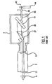
- FIG. 1 A sketch of such a prior art system is shown in FIG. 1 which is extracted from Japan Patent No. 2,696,285.
- the system shown includes output coupler (or front mirror) 4, laser chamber 3, chamber windows 11, and a grating based line narrowing unit 7.
- the line-narrowing unit 7 is typically provided on a lithography laser system as an easily replaceable unit and is sometimes called a "line narrowing package" or "LNP" for short.
- This prior art unit includes two beam expanding prisms 27 and 29 and a grating 16 disposed in a Litrow configuration. Gratings used in these systems are extremely sensitive optical devices.
- a typical grating surface may have 10,000 grooves per inch created in an aluminum layer or layers on a thick glass substrate.
- FIG. 2 is a sketch showing a prior art line narrowing unit fabricated by Applicants' employer, Cymer, Inc., as a part of a prior art line narrowed lithography KrF laser system incorporating such a device.
- the unit includes three beam expanding prisms 8, 10 and 12, a tuning mirror 14 and a grating 16. Note that the nitrogen purge from bottle 44 enters the unit on the back side of the tuning mirror 46 to avoid purge flow directly on the grating face.
- the wavelength of the laser beam 6 is controlled in a feedback arrangement in which the wavelength of the beam is measured by monitor 22 and computer controller 24 uses the wavelength information to adjust the angular position of tuning mirror 14 to control the wavelength to a desired value.
- the bandwidth control device 20 is used to mechanically bend grating 16 to make it slightly concave, for example. This device is described in detail in U.S. Patent No. 5,095,492 assigned to Cymer. Use of this device permits reduction of the bandwidth somewhat, but it still goes out of specification when the laser is run at high duty cycle.
- Line narrowed ultraviolet laser light sources currently in use in the integrated circuit industry typically produce about 10 mJ per pulse at repetition rates of about 1000 Hz and duty factors of about 20 percent. Increased integrated circuit production can be achieved at higher repetition rates and greater duty cycles.
- Applicants' employer is currently selling a 2000 Hz gas discharge lithography laser and Applicants and their fellow workers have designed a 4000 Hz gas discharge lithography laser. Applicants have experienced difficulties maintaining consistent narrow bandwidths at these higher repetition rates and duty cycles.
- a line narrowed laser having a grating base line narrowing device according to the preamble of claim 1 is known from US 6,212,217 B1.
- the present invention provides a grating based line narrowing device for line narrowing lasers producing high energy laser beams having the features set out in claims 1 and 8.
- a flexural grating mount is provided which virtually eliminates stress on the grating caused by differential thermal expansion between the grating and the LNP housing structure for minimizing adverse effects of heat produced by the laser beam inside the line narrowing device.
- the grating which in a preferred embodiment is comprised of a very thin lined aluminum surface on a thick ulna low expansion glass substrate is attached to an aluminum housing structure using a flexural grating mount.
- At least one flexure joint is provided in the grating mount which permits thermal expansion and contraction of the aluminum housing without producing undesirable mechanical stresses in the glass substrate of the grating.
- the mount comprises a metal plate and the flexure joint is a H-Flex joint which is machined into the metal plate.
- two H-Flex joints are provided in other embodiments, the flexure joint is a dovetail joint permitting one end of the mount to slip relative to the other.
- a stream of gas is directed across the face of the grating.
- the effect of a hot gas layer on the face of the grating is reduced with the use of helium as a purge gas and in other embodiments the purge gas pressure is reduced to reduce the optical effects of the hot gas layer.
- a prior art line narrowed KrF excimer laser operating at relatively low average power, typically less than 5W will produce a laser beam centered at about 248 nm with a bandwidth of less than 0.6 pm.
- the laser can run without problems at high rep rate, up to 2000 Hz and even above that as long as average power is below 5W.
- the laser is run in continuous mode which, at 2000 Hz and 10 mJ pulse energy, is equivalent to 20W average power.
- the bandwidth increases gradually over a period of about 5 to 20 minutes from initial bandwidth of less than 0.6 pm, and remains substantially higher than 0.6 pm.
- Such an increase in bandwidth should be avoided in microlithography production runs, because it will cause images to blur due to chromatic alterations of projection lenses.
- Another important application is when the laser is used to test thermal properties at high duty cycles of other lithography components, such as the projection lens itself. In this application, the laser is supposed to maintain its bandwidth and other parameters within the specification during the duration of the test.
- Lithography laser systems currently being tested for use in production include lasers designed to operate at 4000 Hz. Maintaining desired laser beam quality at these increased repetition rates is a challenge. Thermal effects are increased substantially as compared to the 2000 Hz systems.
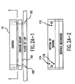
- FIG. 2A is a side view showing a prior art method of mounting grating 16 to the floor of the LNP enclosure.
- the thick glass substrate of the grating is attached to mounting plate 16A at each of three spots with very short epoxy pillars.
- FIG. 2B shows the approximate pillar horizontal positions at 17A, 17B and 17C.
- the mounting plate is screwed securely to the floor of the LNP enclosure with two screws 16B and 16C.
- the mounting plate is made of invar which has a co-efficient of thermal expansion close to zero and to that of the grating glass substrate which ultra low expansion glass and is also close to zero.
- the chamber enclosure is aluminum which has a co-efficient of thermal expansion substantially different from both invar and the grating glass substrate.
- FIGS. 11A and 11B are bottom views of a grating mount for minimizing thermal stress on the grating.
- This mount is comprised of two main parts 100 and 102. Part 102 slips into a dovetail slot 104 in part 100. Part 102 is bolted to the floor of the LNP with threaded hole 106 and part 100 is bolted to the floor of the LNP with threaded hole 104.
- FIG. 11C shows the dovetail slot in part 100 and FIG. 11D is an end view of part 102 showing how it is designed for a tight sliding fit in the slot.
- FIG. 11E shows part 102 positioned inside slot 104 in part 100.
- Two spring tensioned rollers 108 compress part 102 against side 110 of slot 104.
- the grating (not shown) is preferably mounted on top of part 100 using three short epoxy pillars about 1 cm in diameter and 4 mils high. This design permits the LNP floor to expand and contract without putting mechanical stress on the grating.
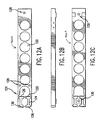
- FIGS. 12A; B and C are top, side and bottom views respectively of a grating mount with a single H-Flex joint.
- This mount is comprised of invar which, as stated above has a very small thermal co-efficient of expansion about the same as the fused silicon grating glass substrate.
- the mount is about 1/2 inch thick and has a length approximately equal to the thick glass substrate of the grating to be mounted on it. Holes 120 are cut into the mount primarily to reduce its weight.
- An H-Flex joint 121 is machined into the mount as shown in FIG. 12A.
- Two dogbone shaped holes 124 are cut into the mount producing an "H" shape flex joint so as to leave four flex legs 126 each about 0.060 inch (1,5 mm) thick.
- the grating is preferably mounted to the mount with three short epoxy pillars at locations 128 about 4 mils (25 ⁇ m) high and 1 cm in diameter as shown in FIG. 12A.
- the mount is screwed securely to the bottom of the LNP enclosure using threaded holes 130 shown in FIG. 12C.
- the H-Flex joint permits thermal expansion and contraction of the enclosure bottom without transmittal of any significant stress to the grating.
- the joint provides very little resistance to small forces in the long direction of the grating.
- the expansion co-efficient is about 0.001 inch per pound (56 ⁇ m/kg), in this long direction, but is extremely strong and resistant to forces in any other direction.
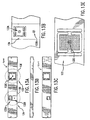
- FIG. 13A is a top view
- FIG. 13B is a side view
- FIG. 13C is a bottom view.
- This mount is similar to the one described above and shown in FIG. 12A. However, this mount has two H-Flex joints 134 and 133 as shown enlarged in FIGS. 13D and 13E respectively.
- the mount is made of aluminum as is the LNP enclosure.
- the mount is mounted to the enclosure as described in the previous embodiment.
- the grating is attached to the mount with three short epoxy pillars as described above at the positions 132A, 132B and 132C as shown in FIGS. 13A, 13D and 13E.
- the surface of the mount at the epoxy positions is preferably abraded with #40 grit dry blast alumina to produce a good epoxy surface.
- the legs of H-Flex 134 and H-Flex 133 are about 0.030 inch (0,76 mm) wide. Flex 133 permits expansion of the mount relative to the grating in the long direction of the grating and Flex 134 permits expansion in a short direction of the grating as indicated by the drawings.
- the second H-Flex joint permits the use of aluminum as the mount material which is less expensive and easier to machine than invar. Preferably, a four mill shim is used in this and the other embodiments when attaching the grating to the mount to assure that the epoxy pillar is the correct thickness (i.e., height).
- grating mounts should take into consideration the material used for the mount.
- invar is used for the mount which as a thermal co-efficient of thermal expansion similar to the thick ULE glass grating substrate. Therefore, the grating is attached with the three short epoxy pillars at two far apart locations to the long part of the mount with no attachment to the short part of the mount.
- one end of the long portion of the mount is attached to the chamber and the short portion of the mount at the other end of the mount is separately attached to the chamber.
- the flexure joint in both examples permit the mount and the chamber (having significantly different co-efficients of expansion) to expand and contract at different rates.
- the long portion of the mount is securely attached at two locations to the housing. This produces no significant stresses since both the mount and the housing are aluminum.
- the grating substrate which has a co-efficient of expansion substantially different from aluminum is attached to each of the three separate parts of the mount which by reason of the two flexure joints are free to move relative to each other.
- the mount were made of aluminum then in each case the long part of the mount only should be attached to the chamber floor and the grating should be attached to both parts.
- invar were used for the mount, the grating should be attached to the long solid part and the mount should be attached to the chamber at points 132A, 132B and 132C.
- This hot gas is heated by the grating surface, which in turn is heated by absorbing a portion of incident laser beam.
- a portion of incident laser beam Typically, as much as 15 to 20% of incident light might be absorbed by grating surface.
- the surface temperature of the grating might rise 10 to 15°C. This temperature increase is non-uniform, it is higher in the middle of the grating and lower at the ends as shown in FIG. 9. Therefore, the air in front of the middle portion of the grating is hotter than the air in front of the edges. Therefore, when the laser beam 80 incidents on the grating surface 86 it goes through this boundary layer 82. Because this air has the same pressure, the hotter the air, the less its density is.
- the air near the center of the grating is less dense, than the air near the edges. Because of that, the laser beam 80 will have different phase shifts when it goes to the middle portion of the grating and edges. So, the incoming beam with parallel wavefront 88 will have a curved wavefront 90, corresponding to divergent beam. This happens even if grating 16 is perfectly flat.
- FIGS. 4A and 4B A first preferred embodiment of the present invention is shown in FIGS. 4A and 4B.
- the nitrogen purge of about 2 liters per minute is flowed upward through approximately 1 mm diameter holes spaced at 1 ⁇ 4 inch 6,35 mm in a 10 inch 25,4 cm long 3/8 inch 9,5 mm ID tube functioning as a purge gas manifold.
- Barrier plate 60 and barrier cover 62 force most of the nitrogen purge flow in the direction shown by the arrows in FIG. 4B.
- This arrangement has produced excellent results as shown by the chart in FIG. 5.
- an increase in the output average power from 0.1 W to 20W resulted in variations within 0.4 to 0.5 pm. It is interesting to note that at 10W average power, the bandwidth is actually slightly smaller than at 0.1 W.
- this purge does not substantially reduce the temperature of the grating.
- the grating remains hot. What the purge does is to rather continuously displace air in front of the grating, so it does not have time to heat up by the grating. Very small flow rate and, correspondingly, gas velocity prevents any air distortions caused by the flow itself from affecting laser operation.
- the cavity between the grating and the barrier is not sealed and purge gas in permitted to circulate into and out of the cavity as shown at 64 and 66.
- the tubes 68 leading to and from fan 70 connect near the center of slitted tubes 72 and 74 which is just above and below the hottest area on grating 16.
- a second solution to the hot gas layers problem is to reduce the gas pressure in the line narrowing package.
- Gas convection modulates the gas density spatially, causing an inhomogeneous distribution of the refractive index, which in turn leads to phase front aberration.
- the magnitude of any aberration caused by gas density fluctuations, which are due to the gas convection close to the heated grating surface, is approximately linearly dependant on the nominal value of the susceptibility or the refractive index and thus the gas density.
- Convective cooling of the surface of the grating and other optical components is not substantially reduced so long as the mean free path of the gas molecules is not less than distances between the "hot" and "cold” surfaces in the LNP. If we assume these distances are about 10 cm then as a rule of thumb we would say that the gas pressure should not be reduced beyond the pressure where the mean free path length is about 10 cm. That pressure is in the range of about 1 to 10 millibar so that the density of the gas in the LNP is about 0.1 to 1.0 percent the density at atmospheric conditions.
- FIG. 10 is a sketch showing a system for maintaining a controlled pressure in the LNP at about 1 to 10 millibar.
- the nitrogen enters sealed LNP 7 through orifice 90.
- Vacuum pump 92 is used to create the vacuum in the LNP and the desired vacuum is maintained by controller 94 using a feedback signal from pressure sensor 96 to control needle valve 98. Since LNP is a sealed system and the pressure is approximately at equilibrium, sensor 96 may be thermocoupled.
- Helium has a smaller differential refractive index so that a hot layer will cause less distortion.
- helium has much better heat transfer properties than nitrogen.
- Argon may also be used with the same advantages. Helium; however, is much more expensive than nitrogen.
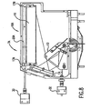
- FIG. 7 is a combination block diagram schematic drawing of the entire laser system and FIG. 8 is a drawing of the LNP according to an embodiment with the added feedback control features.
- the curvature of the grating is controlled by grating curvature stepper motor 30 to compensate for the distortion caused by the hot gas layer on the face of the grating. Therefore, the scope of the present invention should be determined by the appended claims.
Landscapes
- Physics & Mathematics (AREA)
- Electromagnetism (AREA)
- Optics & Photonics (AREA)
- Engineering & Computer Science (AREA)
- Plasma & Fusion (AREA)
- General Physics & Mathematics (AREA)
- Lasers (AREA)
- Cleaning In General (AREA)
Abstract
Description
- This invention relates to lasers and in particular to high power gas discharge lasers with a grating based line-narrowing unit.
- Gas discharge ultraviolet lasers used as light sources for integrated circuit lithography typically are line narrowed. A preferred prior art line narrowing technique is to use a grating based line-narrowing unit along with an output coupler to form the laser resonance cavity. The gain medium within this cavity is produced by electrical discharges into a circulating laser gas such as krypton, fluorine and neon (for a KrF laser); argon, fluorine and neon (for an ArF laser); or fluorine and helium and/or neon (for an F2 laser).
- A sketch of such a prior art system is shown in FIG. 1 which is extracted from Japan Patent No. 2,696,285. The system shown includes output coupler (or front mirror) 4,
laser chamber 3,chamber windows 11, and a grating basedline narrowing unit 7. The line-narrowing unit 7 is typically provided on a lithography laser system as an easily replaceable unit and is sometimes called a "line narrowing package" or "LNP" for short. This prior art unit includes twobeam expanding prisms grating 16 disposed in a Litrow configuration. Gratings used in these systems are extremely sensitive optical devices. A typical grating surface may have 10,000 grooves per inch created in an aluminum layer or layers on a thick glass substrate. These gratings and techniques for fabricating them are described in U.S. Patent No. 5,999,318 which is incorporated herein by reference. A prior art technique for avoiding distortion of the grating surface is to mount the grating on a metal grating mount made of a material having a small co-efficient of thermal expansion closely matched to the thermal expansion co-efficient of the grating glass substrate. The gratings deteriorate rapidly under ultraviolet radiation in the presence of oxygen in standard air. For this reason, the optical components of line narrowing units for lithography lasers are typically purged continuously during operation with nitrogen. - FIG. 2 is a sketch showing a prior art line narrowing unit fabricated by Applicants' employer, Cymer, Inc., as a part of a prior art line narrowed lithography KrF laser system incorporating such a device. The unit includes three
beam expanding prisms 8, 10 and 12, atuning mirror 14 and agrating 16. Note that the nitrogen purge frombottle 44 enters the unit on the back side of thetuning mirror 46 to avoid purge flow directly on the grating face. In this system the wavelength of thelaser beam 6 is controlled in a feedback arrangement in which the wavelength of the beam is measured bymonitor 22 andcomputer controller 24 uses the wavelength information to adjust the angular position oftuning mirror 14 to control the wavelength to a desired value. Thebandwidth control device 20 is used to mechanically bend grating 16 to make it slightly concave, for example. This device is described in detail in U.S. Patent No. 5,095,492 assigned to Cymer. Use of this device permits reduction of the bandwidth somewhat, but it still goes out of specification when the laser is run at high duty cycle. - For many years, designers for line narrowed lasers have believed that distortions of the laser beam could be caused by gas flow near the face of the grating. Therefore, laser designers in the past have made special efforts to keep the purge nitrogen from flowing directly on the face of the grating. Several examples of these efforts are described in the Japan Patent 2,696,285 referred to above. In the example shown in extracted FIG. 1, the purge flow is directed from N2 gas bottle 44 toward the back side of
grating 16 throughport 46. - Line narrowed ultraviolet laser light sources currently in use in the integrated circuit industry typically produce about 10 mJ per pulse at repetition rates of about 1000 Hz and duty factors of about 20 percent. Increased integrated circuit production can be achieved at higher repetition rates and greater duty cycles. Applicants' employer is currently selling a 2000 Hz gas discharge lithography laser and Applicants and their fellow workers have designed a 4000 Hz gas discharge lithography laser. Applicants have experienced difficulties maintaining consistent narrow bandwidths at these higher repetition rates and duty cycles.
- A need exists for reliable line narrowing devices and techniques for high repetition rate, high duty cycle gas discharge lasers.
- A line narrowed laser having a grating base line narrowing device according to the preamble of
claim 1 is known from US 6,212,217 B1. - The present invention provides a grating based line narrowing device for line narrowing lasers producing high energy laser beams having the features set out in
claims 1 and 8. - A flexural grating mount is provided which virtually eliminates stress on the grating caused by differential thermal expansion between the grating and the LNP housing structure for minimizing adverse effects of heat produced by the laser beam inside the line narrowing device. According to the invention the grating which in a preferred embodiment is comprised of a very thin lined aluminum surface on a thick ulna low expansion glass substrate is attached to an aluminum housing structure using a flexural grating mount. At least one flexure joint is provided in the grating mount which permits thermal expansion and contraction of the aluminum housing without producing undesirable mechanical stresses in the glass substrate of the grating. In some embodiments the mount comprises a metal plate and the flexure joint is a H-Flex joint which is machined into the metal plate. In another embodiment, two H-Flex joints are provided In other embodiments, the flexure joint is a dovetail joint permitting one end of the mount to slip relative to the other. In another preferred embodiments a stream of gas is directed across the face of the grating. In other embodiments the effect of a hot gas layer on the face of the grating is reduced with the use of helium as a purge gas and in other embodiments the purge gas pressure is reduced to reduce the optical effects of the hot gas layer.
-
- FIG. 1 shows a first prior art line narrowed laser system.
- FIG. 2 shows a second prior art line narrowed laser system.
- FIGS. 2A and 2B show a prior art grating mounting technique.
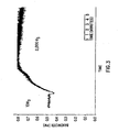
- FIG. 3 shows adverse effects on bandwidth of a hot gas layer on the face of a line narrowing grating.
- FIG. 4A and 4B show a preferred embodiment of the present invention.
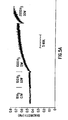
- FIG. 5A shows bandwidth traces at various rep rates with prior art purging.
- FIG. 5B shows bandwidth traces at various rep rates with purging in accordance with the present invention.
- FIGS. 6A, 6B and 6C show alternate embodiments of the present invention.
- FIGS. 7 and 8 show a LNP equipped for fast feedback control.
- FIG. 9 shows the heating of the gas layer on the grating surface.
- FIG. 10 shows a technique for reducing the purge gas pressure.
- FIGS. 11A, B, C, and D show features of a preferred embodiment of the present invention.
- FIGS. 12A, B and C show features of another preferred embodiment of the present invention.
- FIGS. 13A, B, C, D, and E show features of another preferred embodiment of the present invention.
- Preferred embodiments of the present invention can be described by reference to the figures.
- A prior art line narrowed KrF excimer laser operating at relatively low average power, typically less than 5W will produce a laser beam centered at about 248 nm with a bandwidth of less than 0.6 pm. The laser can run without problems at high rep rate, up to 2000 Hz and even above that as long as average power is below 5W. A typical lithography KrF excimer laser has a pulse energy of 10 mJ. Therefore, in order to avoid increases in average power, the laser has to be operated with a relatively low duty cycle. For example, it can be run at 2 kHz in bursts of 200 pulses with pause between bursts of about 0.45 second. Such an operation will produce an average power of :

- Problems with bandwidth control start to appear when the average power is increased. This happens, for example, when the interburst delay is decreased. For example, laser running the same 200 pulse bursts with 0.1 second interburst delay will have an average power of :

- At maximum, the laser is run in continuous mode which, at 2000 Hz and 10 mJ pulse energy, is equivalent to 20W average power.
- When the prior art laser system is run with high average power, the bandwidth increases gradually over a period of about 5 to 20 minutes from initial bandwidth of less than 0.6 pm, and remains substantially higher than 0.6 pm. Such an increase in bandwidth should be avoided in microlithography production runs, because it will cause images to blur due to chromatic alterations of projection lenses. Another important application is when the laser is used to test thermal properties at high duty cycles of other lithography components, such as the projection lens itself. In this application, the laser is supposed to maintain its bandwidth and other parameters within the specification during the duration of the test.
- Lithography laser systems currently being tested for use in production include lasers designed to operate at 4000 Hz. Maintaining desired laser beam quality at these increased repetition rates is a challenge. Thermal effects are increased substantially as compared to the 2000 Hz systems.
- FIG. 2A is a side view showing a prior art method of mounting grating 16 to the floor of the LNP enclosure. In this case, the thick glass substrate of the grating is attached to mounting
plate 16A at each of three spots with very short epoxy pillars. FIG. 2B shows the approximate pillar horizontal positions at 17A, 17B and 17C. The mounting plate is screwed securely to the floor of the LNP enclosure with twoscrews - When Applicants first began seeing beam quality deterioration with increasing beam energy, the cause was not apparent and many potential causes were investigated surface heating of the purge gas on the face of the grating was one cause and it was largely corrected by directing a flow of purge gas directly on the grating face as described in a following section. However, this did not completely eliminate the problem.
- Finally, one of the Applicants loosened
screw 16C as shown in FIG. 2A and the beam quality improved substantially. Applicants then recognized that differential thermal expansion was causing an undesirable bending of the grating which was causing the deterioration in beam quality. As a result, Applicants have designed several modifications in the LNP to solve this problem. - One solution to the problem is shown in FIGS. 11A, B, C, D and E. FIGS. 11A and 11B are bottom views of a grating mount for minimizing thermal stress on the grating. This mount is comprised of two
main parts Part 102 slips into adovetail slot 104 inpart 100.Part 102 is bolted to the floor of the LNP with threadedhole 106 andpart 100 is bolted to the floor of the LNP with threadedhole 104. FIG. 11C shows the dovetail slot inpart 100 and FIG. 11D is an end view ofpart 102 showing how it is designed for a tight sliding fit in the slot. FIG. 11E showspart 102 positioned insideslot 104 inpart 100. Two spring tensionedrollers 108compress part 102 againstside 110 ofslot 104. The grating (not shown) is preferably mounted on top ofpart 100 using three short epoxy pillars about 1 cm in diameter and 4 mils high. This design permits the LNP floor to expand and contract without putting mechanical stress on the grating. - A second embodiment of the present invention can be described by reference to FIGS. 12A; B and C which are top, side and bottom views respectively of a grating mount with a single H-Flex joint. This mount is comprised of invar which, as stated above has a very small thermal co-efficient of expansion about the same as the fused silicon grating glass substrate. The mount is about 1/2 inch thick and has a length approximately equal to the thick glass substrate of the grating to be mounted on it.
Holes 120 are cut into the mount primarily to reduce its weight. An H-Flex joint 121 is machined into the mount as shown in FIG. 12A. Two dogbone shapedholes 124 are cut into the mount producing an "H" shape flex joint so as to leave fourflex legs 126 each about 0.060 inch (1,5 mm) thick. The grating is preferably mounted to the mount with three short epoxy pillars atlocations 128 about 4 mils (25 µm) high and 1 cm in diameter as shown in FIG. 12A. - The mount is screwed securely to the bottom of the LNP enclosure using threaded
holes 130 shown in FIG. 12C. The H-Flex joint permits thermal expansion and contraction of the enclosure bottom without transmittal of any significant stress to the grating. The joint provides very little resistance to small forces in the long direction of the grating. The expansion co-efficient is about 0.001 inch per pound (56 µm/kg), in this long direction, but is extremely strong and resistant to forces in any other direction. - A third embodiment can be described by reference to FIGS. 13A, B, C, D, E and F. FIG 13A is a top view, FIG. 13B is a side view and FIG. 13C is a bottom view. This mount is similar to the one described above and shown in FIG. 12A. However, this mount has two H-
Flex joints positions Flex 134 and H-Flex 133 are about 0.030 inch (0,76 mm) wide.Flex 133 permits expansion of the mount relative to the grating in the long direction of the grating andFlex 134 permits expansion in a short direction of the grating as indicated by the drawings. The second H-Flex joint permits the use of aluminum as the mount material which is less expensive and easier to machine than invar. Preferably, a four mill shim is used in this and the other embodiments when attaching the grating to the mount to assure that the epoxy pillar is the correct thickness (i.e., height). - The reader should note that preferred designs of grating mounts should take into consideration the material used for the mount. For example, in the FIGS. 11A-D and in FIGS. 12A-C examples, invar is used for the mount which as a thermal co-efficient of thermal expansion similar to the thick ULE glass grating substrate. Therefore, the grating is attached with the three short epoxy pillars at two far apart locations to the long part of the mount with no attachment to the short part of the mount. In these two examples, one end of the long portion of the mount is attached to the chamber and the short portion of the mount at the other end of the mount is separately attached to the chamber. The flexure joint in both examples permit the mount and the chamber (having significantly different co-efficients of expansion) to expand and contract at different rates.
- In the FIG. 13A-E examples, the long portion of the mount is securely attached at two locations to the housing. This produces no significant stresses since both the mount and the housing are aluminum. The grating substrate which has a co-efficient of expansion substantially different from aluminum is attached to each of the three separate parts of the mount which by reason of the two flexure joints are free to move relative to each other. Thus, if in the FIGS. 11A-D and FIGS. 12A-C examples the mount were made of aluminum then in each case the long part of the mount only should be attached to the chamber floor and the grating should be attached to both parts. Also if in FIGS. 13A-E example, invar were used for the mount, the grating should be attached to the long solid part and the mount should be attached to the chamber at
points - Applicants have determined that the poor performance at higher repetition rates as shown in FIG. 3 is partly the result of the development of a hot layer of nitrogen which builds up over a period of about 5 minutes on the face of the grating 48.
- This hot gas is heated by the grating surface, which in turn is heated by absorbing a portion of incident laser beam. Typically, as much as 15 to 20% of incident light might be absorbed by grating surface. The surface temperature of the grating might rise 10 to 15°C. This temperature increase is non-uniform, it is higher in the middle of the grating and lower at the ends as shown in FIG. 9. Therefore, the air in front of the middle portion of the grating is hotter than the air in front of the edges. Therefore, when the
laser beam 80 incidents on thegrating surface 86 it goes through thisboundary layer 82. Because this air has the same pressure, the hotter the air, the less its density is. So, the air near the center of the grating is less dense, than the air near the edges. Because of that, thelaser beam 80 will have different phase shifts when it goes to the middle portion of the grating and edges. So, the incoming beam withparallel wavefront 88 will have acurved wavefront 90, corresponding to divergent beam. This happens even if grating 16 is perfectly flat. - Applicants have developed preferred modifications to the line narrowing unit to substantially eliminate this hot nitrogen layer.
- A first preferred embodiment of the present invention is shown in FIGS. 4A and 4B. In this case the nitrogen purge of about 2 liters per minute is flowed upward through approximately 1 mm diameter holes spaced at ¼
inch 6,35 mm in a 10inch 25,4 cm long 3/8inch 9,5 mm ID tube functioning as a purge gas manifold.Barrier plate 60 and barrier cover 62 force most of the nitrogen purge flow in the direction shown by the arrows in FIG. 4B. This arrangement has produced excellent results as shown by the chart in FIG. 5. In this case, an increase in the output average power from 0.1 W to 20W resulted in variations within 0.4 to 0.5 pm. It is interesting to note that at 10W average power, the bandwidth is actually slightly smaller than at 0.1 W. - It is important that the purge flow across the face of the grating be carefully controlled to avoid flow related distortions. Applicants have tested various flow rates and have determined that excessive flow can do more harm than good. For example, a flow rate of 20 liters per minute produced very poor results. Recommended flow rates are in the range of about 0.5 liters per minute to about 10 liters per minute.
- It is also important to note, that this purge does not substantially reduce the temperature of the grating. The grating remains hot. What the purge does is to rather continuously displace air in front of the grating, so it does not have time to heat up by the grating. Very small flow rate and, correspondingly, gas velocity prevents any air distortions caused by the flow itself from affecting laser operation.
- There are many potential arrangements to provide gas flow across the face of the grating to prevent the buildup of the thermal layer which causes the problem shown in FIG. 3. For example, a narrow slit of about 0.5 mm running the length of the manifold could be used instead of the small holes. Also smoother flow could be provided with a slit type nozzle such as shown in cross section in FIG. 6A or slit nozzles could be provided both at the top and bottom of the grating as shown in FIG. 6B. Also, flow across the grating face could be provided with a very small fan in a semi-closed system as shown in FIG. 6C. In this case, the regular nitrogen purge could be provided as in the prior art as shown in FIG. 2. In the FIG. 6C embodiment, the cavity between the grating and the barrier is not sealed and purge gas in permitted to circulate into and out of the cavity as shown at 64 and 66. The
tubes 68 leading to and fromfan 70 connect near the center ofslitted tubes - A second solution to the hot gas layers problem is to reduce the gas pressure in the line narrowing package.
- Gas convection modulates the gas density spatially, causing an inhomogeneous distribution of the refractive index, which in turn leads to phase front aberration. The magnitude of any aberration caused by gas density fluctuations, which are due to the gas convection close to the heated grating surface, is approximately linearly dependant on the nominal value of the susceptibility or the refractive index and thus the gas density.
- Convective cooling of the surface of the grating and other optical components is not substantially reduced so long as the mean free path of the gas molecules is not less than distances between the "hot" and "cold" surfaces in the LNP. If we assume these distances are about 10 cm then as a rule of thumb we would say that the gas pressure should not be reduced beyond the pressure where the mean free path length is about 10 cm. That pressure is in the range of about 1 to 10 millibar so that the density of the gas in the LNP is about 0.1 to 1.0 percent the density at atmospheric conditions.
- FIG. 10 is a sketch showing a system for maintaining a controlled pressure in the LNP at about 1 to 10 millibar. The nitrogen enters sealed
LNP 7 throughorifice 90.Vacuum pump 92 is used to create the vacuum in the LNP and the desired vacuum is maintained bycontroller 94 using a feedback signal frompressure sensor 96 to controlneedle valve 98. Since LNP is a sealed system and the pressure is approximately at equilibrium,sensor 96 may be thermocoupled. - Another solution to reduce the hot layer effect is to purge the LNP with helium. Helium has a smaller differential refractive index so that a hot layer will cause less distortion. In addition, helium has much better heat transfer properties than nitrogen. Argon may also be used with the same advantages. Helium; however, is much more expensive than nitrogen.
- Persons skilled in the art will recognize that in addition to the above-described specific embodiments of the present invention, there are many other embodiments lying within the scope of the invention as defined in the claims. For example, materials other than invar or aluminum can be used for the mount, but for reasons explained above the material should have a co-efficient of thermal expansion matching either the rigid grating substrate or the chamber housing. Another technique for dealing with the hot gas layer is to provide active bandwidth control to correct for the adverse effects of the hot gas layer. Techniques for substantially real time control of several wavelength parameters are described in a United States patent application filed September 3, 1999, Serial No. 09/390,579 . These techniques include fast feedback control of the position of the beam expanding prisms, grating curvature and tuning mirror position. Control of the position of the laser chamber is also provided. FIG. 7 is a combination block diagram schematic drawing of the entire laser system and FIG. 8 is a drawing of the LNP according to an embodiment with the added feedback control features. In this embodiment, the curvature of the grating is controlled by grating
curvature stepper motor 30 to compensate for the distortion caused by the hot gas layer on the face of the grating. Therefore, the scope of the present invention should be determined by the appended claims.
Claims (17)
- A grating based line narrowing device for line narrowing a laser producing high energy laser beams, said device comprising:(A) a grating (16) having a grooved surface layer or layers fixed on a rigid grating substrate, said grating defining a long direction perpendicular to the grating grooves parallel to the plane of the grating,(B) a chamber (7) for housing at least said grating,(C) a beam expanding means (8, 10, 12) for expanding a beam (6) from said laser to produce an expanded beam,(D) a tuning means (14) for directing said expanded beam onto the grating face in order to select from said expanded beam a desired range of wavelengths,
characterized by(E) a purge means (90) for providing a purge gas for purging said chamber (7), and(F) a flexural grating mount (100, 102, 1200, 1201, 1300, 1301) comprising:(1) a first part (100, 1200, 1300) and a second part (102, 1201, 1301) said first part and said second part each being securely attached to said chamber, and said grating being securely attached to said first part only;b) a flexure joint connecting said first part to said second part so as to permit said second part to move relatively easily in said long direction relative to said first part. - A device as in Claim 1 wherein said flexure joint is an H-Flex joint (121).
- A device as in Claim 1 wherein said flexure joint is a dovetail sliding joint (100, 102).
- A device as in Claim 1 wherein said mount is comprised of a material having a co-efficient of thermal expansion closely matched to said rigid grating substrate.
- A device as in Claim 1 wherein said heat removal means comprises a purge gas manifold having a plurality of small ports for directing purge gas across the grating face.
- A device as in Claim 2 wherein said heat removal means comprises a grating purge gas flow control means (98, 94) for controlling purge gas flow across the grating face.
- A device as in Claim 3 wherein said purge gas flow control means comprises structures defining a flow path across said grating face and then away from said grating face.
- A grating based line narrowing device for line narrowing a laser producing high energy laser beams, said device comprising:(A) a grating (16) having a grooved surface layer or layers fixed on a rigid grating substrate, said grating defining a long direction perpendicular to the grating grooves parallel to the plane of the grating,(B) a chamber (7) for housing at least said grating,(C) a beam expanding means (8, 10, 12) for expanding a beam (6) from said laser to produce an expanded beam,(D) a tuning means (14) for directing said expanded beam onto the grating face in order to select from said expanded beam a desired range of wavelengths,
characterized by(E) a purge means (90) for providing a purge gas for purging said chamber, and(F) a flexural grating mount (100, 102, 1200, 1201, 1300, 1301) comprising:a) a first part (100,1200,1300) and a second part (102, 1201, 1301), said first part and said second part each being securely attached to said rigid grating substrate, and said chamber being securely attached to said first part only;b) a flexure joint connecting said first part to said second part so as to permit said second part to move relatively easily in said long direction relative to said first part. - A device as in Claim 8 wherein said flexure joint is an H-Flex joint (121).
- A device as in Claim 8 wherein said flexure joint is a dovetail sliding joint (100, 102).
- A device as in Claim 8 wherein said mount is comprised of a material having a co-efficient of thermal expansion closely matched to said rigid grating substrate.
- A device as in Claim 8 and further comprising a heat removal means for removing heat from a hot purge gas layer adjacent to said grooved surface layer.
- A device as in Claim 12 wherein said heat removal means comprises a purge gas manifold having a plurality of small ports for directing purge gas across the grating face.
- A device as in Claim 12 wherein said heat removal means comprises a grating purge gas flow control means (98, 94) for controlling purge gas flow across the grating face.
- A device as in Claim 14 wherein said purge gas flow control means comprises structures defining a flow path across said grating face and then away from said grating face.
- A device as in Claim 1 wherein said mount further comprises a second flexure joint (133, 134).
- A device as in Claim 8 wherein said mount further comprises a second flexure joint (133, 134).
Applications Claiming Priority (3)
| Application Number | Priority Date | Filing Date | Title |
|---|---|---|---|
| US895664 | 1978-04-12 | ||
| US09/895,664 US6496528B2 (en) | 1999-09-03 | 2001-06-29 | Line narrowing unit with flexural grating mount |
| PCT/US2002/017999 WO2003003531A1 (en) | 2001-06-29 | 2002-06-05 | Line narrowing unit with flexural grating mount |
Publications (3)
| Publication Number | Publication Date |
|---|---|
| EP1407521A1 EP1407521A1 (en) | 2004-04-14 |
| EP1407521A4 EP1407521A4 (en) | 2005-11-23 |
| EP1407521B1 true EP1407521B1 (en) | 2007-05-16 |
Family
ID=25404857
Family Applications (1)
| Application Number | Title | Priority Date | Filing Date |
|---|---|---|---|
| EP02744246A Expired - Lifetime EP1407521B1 (en) | 2001-06-29 | 2002-06-05 | Line narrowing unit with flexural grating mount |
Country Status (7)
| Country | Link |
|---|---|
| US (1) | US6496528B2 (en) |
| EP (1) | EP1407521B1 (en) |
| JP (1) | JP4025289B2 (en) |
| KR (1) | KR100913349B1 (en) |
| CN (1) | CN100416950C (en) |
| DE (1) | DE60220166T2 (en) |
| WO (1) | WO2003003531A1 (en) |
Cited By (1)
| Publication number | Priority date | Publication date | Assignee | Title |
|---|---|---|---|---|
| DE102009035789A1 (en) | 2009-07-31 | 2010-11-25 | Carl Zeiss Laser Optics Gmbh | Optical system useful in a device for laser material processing, comprises a housing, optical elements arranged inside the housing and having an optically active surface, a reception zone for receiving a flushing gas, and a flushing device |
Families Citing this family (24)
| Publication number | Priority date | Publication date | Assignee | Title |
|---|---|---|---|---|
| US6792023B1 (en) | 1998-06-04 | 2004-09-14 | Lambda Physik Ag | Method and apparatus for reduction of spectral fluctuations |
| CA2390123A1 (en) * | 1999-11-30 | 2001-06-07 | Richard L. Sandstrom | High power gas discharge laser with helium purged line narrowing unit |
| US6834069B1 (en) * | 1999-12-15 | 2004-12-21 | Lambda Physik Ag | Molecular fluorine laser with intracavity polarization enhancer |
| US7346093B2 (en) * | 2000-11-17 | 2008-03-18 | Cymer, Inc. | DUV light source optical element improvements |
| US7088758B2 (en) | 2001-07-27 | 2006-08-08 | Cymer, Inc. | Relax gas discharge laser lithography light source |
| US7105836B2 (en) * | 2002-10-18 | 2006-09-12 | Asml Holding N.V. | Method and apparatus for cooling a reticle during lithographic exposure |
| US7180590B2 (en) | 2003-07-09 | 2007-02-20 | Ibsen Photonics A/S | Transmission spectrometer with improved spectral and temperature characteristics |
| JP2005191503A (en) * | 2003-12-26 | 2005-07-14 | Canon Inc | Laser apparatus, exposure method and apparatus |
| US7643522B2 (en) * | 2004-11-30 | 2010-01-05 | Cymer, Inc. | Method and apparatus for gas discharge laser bandwidth and center wavelength control |
| US20060114956A1 (en) * | 2004-11-30 | 2006-06-01 | Sandstrom Richard L | High power high pulse repetition rate gas discharge laser system bandwidth management |
| US7366219B2 (en) * | 2004-11-30 | 2008-04-29 | Cymer, Inc. | Line narrowing module |
| US7653095B2 (en) * | 2005-06-30 | 2010-01-26 | Cymer, Inc. | Active bandwidth control for a laser |
| US8379687B2 (en) | 2005-06-30 | 2013-02-19 | Cymer, Inc. | Gas discharge laser line narrowing module |
| US7321607B2 (en) * | 2005-11-01 | 2008-01-22 | Cymer, Inc. | External optics and chamber support system |
| US8259764B2 (en) | 2006-06-21 | 2012-09-04 | Cymer, Inc. | Bandwidth control device |
| US9018561B2 (en) | 2007-05-23 | 2015-04-28 | Cymer, Llc | High power seed/amplifier laser system with beam shaping intermediate the seed and amplifier |
| CN101755188A (en) * | 2007-07-18 | 2010-06-23 | 株式会社尼康 | Measuring method, stage device, and exposure device |
| US8014432B2 (en) * | 2009-03-27 | 2011-09-06 | Cymer, Inc. | Regenerative ring resonator |
| USRE45957E1 (en) | 2009-03-27 | 2016-03-29 | Cymer, Llc | Regenerative ring resonator |
| US8837536B2 (en) * | 2010-04-07 | 2014-09-16 | Cymer, Llc | Method and apparatus for controlling light bandwidth |
| DE102018209602B4 (en) | 2018-06-14 | 2022-05-12 | Carl Zeiss Smt Gmbh | Optical assembly for reducing a spectral bandwidth of an output beam of a laser |
| JP7203944B2 (en) * | 2019-02-20 | 2023-01-13 | ギガフォトン株式会社 | Gas laser device, method for emitting laser light from gas laser device, and method for manufacturing electronic device |
| KR102120709B1 (en) | 2019-07-22 | 2020-06-10 | 임채현 | Protecting bag |
| CN113681354B (en) * | 2021-08-20 | 2022-05-20 | 北京工研精机股份有限公司 | Feedback element mounting structure and ultra-precise hydrostatic guide rail applying same |
Family Cites Families (15)
| Publication number | Priority date | Publication date | Assignee | Title |
|---|---|---|---|---|
| US3208344A (en) * | 1961-01-09 | 1965-09-28 | Coleman Instr Corp | Mounting for deformable optical elements |
| US3503685A (en) * | 1967-03-15 | 1970-03-31 | Walter G Driscoll | Temperature compensated spectroscopic apparatus |
| US3845409A (en) | 1973-11-27 | 1974-10-29 | Us Air Force | Laser grating couplers |
| US4426131A (en) * | 1982-01-13 | 1984-01-17 | The United States Of America As Represented By The Secretary Of The Air Force | Replaceable diffraction gratings for cooled laser optics |
| DE3211868A1 (en) * | 1982-03-31 | 1983-05-26 | Fa. Carl Zeiss, 7920 Heidenheim | CHASSIS FOR OPTICAL DEVICES |
| DE3889323T2 (en) | 1987-09-26 | 1994-09-29 | Mitsubishi Electric Corp | LASER ARRANGEMENT. |
| US5095492A (en) | 1990-07-17 | 1992-03-10 | Cymer Laser Technologies | Spectral narrowing technique |
| JPH04314374A (en) | 1991-04-12 | 1992-11-05 | Komatsu Ltd | Narrow band laser device |
| JP2696285B2 (en) | 1991-12-16 | 1998-01-14 | 株式会社小松製作所 | Narrow band oscillation excimer laser device and purging method thereof |
| US6212217B1 (en) | 1997-07-01 | 2001-04-03 | Cymer, Inc. | Smart laser with automated beam quality control |
| US6192064B1 (en) * | 1997-07-01 | 2001-02-20 | Cymer, Inc. | Narrow band laser with fine wavelength control |
| US6147341A (en) * | 1998-02-13 | 2000-11-14 | Lucent Technologies Inc. | Temperature compensating device for fiber gratings |
| JP2000150998A (en) * | 1998-11-06 | 2000-05-30 | Komatsu Ltd | Narrowband module for excimer laser equipment |
| US6295399B1 (en) * | 1999-05-25 | 2001-09-25 | Lucent Technologies Inc. | Non-linear temperature compensating device for fiber gratings and a package therefor |
| US6735236B2 (en) * | 1999-09-03 | 2004-05-11 | Cymer, Inc. | High power gas discharge laser with line narrowing unit |
-
2001
- 2001-06-29 US US09/895,664 patent/US6496528B2/en not_active Expired - Lifetime
-
2002
- 2002-06-05 WO PCT/US2002/017999 patent/WO2003003531A1/en not_active Ceased
- 2002-06-05 EP EP02744246A patent/EP1407521B1/en not_active Expired - Lifetime
- 2002-06-05 KR KR1020037016873A patent/KR100913349B1/en not_active Expired - Lifetime
- 2002-06-05 CN CNB028130189A patent/CN100416950C/en not_active Expired - Lifetime
- 2002-06-05 JP JP2003509594A patent/JP4025289B2/en not_active Expired - Lifetime
- 2002-06-05 DE DE60220166T patent/DE60220166T2/en not_active Expired - Fee Related
Non-Patent Citations (1)
| Title |
|---|
| None * |
Cited By (1)
| Publication number | Priority date | Publication date | Assignee | Title |
|---|---|---|---|---|
| DE102009035789A1 (en) | 2009-07-31 | 2010-11-25 | Carl Zeiss Laser Optics Gmbh | Optical system useful in a device for laser material processing, comprises a housing, optical elements arranged inside the housing and having an optically active surface, a reception zone for receiving a flushing gas, and a flushing device |
Also Published As
| Publication number | Publication date |
|---|---|
| US20020034208A1 (en) | 2002-03-21 |
| CN100416950C (en) | 2008-09-03 |
| JP4025289B2 (en) | 2007-12-19 |
| WO2003003531A1 (en) | 2003-01-09 |
| DE60220166D1 (en) | 2007-06-28 |
| KR100913349B1 (en) | 2009-08-20 |
| KR20040020938A (en) | 2004-03-09 |
| EP1407521A4 (en) | 2005-11-23 |
| DE60220166T2 (en) | 2007-08-30 |
| EP1407521A1 (en) | 2004-04-14 |
| CN1522484A (en) | 2004-08-18 |
| JP2004531908A (en) | 2004-10-14 |
| US6496528B2 (en) | 2002-12-17 |
Similar Documents
| Publication | Publication Date | Title |
|---|---|---|
| US6496528B2 (en) | Line narrowing unit with flexural grating mount | |
| US6735236B2 (en) | High power gas discharge laser with line narrowing unit | |
| KR100909018B1 (en) | Laser lithography beam emission light source | |
| KR20010110699A (en) | Tunable laser with stabilized grating | |
| US20020141471A1 (en) | Resonator arrangement for bandwidth control | |
| US7277466B2 (en) | High power gas discharge laser with helium purged line narrowing unit | |
| WO2002093702A1 (en) | Gas discharge laser with improved beam path | |
| KR20070084624A (en) | Line Narrowing Module | |
| US6778584B1 (en) | High power gas discharge laser with helium purged line narrowing unit | |
| US7346093B2 (en) | DUV light source optical element improvements | |
| WO2000074183A1 (en) | Ultraviolet laser device | |
| US7352791B2 (en) | Optical systems including wavefront correcting optical surfaces | |
| US7283575B2 (en) | Narrow band electric discharge gas laser having improved beam direction stability | |
| TW563278B (en) | Line narrowing unit with flexural grating mount |
Legal Events
| Date | Code | Title | Description |
|---|---|---|---|
| PUAI | Public reference made under article 153(3) epc to a published international application that has entered the european phase |
Free format text: ORIGINAL CODE: 0009012 |
|
| 17P | Request for examination filed |
Effective date: 20031219 |
|
| AK | Designated contracting states |
Kind code of ref document: A1 Designated state(s): AT BE CH CY DE DK ES FI FR GB GR IE IT LI LU MC NL PT SE TR |
|
| AX | Request for extension of the european patent |
Extension state: AL LT LV MK RO SI |
|
| A4 | Supplementary search report drawn up and despatched |
Effective date: 20051011 |
|
| RIC1 | Information provided on ipc code assigned before grant |
Ipc: 7H 01S 3/08 A Ipc: 7H 01S 3/10 B Ipc: 7H 01S 3/1055 B |
|
| GRAP | Despatch of communication of intention to grant a patent |
Free format text: ORIGINAL CODE: EPIDOSNIGR1 |
|
| RBV | Designated contracting states (corrected) |
Designated state(s): DE FR GB NL |
|
| GRAS | Grant fee paid |
Free format text: ORIGINAL CODE: EPIDOSNIGR3 |
|
| GRAA | (expected) grant |
Free format text: ORIGINAL CODE: 0009210 |
|
| AK | Designated contracting states |
Kind code of ref document: B1 Designated state(s): DE FR GB NL |
|
| REG | Reference to a national code |
Ref country code: GB Ref legal event code: FG4D |
|
| REF | Corresponds to: |
Ref document number: 60220166 Country of ref document: DE Date of ref document: 20070628 Kind code of ref document: P |
|
| ET | Fr: translation filed | ||
| PLBE | No opposition filed within time limit |
Free format text: ORIGINAL CODE: 0009261 |
|
| STAA | Information on the status of an ep patent application or granted ep patent |
Free format text: STATUS: NO OPPOSITION FILED WITHIN TIME LIMIT |
|
| 26N | No opposition filed |
Effective date: 20080219 |
|
| GBPC | Gb: european patent ceased through non-payment of renewal fee |
Effective date: 20070816 |
|
| PGFP | Annual fee paid to national office [announced via postgrant information from national office to epo] |
Ref country code: DE Payment date: 20080731 Year of fee payment: 7 Ref country code: NL Payment date: 20080624 Year of fee payment: 7 |
|
| PG25 | Lapsed in a contracting state [announced via postgrant information from national office to epo] |
Ref country code: GB Free format text: LAPSE BECAUSE OF NON-PAYMENT OF DUE FEES Effective date: 20070816 |
|
| PGFP | Annual fee paid to national office [announced via postgrant information from national office to epo] |
Ref country code: FR Payment date: 20080617 Year of fee payment: 7 |
|
| NLV4 | Nl: lapsed or anulled due to non-payment of the annual fee |
Effective date: 20100101 |
|
| REG | Reference to a national code |
Ref country code: FR Ref legal event code: ST Effective date: 20100226 |
|
| PG25 | Lapsed in a contracting state [announced via postgrant information from national office to epo] |
Ref country code: FR Free format text: LAPSE BECAUSE OF NON-PAYMENT OF DUE FEES Effective date: 20090630 |
|
| PG25 | Lapsed in a contracting state [announced via postgrant information from national office to epo] |
Ref country code: DE Free format text: LAPSE BECAUSE OF NON-PAYMENT OF DUE FEES Effective date: 20100101 |
|
| PG25 | Lapsed in a contracting state [announced via postgrant information from national office to epo] |
Ref country code: NL Free format text: LAPSE BECAUSE OF NON-PAYMENT OF DUE FEES Effective date: 20100101 |