EP1406170A2 - Rechnersystem zum Deklarieren von Anwendungsdaten - Google Patents
Rechnersystem zum Deklarieren von Anwendungsdaten Download PDFInfo
- Publication number
- EP1406170A2 EP1406170A2 EP02024244A EP02024244A EP1406170A2 EP 1406170 A2 EP1406170 A2 EP 1406170A2 EP 02024244 A EP02024244 A EP 02024244A EP 02024244 A EP02024244 A EP 02024244A EP 1406170 A2 EP1406170 A2 EP 1406170A2
- Authority
- EP
- European Patent Office
- Prior art keywords
- node
- context
- view
- computer system
- data
- Prior art date
- Legal status (The legal status is an assumption and is not a legal conclusion. Google has not performed a legal analysis and makes no representation as to the accuracy of the status listed.)
- Ceased
Links
Images



Classifications
-
- G—PHYSICS
- G06—COMPUTING OR CALCULATING; COUNTING
- G06F—ELECTRIC DIGITAL DATA PROCESSING
- G06F8/00—Arrangements for software engineering
- G06F8/20—Software design
-
- G—PHYSICS
- G06—COMPUTING OR CALCULATING; COUNTING
- G06F—ELECTRIC DIGITAL DATA PROCESSING
- G06F8/00—Arrangements for software engineering
- G06F8/30—Creation or generation of source code
- G06F8/38—Creation or generation of source code for implementing user interfaces
Definitions
- the present invention relates to electronic data processing in general, and particularly to application programming.
- the model represents the core of such an application program.
- the model can have multiple views, where each view displays information about the model to a user.
- a controller of the model receives events, for example, raised by a user interacting with a view to manipulate the model.
- the model can have multiple controllers and a controller can relate to multiple views.
- the model and the controller typically include application code.
- the model updates all of its views. So called data binding is used for data transport between the view and its model or controller.
- a table view can be defined to display data of a corresponding table that is stored in the model or controller.
- the table is used as data source for the table view (data binding).
- the table view can be replaced by a further view, such as a linked list, that binds against the same table. In this case the further view displays the table data without changing anything in the controller or the model.
- an application has a specific state that reflects the current status of the interaction of the user with the application (e.g., on which view is the cursor of the application and which row of a specific table in the view has been selected by the user).
- an application developer has to write application coding to memorize and administrate the state (e.g., by using state variables).
- the client when the user of a client-server system interacts with the client, typically the client sends a request to the server to rebuild a current page and the server sends the rebuilt page to the client. This may cause an unpleasant effect for the user in the form of a flickering picture on a display device of the client.
- Some client-server systems support mechanisms to rebuild only mandatory components of the page and send only the corresponding delta information to the client to reduce flickering.
- to determine the delta information application specific coding has to be developed on both sides, the client and the server.
- the present invention provides methods, systems and computer program products to provide an extended MVC design pattern for structuring data of an application in contexts that correspond to controllers.
- a computer system that is used to develop and/or run applications according to the extended MVC pattern includes a model, at least one view and at least one controller.
- the model can have multiple controllers.
- a controller can control a view or further controllers.
- the at least one view presents the model.
- the at least one controller relates to the at least one view and manipulates the model.
- the computer system further includes at least one context.
- the at least one context relates to the at least one controller and declares data of the application.
- the at least one context further declares data hierarchies that describe relationships between the data.
- a view context is assigned to a view controller.
- the lifetime of the view context/controller equals the lifetime of the corresponding view. In other words, the view context lives as long as the corresponding view is displayed.
- a custom context is assigned to a custom controller.
- a custom controller is one that has no views. The lifetime of a custom context can span the lifetime of multiple views. Therefore, a customer context can store data (e.g., data defining the interaction status) that are needed in multiple views.
- Context hierarchies can be defined.
- a view context can reference data from a custom context. This allows an efficient componentisation of the application because data can be accessed from a view through corresponding references to custom contexts instead of copying the data each time to the corresponding view context.
- the present invention introduces the concept of context to the MVC design pattern. This will be referred to as extended MVC design pattern.
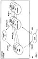
- FIG. 1 is a simplified block diagram of a computer system 900 that implements an embodiment of the extended MVC design pattern.
- the extended MVC design pattern provides a context as a structured storage place for data that relates to a controller.
- a context instance 304 relates (dashed line) to a controller instance 302. Context instances and controller instances will be referred to as contexts and controllers, respectively.
- the controller 302 can manipulate a model 301 in response to an interaction of a user 10 with the computer system 900. There can be further controllers (e.g., further controllers 302-a, 302-b, 302-c) for manipulating the same model 301.
- the further controllers can have further contexts 304-a, 304-b, 304-c that relate (dashed lines) to the further controllers, respectively.
- the model 301 can have multiple views (e.g., views 303, 303-a, 303-b) that present the model to the user 10.
- views 303, 303-a, 303-b When the model 301 gets modified by at least one of its controllers it updates all of its views.
- Each view relates (dashed lines) to a controller.
- controllers e.g., controller 302-c
- a controller can relate to multiple views.
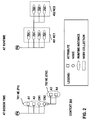
- FIG. 2 illustrates an example of a structure of a context 304 at design time and at runtime.
- structure elements of the design time context structure are different from structure elements of the runtime context structure.
- An example of a design time context structure is a node hierarchy, wherein the structure elements of the node hierarchy can be nodes and attributes.
- the root-node of the node hierarchy represents the context itself.
- the child nodes of the root node can be defined by the application.
- Child nodes of the root node will also be referred to as independent nodes.
- Child nodes of independent nodes depend on their corresponding parent node and will also be referred to as dependent nodes.
- a node has a node type. Examples of node types are value nodes and model nodes.
- a value node can maintain, that is, store and administrate, its own application data (transient application data). The data can be, for example, scalar data, tables or structures.
- a model node includes a reference to a corresponding model that persists application data.
- the parent node can also have attributes.
- Each child node can include an arbitrary tree structure that includes further child nodes and/or attributes. Attributes are leaves in the tree structure. Attributes represent, for example, scalar data types, such as strings and integers or Java types (e.g., java.util.Date).
- the context 304 includes the independent node PN that includes the two attributes A1, A2 and that is the parent node of the dependent nodes CN1, CN2.
- the second dependent node CN2 has two further attributes A3, A4.
- This structure defines a first node element 701 for the parent node PN and a second node element 702 for the second child node CN2.
- the first node element 701 includes information about the context structure with regards to the parent node PN. In other words, it summarizes all information that is available at the context structure level that is under the level of the parent node PN.
- the second node element 702 includes information about the context structure with regards to the second dependent node CN2.
- the context structure implies that the second node element 702 depends on the first node element 701.
- structure elements represent a set of data instances.
- Nodes provide type information about object instances that are maintained by the node.
- Each node can have a node collection, wherein each element of the node collection has the same node element type.
- the parent node PN has a first node collection 401 that includes multiple runtime instances of the first node element 701.
- Each runtime instance of the first node element 701 can have a second node collection 402 of multiple runtime instances of the second node element 702.
- a node collection can be empty or has at least one instance of the corresponding node element.
- a node collection has a cardinality and a node collection type, such as list, tree, set or collection.
- the node collection cardinality (cf. table 2) and the node collection type (cf. table 1) can be declared at design time.
- An evaluation mechanism can be used to automatically evaluate the node collection of a child node at runtime when its parent node changes. Examples of node collection types Value Meaning Collection forward-only iterator (cursor) without absolute positioning Set no duplicates, forward-only iterator without absolute positioning List duplicates allowed, position available, list iterator, absolute positioning (indexed access)
- the application can use the cardinality of a node collection to restrict possible operations on a node (e.g., prohibit indexed access to a node that has at most one node collection element).
- Examples of the cardinality of a node collection Value Meaning 0..1 node collection can be empty, contains at most one element 1..1 node collection always contains exactly one element. 0..n node collection can be empty or contain any number of elements 1..n node collection always contains at least one element.
- the content of a node collection can be determined in various ways.
- the node values of independent nodes can be set by initializers or event handlers or can be set through a supply function.
- the supply function is called when the node is accessed.
- the node is queried for its data by application code or by a user interface (UI) element (of the view) that is bound to the node.
- UI user interface
- Dependent nodes can get their values by using a supply function. For example, the node collection of a dependent node can become obsolete when a selection of its parent node changes. In this case the dependent node is recalculated, that is, the content of its node collection is determined on a subsequent access.
- a representation instance is created for each dependent node of a parent node. The values of the representation instances are calculated when the corresponding parent node is accessed. In other words, using representation instances enables a "load data on demand" or a "unload data when not needed” mechanism. Therefore, memory is used in an efficient manner.
- the content of a node collection can also be explicitly set to a state, such as "invalid" or "unfilled”.
- the node collection content is determined again. This can be used to force a re-read of modified data when the modification (e.g., in the model) was not visible to the application runtime.
- FIG. 3 illustrates the context 304 at runtime as a set of data instances.
- the nodes of the context at runtime represent a framework-managed set of data instances (e.g., a java.sql.RecordSet).
- data instances are returned 50 from a database or backend system 901 in response to a query (e.g., a structured query language (SQL) query) that is sent 40 from the computer system 900 to the database/backend system 901 when a node is accessed, for example, by an application.
- SQL structured query language
- backend systems are Enterprises Resource Planning systems, Customer Relationship Management systems, web server systems providing web services or any other system that stores application data. Accessing a node means requesting data from the corresponding model.
- Nodes provide type information about object instances that are maintained by the node.
- the type information can also be derived from the model. For example, if the parent node PN corresponds to a customer, its node collection 401 can include all orders for this customer.
- the computer system 900 can sent 40 a query to retrieve all orders of the customer from the corresponding database/backend system 901, such as a sales and distribution (SD) system or a customer relationship management (CRM) system.
- SD sales and distribution
- CRM customer relationship management
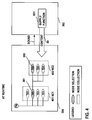
- FIG. 4 illustrates an example of a node selection 501 within the context 304 at runtime.
- a node PN can maintain a node selection 501 within a node collection 401. Node selections are illustrated in FIG. 4 by a grid pattern for each element of the node collection that belongs to the node selection.
- the node selection 501 is a designated subset (one or more elements) of the node collection 401 of the node PN.
- the node selection 501 has a cardinality that is controlled by the cardinality of the selected nodes declared at design time (cf. table 3, below).
- One specific element that plays a special role amongst the elements of the node selection will be referred to as the lead selection element.
- the first node collection 401 can include all orders of the customer.
- the lead selection of the node collection can be by default the first order of the customer.
- the second node collection 402 can include all order items of the selected order. Examples of the cardinality of a node selection in dependence of the node (collection) cardinalities of the corresponding node elements of the selection Value Meaning Node Cardinality 0..1 single selection ( ⁇ lead selection), can be empty Any 1..1 single selection ( ⁇ lead selection), always contains one element only 1..1, 1..n 0..n multiple selection; can be empty; if not empty one element is designated as the "lead selection" only 0..n, 1..n 1..n multiple selection. One selected element is designated as the "lead selection" only 1..n
- the lead selection element can be accessed from controller code.
- UI elements can be bound against the attributes of the lead selection element and the content of a child node depends on the lead selection element of its parent node.
- the node selection 501 can correspond to a selection that results from an user action (e.g., the user selects the second order out of a list of orders.) This automatically triggers an update of the second node collection 402 with, for example, all order items of the second order.
- the second node collection 402 can have a further node selection 502.
- a node selection can also include multiple elements of the corresponding node collection.
- Node selection and lead selection element are bindable node properties in the sense that UI elements can represent a node selection (e.g., as selected lines in a table control) and also modify it (e.g., selecting/deselecting an item in a table control adds/removes the corresponding element to/from the node selection).
- Node selections can exist on their own. A selection made by a user can be represented as a node selection and a node selection can be visualized in a UI element.
- a context can include a flat set of child nodes (independent nodes) each one independent from the others. Each independent node can have further child nodes (dependent nodes). While the content of independent nodes can be defined by the application, the content of a dependent node depends on the lead selection element of its parent node. The application defines how the content of the dependent node depends on the parent node's lead selection element by specifying a corresponding supply function. For example, a supply function can be used in case a specific order (e.g., node selection 501) of a customer is selected and only order items that are not on stock should be included in the second node collection 402. In other words, the relationships between data that are declared in the context 304 at design time can be used to filter data at runtime.
- a supply function can be used in case a specific order (e.g., node selection 501) of a customer is selected and only order items that are not on stock should be included in the second node collection 402.
- the supply function can be defined in such a way that it always returns the same value for the same selected node element and does not take into account changes in the returned data.
- the application runtime can decide not to call a supply function again with the same arguments when it is called a second time within the lifetime of the application.
- a parent node e.g., an order
- the content of all of its child nodes e.g., order items
- its content is determined again, for example, by calling a corresponding supply function 601 to supply content for the node.
- Supply functions can be declared as methods in the corresponding controller 302.
- the following pseudo code shows an example of the signature of a supply function: Pseudo code example: Collection supplyFunction(Node node, NodeElement parentElement);
- program code is generated that calls the declared method when content for a node is to be supplied 60.
- Embodiments of a supply function can have one or more of the following features:
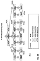
- FIGS. 5A and 5B illustrate two alternative runtime implementations of context node data instances of a context 304-a.
- a dependent node e.g., node B
- node B can be represented as a single node instance whose node collection changes whenever the parent node's (e.g., node A) node collection or lead selection element changes.
- content node collection
- Static binding means that the node binds to a "class" of the node instead of binding to a named node instance.
- a node according to the first implementation will be referred to as a singleton node.
- FIG. 5A shows an example of a context structure of context 304-a at design time.
- Node A has a node element NE(A)
- node B has a node element NE(B)
- node C has a node element NE(C), wherein each element includes child nodes and/or attributes.
- a node collection NC(B) of node element NE(B) instances is only maintained for the lead selection of the node collection NC(A).
- a node collection NC (C) of node element NE (C) instances is only maintained for the lead selection of the node collection NC(B).
- a single node instance of the node (e.g., node B) exists for each instance in the parent node collection (e.g., node collection NC(A)). All single node instances can be accessed directly.
- a runtime implementation can create and fill single node instances lazily (by loading data on demand) to reduce resource usage.
- an application can also access data of child nodes that do not correspond to the parent node's lead selection element (e.g., read address fields for business partner No. 5 instead of the address fields for the currently selected business partner No. 3).
- a dependent node according to the second implementation will be referred to as a non-singleton node.
- FIG. 5B is based on the context structure 304-a at design time as described under FIG. 5A. It shows an example of a runtime structure of context 304-a according to the second implementation.
- Each instance in node collection NC(A) can have a node collection NC1(B) to NC3(B). Further, each instance of node collections NC1(B) to NC3(B) can have a node collection NC1(C) to NC5(C) . Empty node collections are not shown in the example.
- the information if a node is a singleton or non-singleton node can be stored in a node property "singleton" (cf. table 4, below).
- a non-singleton node acts as the parent node of a singleton node
- the singleton node is not a singleton node with regards to the context. That is, for each instance of the non-singleton parent node there exists one instance of the singleton child node. If the child node is a singleton node with regards to the context, then its parent node may change depending on its grandparent node's lead selection element.
- a framework keeps references to all created instances of a child node until the parent node's collection changes. This enables a client in a client-server computer system to remember data from previously received child node instances and modify this data later.
- node property singleton Value Meaning True a single instance of the node exists per parent node and the content of the node changes when the parent node's lead selection element changes. False one instance of the node exists per node element in the parent node's node collection. The content of an instance does not change.
- API application programming interface
- parent node is a singleton node, only a single instance exists and can be accessed and its content depends on the parent node's node collection and lead selection element.
- a tree structure is declared including an independent node "Customers” that has a child node “Orders” and the child node “Orders” has a further child node “OrderItems”.
- Customer can have multiple orders and each order can have multiple items. This is reflected in a corresponding context by declaring child nodes belonging to each element of the parent node so that each element has a collection of its own.
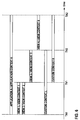
- FIG. 6 illustrates an example of context lifetimes for various context types.
- controllers There are at least two types of controllers and correspondingly two types of contexts: view controllers/view contexts and custom controllers/custom contexts.
- a view controller relates to a corresponding view.
- the lifetime of the view controller equals the lifetime of the corresponding view, that is, the time the view is displayed.
- a view context relates to the view controller and has the same lifetime.
- UI elements of the view can bind to the view context.
- an application e.g., APPLICATION A
- typically a sequence of multiple views e.g., VIEW 1, VIEW 2, VIEW 3, VIEW 4
- the user interacts with the application program through the various views.
- the various views can raise events that cause the related view controllers to determine which view is presented when and where. That is, some views and, therefore, the related view contexts can have a short lifetime.
- APPLICATION A starts at TA1 and ends at TA2.
- VIEW 1 and VIEW 2 are presented to the user simultaneously.
- the corresponding view controllers determine that the presentation of VIEW 1 and VIEW 2 needs to be replaced by a presentation of VIEW 3.
- the corresponding view controllers determine that the presentation of VIEW 3 needs to be replaced by a presentation of VIEW 4.
- the views VIEW 1 to VIEW 4 relate to the view contexts VIEW CONTEXT 1 to VIEW CONTEXT 4. That is, the data that is stored in each view context has the same lifetime as the view that binds to the data.
- a custom context relates to a custom controller of the model.
- a custom controller is implemented as view independent, application process oriented coding.
- the lifetime of a custom context can be defined in such a way that it spans the lifetime of multiple views.
- CUSTOM CONTEXT I is defined to span the lifetime of the views VIEW 1 to VIEW 3.
- CUSTOM CONTEXT II is defined to span the lifetime of the views VIEW 3 and VIEW 4.
- a specific example of a custom context is an application context, which lives over the lifetime of the application, that is, over the sequence of all views of the application.
- the application decides about its lifetime
- a framework can decide about the lifetime of the application context because the framework knows when an application starts (TA1) and when it ends (TA2). Therefore, the framework can control an application controller that is assigned to the application context.
- FIG. 7 illustrates mapping of contexts according to the present invention.
- UI elements e.g., UI elements 951, 952 of views (e.g., VIEW 1, VIEW 2) that are used in a user interface (UI) 950 bind 81, 82 to view contexts (e.g., VIEW CONTEXT 1, VIEW CONTEXT 2) and long living data can reside in custom contexts (e.g., CUSTOM CONTEXT I)
- an embodiment of the present invention enables mapping 91, 92 of nodes/attributes of view contexts or custom contexts to nodes/attributes of custom contexts.
- nodes and attributes of view contexts or custom contexts can reference type-compatible nodes and attributes in other custom contexts. Nodes can also be mapped to other nodes within the same context.
- Node mapping reduces the need for copying data between several contexts by enabling a node N1 of a first context (e.g., a view context, such as VIEW CONTEXT 2, or a custom context) to reference 91 a node N1' of a second context (e.g., a custom context, such as CUSTOM CONTEXT I, or an application context), where the node N1' of the second context has or references the data.
- a first context e.g., a view context, such as VIEW CONTEXT 2, or a custom context
- a second context e.g., a custom context, such as CUSTOM CONTEXT I, or an application context
- mapping contexts can span multiple context levels. That is, a custom context can reference a further custom context. Therefore, context hierarchies can be created (cf. FIG. 9).
- related data can be collected in a dedicated custom context.
- the binding to this data is implemented by using a view context that is mapped to the custom context accordingly.
- the extended MVC pattern enables an application developer to quickly modify an application while maintaining consistency of the application. For example, in some cases rearrangement of views or UI elements can be achieved without modifying the corresponding controller code. This provides a way for an application developer to better structure applications in light of potential functional enhancements or changes. For example, reusing a field that already exists on one view in other views can be achieved by defining the corresponding mapping while the corresponding controller code stays valid.
- node M maps its node collection to node O's node collection.
- the node selections of nodes M and O can be mapped.
- Node M can also maintain its own node selection on node O's node collection.
- the node collection cardinality of node M equals that of node O (e.g., by inheritance).
- the selection cardinality can be inherited from origin node O.
- Node M can override the node cardinality inherited from node O.
- node M is a singleton node, too. If node O is a non-singleton node, node M can be a singleton or non-singleton node. If node M is a non-singleton node it shares the same parent node collection with node O. If node M is a singleton node, then the collection of node M follows the instance of node O that belongs to the lead selection of node O's parent node.
- the content of the node collection can be defined by the node collection of the origin node.
- An independent node can always be mapped. It can be mapped to any other node in the same context or to any other node in another custom context (as long as no cycle is formed with regards to parent-child and mapping relationships).
- a child node of a mapped node can be unmapped. In this case its content can be determined by the supply function mechanism.
- a child node of the parent node can be mapped to a further child node of the further parent node.
- node W is a child of node X and node Y is a child of node Z
- node W can be mapped to node Y if node X is mapped to node Z.
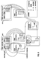
- FIG. 8 illustrates a third, specific example of mapping contexts.
- Two windows 950-1, 950-2 can be displayed at runtime on a client of a client-server system.
- the windows are part of a user interface of an application and are displayed on a conventional display device (e.g., monitor) of the client.
- a page that is displayed may include one or more view assemblies.
- the first window 950-1 displays view assembly MAIN that includes view A and view B.
- the second window displays view assembly POP UP that includes view D.
- the views in the view assemblies include UI elements which are bound to the view contexts of the corresponding views. The binding is illustrated by bended arrows with a bullet point at the origin of the arrows.
- UI elements of views A, B, D are bound to view contexts A, B, D, respectively.
- the UI element in view A is a table having two columns.
- the four UI elements of view B can be display/input fields that have a relationship to the table of view A.
- the UI elements of view D correspond to a title of the pop up and four further input/display fields.
- the view contexts A, B, D include node/attribute hierarchies for maintaining the data of the corresponding view.
- Nodes and attributes can derive their state from nodes/attributes of custom contexts (e.g., custom contexts 1, 2) that belong to controllers (e.g., custom or application controllers) other than the corresponding view controllers. This enables maintenance of the data without redundancies. Further, it can be used for a method for synchronizing data dependencies amongst multiple views.
- view context A and view context B include one independent node each, which is illustrated as the top-level node of the corresponding context structure.
- the independent node of view A holds information about which record set is to be used for the table and about the current position within the record set. Both independent nodes are mapped to the corresponding independent node in custom context 1.
- view A and view B share a common data source (e.g., the record set) provided by the commonly used node of custom context 1. Therefore, the record set displayed in the table of view A is also used as the underlying record set for view B.
- View A displays two columns of the record set, whereas view B displays three fields of a selected row of the record set. This is represented by the UI elements illustrated by a grid pattern. The three fields in view B can also serve as input fields to update the underlying record set. View B displays a further field not related to the record set.
- Context mapping can also be used to open a menu/list (e.g., view D in the view assembly POP UP), which can display data based on the current selection. No transport code is necessary and no selection parameters need to be passed.
- a menu/list e.g., view D in the view assembly POP UP
- the last two attributes of view context D are mapped to corresponding attributes of custom context 2. Because the last attribute of view context B maps to the same attribute of custom context 2 as the next to last attribute of view context D, the content of the upper input/display field in view B equals the content of the upper input/display field in view D. No transport code for transporting data from view B to view D is necessary to achieve this.
- the last attribute of view context D is mapped to the last attribute of custom context 2 which again is mapped to the next to last attribute of custom context 1.
- Multilevel context hierarchies are useful to package data according to their lifetime because, as explained in reference to FIG. 6, each context can have a different lifetime. Storing data only once in the context hierarchy and using mapping to access the data through multiple levels of the context hierarchy avoids redundant storage of data and, therefore, reduces main memory consumption.
- An embodiment of the present invention can be implemented by using a computer system that has at least a memory and a processor.
- the computer system can communicate with further computer systems over a network (e.g., a wide area network (WAN), a local area network (LAN), the Internet.)
- a computer program product that can be loaded into the memory of the computer system includes instructions that when executed by the processor causes the computer system to perform steps according to the present invention.
- the invention can be implemented in digital electronic circuitry, or in computer hardware, firmware, software, or in combinations of them.
- the invention can be implemented as a computer program product, i.e., a computer program tangibly embodied in an information carrier, e.g., in a machine-readable storage device or in a propagated signal, for execution by, or to control the operation of, data processing apparatus, e.g., a programmable processor, a computer, or multiple computers.
- a computer program can be written in any form of programming language, including compiled or interpreted languages, and it can be deployed in any form, including as a stand-alone program or as a module, component, subroutine, or other unit suitable for use in a computing environment.
- a computer program can be deployed to be executed on one computer or on multiple computers at one site or distributed across multiple sites and interconnected by a communication network.
- Method steps of the invention can be performed by one or more programmable processors executing a computer program to perform functions of the invention by operating on input data and generating output. Method steps can also be performed by, and apparatus of the invention can be implemented as, special purpose logic circuitry, e.g., an FPGA (field programmable gate array) or an ASIC (application-specific integrated circuit).
- FPGA field programmable gate array
- ASIC application-specific integrated circuit
- processors suitable for the execution of a computer program include, by way of example, both general and special purpose microprocessors, and any one or more processors of any kind of digital computer.
- a processor will receive instructions and data from a read-only memory or a random access memory or both.
- the essential elements of a computer are a processor for executing instructions and one or more memory devices for storing instructions and data.
- a computer will also include, or be operatively coupled to receive data from or transfer data to, or both, one or more mass storage devices for storing data, e.g., magnetic, magneto-optical disks, or optical disks.
- Information carriers suitable for embodying computer program instructions and data include all forms of non-volatile memory, including by way of example semiconductor memory devices, e.g., EPROM, EEPROM, and flash memory devices; magnetic disks, e.g., internal hard disks or removable disks; magneto-optical disks; and CD-ROM and DVD-ROM disks.
- semiconductor memory devices e.g., EPROM, EEPROM, and flash memory devices
- magnetic disks e.g., internal hard disks or removable disks
- magneto-optical disks e.g., CD-ROM and DVD-ROM disks.
- the processor and the memory can be supplemented by, or incorporated in special purpose logic circuitry.
- the invention can be implemented on a computer having a display device, e.g., a CRT (cathode ray tube) or LCD (liquid crystal display) monitor, for displaying information to the user and a keyboard and a pointing device, e.g., a mouse or a trackball, by which the user can provide input to the computer.
- a display device e.g., a CRT (cathode ray tube) or LCD (liquid crystal display) monitor
- a keyboard and a pointing device e.g., a mouse or a trackball
- Other kinds of devices can be used to provide for interaction with a user as well; for example, feedback provided to the user can be any form of sensory feedback, e.g., visual feedback, auditory feedback, or tactile feedback; and input from the user can be received in any form, including acoustic, speech, or tactile input.
- the invention can be implemented in a computing system that includes a back-end component, e.g., as a data server, or that includes a middleware component, e.g., an application server, or that includes a front-end component, e.g., a client computer having a graphical user interface or a Web browser through which a user can interact with an implementation of the invention, or any combination of such back-end, middleware, or front-end components.
- the components of the system can be interconnected by any form or medium of digital data communication, e.g., a communication network. Examples of communication networks include a local area network ("LAN”) and a wide area network (“WAN”), e.g., the Internet.
- LAN local area network
- WAN wide area network
- the computing system can include clients and servers.
- a client and server are generally remote from each other and typically interact through a communication network.
- the relationship of client and server arises by virtue of computer programs running on the respective computers and having a client-server relationship to each other.
Landscapes
- Engineering & Computer Science (AREA)
- Software Systems (AREA)
- General Engineering & Computer Science (AREA)
- Theoretical Computer Science (AREA)
- Physics & Mathematics (AREA)
- General Physics & Mathematics (AREA)
- Human Computer Interaction (AREA)
- Information Retrieval, Db Structures And Fs Structures Therefor (AREA)
- Stored Programmes (AREA)
- User Interface Of Digital Computer (AREA)
Priority Applications (1)
| Application Number | Priority Date | Filing Date | Title |
|---|---|---|---|
| US10/676,836 US6952620B2 (en) | 2002-09-30 | 2003-09-30 | Declaring application data |
Applications Claiming Priority (2)
| Application Number | Priority Date | Filing Date | Title |
|---|---|---|---|
| US41498502P | 2002-09-30 | 2002-09-30 | |
| US414985P | 2002-09-30 |
Publications (2)
| Publication Number | Publication Date |
|---|---|
| EP1406170A2 true EP1406170A2 (de) | 2004-04-07 |
| EP1406170A3 EP1406170A3 (de) | 2006-11-02 |
Family
ID=31994274
Family Applications (3)
| Application Number | Title | Priority Date | Filing Date |
|---|---|---|---|
| EP02024244A Ceased EP1406170A3 (de) | 2002-09-30 | 2002-10-31 | Rechnersystem zum Deklarieren von Anwendungsdaten |
| EP02024242A Ceased EP1406168A3 (de) | 2002-09-30 | 2002-10-31 | Rechnersystem und Verfahren zur Verwendung von verknüpften Daten während der Laufzeit |
| EP02024243A Ceased EP1406169A3 (de) | 2002-09-30 | 2002-10-31 | Rechnersystem und Verfahren zur Verwendung von Beziehungen zwischen Kontexten |
Family Applications After (2)
| Application Number | Title | Priority Date | Filing Date |
|---|---|---|---|
| EP02024242A Ceased EP1406168A3 (de) | 2002-09-30 | 2002-10-31 | Rechnersystem und Verfahren zur Verwendung von verknüpften Daten während der Laufzeit |
| EP02024243A Ceased EP1406169A3 (de) | 2002-09-30 | 2002-10-31 | Rechnersystem und Verfahren zur Verwendung von Beziehungen zwischen Kontexten |
Country Status (2)
| Country | Link |
|---|---|
| US (1) | US6952620B2 (de) |
| EP (3) | EP1406170A3 (de) |
Cited By (1)
| Publication number | Priority date | Publication date | Assignee | Title |
|---|---|---|---|---|
| US9239737B2 (en) | 2013-11-15 | 2016-01-19 | Sap Se | Concise resource addressing |
Families Citing this family (17)
| Publication number | Priority date | Publication date | Assignee | Title |
|---|---|---|---|---|
| US7600215B2 (en) * | 2002-09-30 | 2009-10-06 | Sap Ag | Using interrelated data at run time |
| US7069537B2 (en) * | 2003-08-19 | 2006-06-27 | Oracle International Corporation | Techniques for partial loading of a configuration associated with a configuration model |
| US7590614B2 (en) * | 2003-12-11 | 2009-09-15 | Sap Ag | Method, apparatus, and computer program product for implementing techniques for visualizing data dependencies |
| US20050262453A1 (en) * | 2004-05-21 | 2005-11-24 | Luca Massasso | Modular data management system |
| US7404176B2 (en) * | 2004-06-01 | 2008-07-22 | Sap Ag | Creating and using nested context structures |
| US8346895B2 (en) | 2009-12-21 | 2013-01-01 | Sap Ag | User productivity on-demand services |
| CN102567400B (zh) | 2010-12-31 | 2014-09-03 | 阿里巴巴集团控股有限公司 | 一种实现Web访问的方法和Web服务器 |
| US8655989B2 (en) | 2011-10-14 | 2014-02-18 | Sap Ag | Business network access protocol for the business network |
| US8938734B2 (en) | 2011-12-14 | 2015-01-20 | Sap Se | User-driven configuration |
| US9276825B2 (en) | 2011-12-14 | 2016-03-01 | Sap Se | Single approach to on-premise and on-demand consumption of services |
| US9275365B2 (en) | 2011-12-14 | 2016-03-01 | Sap Se | Integrated productivity services |
| US20130167110A1 (en) * | 2011-12-27 | 2013-06-27 | René Gross | Modeled user interface controllers |
| US8914778B2 (en) * | 2012-11-05 | 2014-12-16 | International Business Machines Corporation | Data placement for execution of an executable |
| US8863099B2 (en) | 2012-11-05 | 2014-10-14 | International Business Machines Corporation | Compilation and placement of instructions in a memory system |
| US9524147B2 (en) | 2013-05-10 | 2016-12-20 | Sap Se | Entity-based cross-application navigation |
| US10282395B2 (en) | 2013-11-15 | 2019-05-07 | Sap Se | Handling timer-based resizing events based on activity detection |
| US9692633B2 (en) | 2013-11-15 | 2017-06-27 | Sap Se | Role-based resource navigation |
Family Cites Families (10)
| Publication number | Priority date | Publication date | Assignee | Title |
|---|---|---|---|---|
| US5815405A (en) * | 1996-03-12 | 1998-09-29 | Xilinx, Inc. | Method and apparatus for converting a programmable logic device representation of a circuit into a second representation of the circuit |
| EP0996058A1 (de) * | 1998-10-19 | 2000-04-26 | International Business Machines Corporation | Verbessertes Darstellungsschema zur Kommunikation zwischen Teilnehmerstationen und Anwendungsprogrammen |
| US6295513B1 (en) * | 1999-03-16 | 2001-09-25 | Eagle Engineering Of America, Inc. | Network-based system for the manufacture of parts with a virtual collaborative environment for design, developement, and fabricator selection |
| US6484180B1 (en) * | 1999-08-02 | 2002-11-19 | Oracle Corporation | Accessing domain object data stored in a relational database system |
| CA2411378A1 (en) * | 2000-06-30 | 2002-01-10 | The Dow Chemical Company | Multi-variable matrix process control |
| US7174533B2 (en) * | 2002-03-14 | 2007-02-06 | Sun Microsystems, Inc. | Method, system, and program for translating a class schema in a source language to a target language |
| US7461382B2 (en) * | 2002-09-30 | 2008-12-02 | Sap Ag | Event handling with action instances for event-driven software application |
| US7600215B2 (en) * | 2002-09-30 | 2009-10-06 | Sap Ag | Using interrelated data at run time |
| US7225424B2 (en) * | 2002-09-30 | 2007-05-29 | Sap Ag | Using relationships between contexts in model view controller design pattern |
| EP1406183A3 (de) * | 2002-10-01 | 2004-04-14 | Sap Ag | Verfahren und System zur Auffrischung von Browserseiten |
-
2002
- 2002-10-31 EP EP02024244A patent/EP1406170A3/de not_active Ceased
- 2002-10-31 EP EP02024242A patent/EP1406168A3/de not_active Ceased
- 2002-10-31 EP EP02024243A patent/EP1406169A3/de not_active Ceased
-
2003
- 2003-09-30 US US10/676,836 patent/US6952620B2/en not_active Expired - Lifetime
Cited By (1)
| Publication number | Priority date | Publication date | Assignee | Title |
|---|---|---|---|---|
| US9239737B2 (en) | 2013-11-15 | 2016-01-19 | Sap Se | Concise resource addressing |
Also Published As
| Publication number | Publication date |
|---|---|
| EP1406168A2 (de) | 2004-04-07 |
| EP1406169A3 (de) | 2006-11-02 |
| EP1406170A3 (de) | 2006-11-02 |
| US20040143815A1 (en) | 2004-07-22 |
| US6952620B2 (en) | 2005-10-04 |
| EP1406168A3 (de) | 2006-11-02 |
| EP1406169A2 (de) | 2004-04-07 |
Similar Documents
| Publication | Publication Date | Title |
|---|---|---|
| US7225424B2 (en) | Using relationships between contexts in model view controller design pattern | |
| US7581204B2 (en) | Dynamic contexts | |
| US6952620B2 (en) | Declaring application data | |
| US7600215B2 (en) | Using interrelated data at run time | |
| US7404176B2 (en) | Creating and using nested context structures | |
| US7590614B2 (en) | Method, apparatus, and computer program product for implementing techniques for visualizing data dependencies | |
| US7844640B2 (en) | Data mapping visualization | |
| US6704743B1 (en) | Selective inheritance of object parameters in object-oriented computer environment | |
| US7409692B2 (en) | Software component architecture | |
| US5987247A (en) | Systems, methods and computer program products for building frameworks in an object oriented environment | |
| US7925719B2 (en) | Object oriented based, business class methodology for generating quasi-static web pages at periodic intervals | |
| JP5065056B2 (ja) | ワークフローを処理するための方法、コンピュータ・プログラム、およびシステム(ワークフロー・システムへのデータ管理動作の統合) | |
| US7007266B1 (en) | Method and software system for modularizing software components for business transaction applications | |
| US20060101442A1 (en) | Reusable software components | |
| EP1460535A2 (de) | Rahmwerk zur Unterstützung Geschäftssofwareanwendungen | |
| US7818682B2 (en) | Modeling editor | |
| US20110022575A1 (en) | System and method of conclusively verifying the correctness of an information system without needing to test every combination of behaviour at run-time | |
| US20030204481A1 (en) | Method and system for visually constructing XML schemas using an object-oriented model | |
| US7730412B2 (en) | System and method for model-based user interface using transformation nodes | |
| KR20120002579A (ko) | 컴퓨팅 장치, 비즈니스 데이터의 획득 방법 및 컴퓨터 판독 가능 저장 매체 | |
| US9600299B2 (en) | Application object framework | |
| US8201147B2 (en) | Generic XAD processing model | |
| US7212212B2 (en) | Context attribute determination | |
| EP0841612A2 (de) | Struktur zur Softwareentwicklung | |
| US20080295065A1 (en) | System and method for resolving interdependencies between heterogeneous artifacts in a software system |
Legal Events
| Date | Code | Title | Description |
|---|---|---|---|
| PUAI | Public reference made under article 153(3) epc to a published international application that has entered the european phase |
Free format text: ORIGINAL CODE: 0009012 |
|
| AK | Designated contracting states |
Kind code of ref document: A2 Designated state(s): AT BE BG CH CY CZ DE DK EE ES FI FR GB GR IE IT LI LU MC NL PT SE SK TR |
|
| AX | Request for extension of the european patent |
Extension state: AL LT LV MK RO SI |
|
| RIN1 | Information on inventor provided before grant (corrected) |
Inventor name: WEIGEL, FRANK Inventor name: RITTER, STEPHAN Inventor name: REEDER, UWE Inventor name: CHERDRON, MARKUS |
|
| RAP1 | Party data changed (applicant data changed or rights of an application transferred) |
Owner name: SAP AG |
|
| PUAL | Search report despatched |
Free format text: ORIGINAL CODE: 0009013 |
|
| AK | Designated contracting states |
Kind code of ref document: A3 Designated state(s): AT BE BG CH CY CZ DE DK EE ES FI FR GB GR IE IT LI LU MC NL PT SE SK TR |
|
| AX | Request for extension of the european patent |
Extension state: AL LT LV MK RO SI |
|
| 17P | Request for examination filed |
Effective date: 20070118 |
|
| 17Q | First examination report despatched |
Effective date: 20070502 |
|
| AKX | Designation fees paid |
Designated state(s): DE FR GB |
|
| STAA | Information on the status of an ep patent application or granted ep patent |
Free format text: STATUS: THE APPLICATION HAS BEEN REFUSED |
|
| 18R | Application refused |
Effective date: 20110603 |