EP1405994B1 - Intake apparatus for internal combustion engine - Google Patents
Intake apparatus for internal combustion engine Download PDFInfo
- Publication number
- EP1405994B1 EP1405994B1 EP20030022572 EP03022572A EP1405994B1 EP 1405994 B1 EP1405994 B1 EP 1405994B1 EP 20030022572 EP20030022572 EP 20030022572 EP 03022572 A EP03022572 A EP 03022572A EP 1405994 B1 EP1405994 B1 EP 1405994B1
- Authority
- EP
- European Patent Office
- Prior art keywords
- intake
- intake port
- region
- recirculation
- passage
- Prior art date
- Legal status (The legal status is an assumption and is not a legal conclusion. Google has not performed a legal analysis and makes no representation as to the accuracy of the status listed.)
- Expired - Lifetime
Links
- 238000002485 combustion reaction Methods 0.000 title claims description 23
- 238000011144 upstream manufacturing Methods 0.000 claims description 37
- 238000005192 partition Methods 0.000 claims description 35
- 230000003134 recirculating effect Effects 0.000 claims description 6
- 238000005728 strengthening Methods 0.000 claims description 5
- 230000003313 weakening effect Effects 0.000 claims 1
- 239000012530 fluid Substances 0.000 description 11
- 230000000052 comparative effect Effects 0.000 description 8
- 230000003247 decreasing effect Effects 0.000 description 4
- 239000000446 fuel Substances 0.000 description 3
- 238000005266 casting Methods 0.000 description 2
- 239000000203 mixture Substances 0.000 description 2
- 230000001419 dependent effect Effects 0.000 description 1
- 238000010586 diagram Methods 0.000 description 1
- 230000000694 effects Effects 0.000 description 1
- 238000002347 injection Methods 0.000 description 1
- 239000007924 injection Substances 0.000 description 1
- 239000002184 metal Substances 0.000 description 1
Images







Classifications
-
- F—MECHANICAL ENGINEERING; LIGHTING; HEATING; WEAPONS; BLASTING
- F02—COMBUSTION ENGINES; HOT-GAS OR COMBUSTION-PRODUCT ENGINE PLANTS
- F02M—SUPPLYING COMBUSTION ENGINES IN GENERAL WITH COMBUSTIBLE MIXTURES OR CONSTITUENTS THEREOF
- F02M35/00—Combustion-air cleaners, air intakes, intake silencers, or induction systems specially adapted for, or arranged on, internal-combustion engines
- F02M35/10—Air intakes; Induction systems
- F02M35/10091—Air intakes; Induction systems characterised by details of intake ducts: shapes; connections; arrangements
- F02M35/10098—Straight ducts
-
- F—MECHANICAL ENGINEERING; LIGHTING; HEATING; WEAPONS; BLASTING
- F02—COMBUSTION ENGINES; HOT-GAS OR COMBUSTION-PRODUCT ENGINE PLANTS
- F02B—INTERNAL-COMBUSTION PISTON ENGINES; COMBUSTION ENGINES IN GENERAL
- F02B31/00—Modifying induction systems for imparting a rotation to the charge in the cylinder
-
- F—MECHANICAL ENGINEERING; LIGHTING; HEATING; WEAPONS; BLASTING
- F02—COMBUSTION ENGINES; HOT-GAS OR COMBUSTION-PRODUCT ENGINE PLANTS
- F02B—INTERNAL-COMBUSTION PISTON ENGINES; COMBUSTION ENGINES IN GENERAL
- F02B31/00—Modifying induction systems for imparting a rotation to the charge in the cylinder
- F02B31/08—Modifying induction systems for imparting a rotation to the charge in the cylinder having multiple air inlets
- F02B31/085—Modifying induction systems for imparting a rotation to the charge in the cylinder having multiple air inlets having two inlet valves
-
- F—MECHANICAL ENGINEERING; LIGHTING; HEATING; WEAPONS; BLASTING
- F02—COMBUSTION ENGINES; HOT-GAS OR COMBUSTION-PRODUCT ENGINE PLANTS
- F02F—CYLINDERS, PISTONS OR CASINGS, FOR COMBUSTION ENGINES; ARRANGEMENTS OF SEALINGS IN COMBUSTION ENGINES
- F02F1/00—Cylinders; Cylinder heads
- F02F1/24—Cylinder heads
- F02F1/42—Shape or arrangement of intake or exhaust channels in cylinder heads
- F02F1/4214—Shape or arrangement of intake or exhaust channels in cylinder heads specially adapted for four or more valves per cylinder
-
- F—MECHANICAL ENGINEERING; LIGHTING; HEATING; WEAPONS; BLASTING
- F02—COMBUSTION ENGINES; HOT-GAS OR COMBUSTION-PRODUCT ENGINE PLANTS
- F02M—SUPPLYING COMBUSTION ENGINES IN GENERAL WITH COMBUSTIBLE MIXTURES OR CONSTITUENTS THEREOF
- F02M35/00—Combustion-air cleaners, air intakes, intake silencers, or induction systems specially adapted for, or arranged on, internal-combustion engines
- F02M35/10—Air intakes; Induction systems
- F02M35/10209—Fluid connections to the air intake system; their arrangement of pipes, valves or the like
- F02M35/10222—Exhaust gas recirculation [EGR]; Positive crankcase ventilation [PCV]; Additional air admission, lubricant or fuel vapour admission
-
- F—MECHANICAL ENGINEERING; LIGHTING; HEATING; WEAPONS; BLASTING
- F02—COMBUSTION ENGINES; HOT-GAS OR COMBUSTION-PRODUCT ENGINE PLANTS
- F02M—SUPPLYING COMBUSTION ENGINES IN GENERAL WITH COMBUSTIBLE MIXTURES OR CONSTITUENTS THEREOF
- F02M35/00—Combustion-air cleaners, air intakes, intake silencers, or induction systems specially adapted for, or arranged on, internal-combustion engines
- F02M35/10—Air intakes; Induction systems
- F02M35/10242—Devices or means connected to or integrated into air intakes; Air intakes combined with other engine or vehicle parts
- F02M35/10255—Arrangements of valves; Multi-way valves
-
- F—MECHANICAL ENGINEERING; LIGHTING; HEATING; WEAPONS; BLASTING
- F02—COMBUSTION ENGINES; HOT-GAS OR COMBUSTION-PRODUCT ENGINE PLANTS
- F02M—SUPPLYING COMBUSTION ENGINES IN GENERAL WITH COMBUSTIBLE MIXTURES OR CONSTITUENTS THEREOF
- F02M35/00—Combustion-air cleaners, air intakes, intake silencers, or induction systems specially adapted for, or arranged on, internal-combustion engines
- F02M35/10—Air intakes; Induction systems
- F02M35/10242—Devices or means connected to or integrated into air intakes; Air intakes combined with other engine or vehicle parts
- F02M35/10262—Flow guides, obstructions, deflectors or the like
-
- F—MECHANICAL ENGINEERING; LIGHTING; HEATING; WEAPONS; BLASTING
- F02—COMBUSTION ENGINES; HOT-GAS OR COMBUSTION-PRODUCT ENGINE PLANTS
- F02M—SUPPLYING COMBUSTION ENGINES IN GENERAL WITH COMBUSTIBLE MIXTURES OR CONSTITUENTS THEREOF
- F02M35/00—Combustion-air cleaners, air intakes, intake silencers, or induction systems specially adapted for, or arranged on, internal-combustion engines
- F02M35/10—Air intakes; Induction systems
- F02M35/104—Intake manifolds
- F02M35/108—Intake manifolds with primary and secondary intake passages
- F02M35/1085—Intake manifolds with primary and secondary intake passages the combustion chamber having multiple intake valves
-
- F—MECHANICAL ENGINEERING; LIGHTING; HEATING; WEAPONS; BLASTING
- F02—COMBUSTION ENGINES; HOT-GAS OR COMBUSTION-PRODUCT ENGINE PLANTS
- F02B—INTERNAL-COMBUSTION PISTON ENGINES; COMBUSTION ENGINES IN GENERAL
- F02B1/00—Engines characterised by fuel-air mixture compression
- F02B1/02—Engines characterised by fuel-air mixture compression with positive ignition
- F02B1/04—Engines characterised by fuel-air mixture compression with positive ignition with fuel-air mixture admission into cylinder
-
- Y—GENERAL TAGGING OF NEW TECHNOLOGICAL DEVELOPMENTS; GENERAL TAGGING OF CROSS-SECTIONAL TECHNOLOGIES SPANNING OVER SEVERAL SECTIONS OF THE IPC; TECHNICAL SUBJECTS COVERED BY FORMER USPC CROSS-REFERENCE ART COLLECTIONS [XRACs] AND DIGESTS
- Y02—TECHNOLOGIES OR APPLICATIONS FOR MITIGATION OR ADAPTATION AGAINST CLIMATE CHANGE
- Y02T—CLIMATE CHANGE MITIGATION TECHNOLOGIES RELATED TO TRANSPORTATION
- Y02T10/00—Road transport of goods or passengers
- Y02T10/10—Internal combustion engine [ICE] based vehicles
- Y02T10/12—Improving ICE efficiencies
Definitions
- the present invention relates to an intake apparatus for an internal combustion engine and to an internal combustion engine, and more specifically to an intake apparatus including an intake port for increasing incylinder gas motion such as tumble or swirl.
- Gas motion in engine cylinder such as tumble or swirl is important to achieve stable combustion of diluted air/fuel mixture in a spark ignition internal combustion engine. Accordingly, engines of some types require an intake system which can increase incylinder gas motion in wider engine operating region.
- a published Japanese Patent Application Kokai Publication No. 2002-54535 shows a gas motion control valve to increase incylinder gas flow by closing a half of the section of an intake port.
- a published Japanese Patent Application Kokai Publication No. H06(1994)-159079 shows an intake system including a partition dividing an intake port into upper and lower halves, and a gas motion control valve closing the lower half of the intake port, to increase a tumble ratio.
- Such a gas motion control valve is arranged to produce an incylinder tumbling flow by decreasing an open area ratio that is a ratio of an effective flow passage sectional area to an entire flow passage area of an intake port.
- an open area ratio that is a ratio of an effective flow passage sectional area to an entire flow passage area of an intake port.
- an internal combustion engine injecting fuel into the intake air stream prior entering the combustion chamber via the inlet valves, wherein an intake recirculation passage is provided, which is configured to recirculate part of the intake air from a more downstream region in the intake passage to a more upstream region of the intake passage in order to facilitate mixture of air and fuel in the air intake passage.
- the sidewall of the air intake pipe is provided with an orifice, wherein intake air flowing over the orifice "produces" suction towards the intake passage.
- a further opening is provided inside the sidewall, which is in communication with the intake passage such that reverse flow in the intake passage enters the opening.
- said opening and said orifice are communicating with each other via a connecting passage, wherein suction produced in the orifice is communicated through the connecting passage to the opening such that reverse flow is "pumped" to the orifice and reenters the intake passage via the orifice.
- FIG. 1 shows part of an internal combustion engine having an intake apparatus in a first practical example according to a first embodiment.
- the engine of this example is an incylinder direct injection spark ignition engine.
- the intake apparatus or system is designed to strengthen an incylinder gas motion which, in this example, is tumble.
- an intake air recirculation passage is external to an intake port, unlike a second embodiment.
- a cylinder block 1 is formed with a plurality of cylinders 2 having a cylindrical shape.
- a cylinder head 3 closes the upper ends of the cylinders 2.
- Cylinder head 3 is formed with a plurality of recesses each defining a combustion chamber 4.
- combustion chamber 4 of each cylinder is of the pentroof type, and having two sloping surfaces.
- an intake port 5 extends to a downstream end opening in one of the two sloping surfaces of combustion chamber 4.
- An exhaust port 6 opens in the other sloping surface of combustion chamber 4.
- An intake valve 7 shown in FIG. 1 is arranged to open and close the downstream end of intake port 5.
- An exhaust valve 8 is arranged to open and close the end of exhaust port 6.
- a downstream end portion of intake port 5 is bifurcated, and has two branches each opening into combustion chamber 4. Accordingly, each cylinder has two intake valves 7 for opening and closing the downstream ends of two branches of intake port 5. Similarly, each cylinder has two exhaust valves 8. A spark plug 9 is provided at the center of combustion chamber surrounded by these four valves 7 and 8.
- a piston 10 is received in each cylinder 2.
- piston 10 is shown to have a flat top. However, the piston crown may be designed to have various shapes according to various requirements, such as requirement for stratified charge combustion. In an up-down (axial) direction of each cylinder, piston 10 moves upward toward spark plug 9, and moves downward away from spark plug 9.
- a throttle valve 11 of a butterfly type is provided in intake port 5.
- This example employs a multi-throttle arrangement, and there are provided a plurality of throttle valves 11 each for a unique one of the cylinders 4.
- throttle valve 11 includes a disk-shaped valve element 11b mounted on a rotatable valve shaft 11a extending in the direction of the cylinder row.
- the upper half of valve element 11b swings to the downstream side and the lower half of valve element 11b swings to the upstream side in intake port 5.
- valve element 11b is so inclined as to guide the intake air stream to the upper side as viewed in FIG. 1 .
- Intake port 5 is an air passage which may be formed only in cylinder head 3.
- intake port 5 may be formed in cylinder head 3 and an external member, such as an intake manifold, fixed to cylinder head 3.
- throttle valve 11 is installed in an external member external to cylinder head 3.
- the external member has a passage serving as a part of intake port 5.
- intake port 5 is not necessarily formed only in cylinder head 3.
- a recirculation inlet 15 is opened in a lower inside wall surface 5a of intake port 5, and designed to take in intake air flowing in intake port 5.
- a tubular member (serving as a recirculating section) defining a recirculation passage 16 is external to intake port 5, and one end of the tubular member is connected with recirculation inlet 15.
- Recirculation inlet 15 may be a hole such as a circular hole; or may be a plurality of holes arranged in the direction of the cylinder row (in a direction perpendicular to the longitudinal direction of intake port 5); or may be a slit elongated in the direction of the cylinder row.
- Recirculation inlet 15 is located near intake valve 7, and located at a downstream position as close as intake valve 7.
- Recirculation passage 16 extends from recirculation inlet 15, along intake port 5 toward the upstream of intake port 5, and a recirculation outlet section which opens, as a recirculation outlet 17, in intake port 5 at a position slightly downstream of throttle valve 11.
- the recirculation outlet section is in the form of a tube, and projects into intake port 5, toward an upper inside wall surface 5b of intake port 5, as shown in FIG. 1 .
- Recirculation outlet 17 opens toward upper inside wall surface 5b, at a position just downstream of the upper half of valve element 11b of throttle valve 11.
- the thus-constructed intake system is operated as follows: On intake stroke, intake valve 7 is opened and piston 10 descends in the downward direction in cylinder 2. In this case, intake air flows through throttle valve 11, and flows into cylinder 2 through an open aperture around intake valve 7. In the case of part load operation wherein the opening degree of throttle valve 11 is relatively small, throttle valve 11 serves as a flow throttling portion or device, for producing a low pressure region 19 on the downstream side thereof. Recirculation outlet 17 of recirculation passage 16 is opened in this low pressure region 19, and there is formed a pressure difference between recirculation inlet 15 and recirculation outlet 17.
- Recirculation outlet 17 discharges the recirculation air into the upper region in intake port 5 toward the upper inside wall surface 5b, and thereby strengthens the intake air stream in the upper region.
- recirculation outlet 17 discharges the recirculation air upwards toward upper inside wall surface 5b, and thereby acts to press the intake air stream onto the upper inside wall surface 5b. Therefore, most of intake air flows along upper inside wall surface 5b to intake valve 7.
- the intake flow rate is smaller and the flow velocity is lower in a lower portion 20a of the open aperture between intake valve 7 and the outer circumference of the cylinder 2.
- an upper portion 20b of the aperture formed between intake valve 7 and spark plug 9 the intake flow rate is great and the flow velocity is high.
- This intake apparatus can promote the tumble in the cylinder effectively, by strengthening the upper intake flow stream, and on the other hand by reducing the lower intake stream flowing along the lower inside wall surface 5a, into cylinder 2 in such direction as to impede the incylinder tumbling motion.
- the intake system according to the first embodiment is designed to strengthen the tumble (vertical swirl).
- the intakes system according to the first embodiment can be used for strengthening swirl (horizontal swirl) in cylinder 2 by changing the positions and orientations of recirculation inlet 15 and outlet 17.
- the intake system may be arranged to strengthen a swirling motion in an oblique plane by combining tumbling motion and swirling motion.
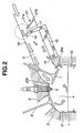
- FIG. 2 shows an intake apparatus in a second practical example according to the first embodiment.
- the intake apparatus of FIG. 2 is substantially identical to the apparatus of FIG. 1 in most aspects as shown by the use of the same reference numerals.
- the second practical example employs, in place of throttle valve 11, a gas motion control valve 21 provided for each cylinder, to close a part of the sectional fluid passage area of intake port 5.
- a throttle valve (not shown in FIG. 2 ) is provided on the upstream side in the intake passage.
- Gas motion control valve 21 includes a plate-shaped valve element 21b mounted on a rotatable valve shaft 21a extending in the direction of the cylinder row.
- the upper half of valve element 21b is partly cut out so as to hold the upper portion of intake port 5 open.
- the lower half of valve element 21b can close the lower part of intake port 5.
- Valve shaft 21a is connected with an actuator (not shown).
- Gas motion control valve 21 is controlled to a closed position shown in FIG. 2 in an engine operating situation to strengthen tumble. In an engine operating region such as a high speed high load region where the intake air quantity becomes greater, gas motion control valve 21 is brought to an open position at which valve element 21b extends in the longitudinal direction of intake port 5 (along the flow direction of the intake air).
- valve element 21b When gas motion control valve 21 is opened from the closed position of FIG. 2 to the open position, the lower half of valve element 21b swings to the upstream side. In the closed position shown in FIG. 2 , valve element 21b is slightly inclined so as to guide the intake air toward upper inside wall surface 5b.
- Recirculation inlet 15 and recirculation passage 16 are constructed in the same manner as in the first practical example of FIG. 1 .
- Recirculation outlet 17 is located just behind gas motion control valve 21. The position of recirculation outlet 17 is located immediately downstream of the position of the upper end of valve element 21b in the closed position shown in FIG. 2 .
- gas motion control valve 21 When gas motion control valve 21 is in the closed position of FIG. 2 to close the lower half region in intake port 5, the intake air stream is deflected upward by the sloping surface of gas motion control valve 21, and most of the intake air flows along upper inside wall surface 5b.
- gas motion control valve 21 serves as a deflector and a flow throttling device, and functions to produce a local low pressure region 19 just downstream of gas motion control valve 21. Therefore, recirculation passage 16 having outlet 17 in this low pressure region 19 acts to suck the intake air in intake port 5 from recirculation inlet 15 as in the first practical example of FIG. 1 , recirculates part of the intake air flowing along lower inside wall surface 5a of intake port 5, and discharges the recirculated air toward the upper inside wall surface 5b.
- gas motion control valve 21 is designed to deflect the intake air stream to the upper region along upper inside wall surface 5b, and the recirculation passage 16 removes part of intake air diffused into the lower region after the passage through gas motion control valve 21.
- Recirculation passage 16 can strengthen the tumble effectively in cooperation with gas motion control valve 21.
- the addition of recirculation passage 16 further strengthen the tumbling flow in cylinder 2 by increasing the flow rate difference and flow velocity difference between the intake air stream through lower opening portion 20a on the lower side of intake valve 7, and the intake air stream through upper opening portion 20b on the upper side of intake valve 7.
- the arrangement of FIG. 2 can increase a tumble ratio.
- the recirculation passage 16 makes it possible to set the opening degree of gas motion control valve at a greater value. As a result, the arrangement of FIG. 2 can reduce the air flow resistance, and expands the operating region in which gas motion control valve 21 can be closed.
- FIG. 3 shows an intake apparatus in a third practical example according to the first embodiment.
- a recirculation outlet 17 of a recirculation passage 16 is opened in lower inside wall surface 5a of intake port 5 at a position upstream of a recirculation inlet 15.
- recirculation outlet 17 is in the form of a slit elongated in the direction of the cylinder row, like recirculation inlet 15.
- a gas motion control valve 21 is provided at a position immediately upstream of recirculation outlet 17.
- a valve shaft of gas motion control valve 21 shown in FIG. 3 extends at the level of lower inside wall surface 5a of intake port 5, and supports one end of a swingable valve element 21b. In a closed position shown in FIG.
- valve element 21b stands upright from lower inside wall surface 5a in intake port 5 and closes the lower region in intake port 5. Therefore, gas motion control valve 21 in the closed position produces a low pressure region 19 over the recirculation outlet 17 as shown in FIG. 3 , and causes recirculation passage 16 to recirculate the intake air by sucking intake air from recirculation inlet 15.
- the intake apparatus of FIG. 3 can increase the incylinder tumbling fluid motion as in the preceding examples.
- valve element 21a When gas motion control valve 21 is rotated to the downstream side, to an open position shown by a broken line in FIG. 3 , valve element 21a extends along lower inside wall surface 5a so as not to impede the air flow in intake port 5, and closes the recirculation outlet 17. In the open state, the intake air does not flow into recirculation passage 16, and the intake air can flow smoothly in intake port 5.
- FIG. 4 shows a variation of the third practical example of FIG. 3 .
- a valve element 21b of a gas motion control valve 21 has an end portion 21c bent at a swingable end. End portion 21c is angled at a right angle as a hook.
- valve element 21b projects upright from lower inside wall surface 5a of intake port 5, and bent portion 21c projects downstream. Therefore, in the closed position, bent portion 21c restrains the intake air from flowing around gas motion control valve 21 into the region behind the upright valve element 21b, and promotes the growth of low pressure region 19 to the downstream side.
- the angled end portion 21c is received snugly in the opening of recirculation outlet 17 and gas motion control valve 21 does not impede the flow in intake port 5.
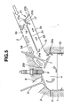
- FIGS. 5 and 6 show a first practical example according to a second embodiment.
- the recirculation passage is not external to the intake port, but the recirculation passage is defined in the intake port by a partition.
- An intake apparatus shown in FIGS. 5 and 6 includes a partition 31 extending in the longitudinal direction of intake port 5 and dividing the cross section of intake port 5 into an upper region and a lower region.
- partition 31 is a metal plate formed as an insert in an operation of casting a cylinder head 3, and completed as an integral part of the casting.
- a downstream end 31a of partition 31 is located near intake valve 7.
- the portion of intake port 5 receiving partition 31 extends straight in the longitudinal direction of intake port 5, and accordingly partition 31 is in the form of a flat plate extending straight in the longitudinal direction of intake port 5.
- intake port 5 may be curved, and partition 31 may be curved along the curved section of intake port 5.
- Partition 31 divides intake port 5 into an upper fluid passage section 5A formed between partition 31 and upper inside wall surface 5b, and a lower fluid passage section 5B formed between partition 31 and lower inside wall surface 5a of intake port 5.
- lower fluid passage section 5B is used as a recirculation passage.
- a gas motion control valve 21 is arranged to open and close an upstream end of lower fluid passage section 5B.
- a valve shaft 21a of gas motion control valve 21 is located on an extension of partition 31 on the upstream side of partition 31. In the example of FIG. 5 , valve shaft 21 is located at a position adjacent to an upstream end 31b of partition 3, on the upstream side of the upstream end 31b of partition 3.
- One end of a valve element 21b is supported by valve shaft 21a.
- valve element 21b In the closed position to close the upstream end of second passage section 5B as shown n FIG. 5 , valve element 21b is so inclined as to guide the intake flow toward upper inside wall surface 5b into the first passage section 5A on the upper side.
- gas motion control valve 21 When gas motion control valve 21 is in the closed position as shown in FIG. 5 , gas motion control valve 21 serves as a flow throttling portion restricting the intake flow to upper passage section 5A, and thereby produces a low pressure region 19 immediately on the downstream side of the upstream partition end 31b.
- a recirculation outlet 17 is opened in an upstream end portion of partition 31 so as to discharge air into the low pressure region 19 formed over recirculation outlet 17.
- Recirculation outlet 17 is formed near upstream end 31b of partition 31.
- recirculation outlet 17 is in the form of a slit extending in the direction of the cylinder row (in a direction perpendicular to the longitudinal direction of intake port 5).
- intake port 5 is divided by partition 31, into upper and lower passage sections to increase tumble.
- partition 31 can be oriented in various ways to strengthen the incylinder swirling fluid flow or to strengthen an incylinder fluid motion intermediate between the tumble and swirl.
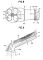
- FIGS. 7 and 8 show a second practical example according to the second embodiment.
- a recirculation outlet 17 is defined as an interspace between the upstream end 31b of a partition 31 and a valve shaft 21a of a gas motion control valve 21.
- a valve element 21b of gas motion control valve 21 includes a main portion for opening and closing the upstream end of lower passage section 5B.
- the valve element 21b further includes an extension portion 21d extending in the opposite direction from valve shaft 21a.
- the extension portion 21d is so shaped and sized to snugly close the recirculation outlet 17 defined between upstream end 31b of partition 31 and valve shaft 21a when gas motion control valve 21 is in the open position in which valve element 21b including extension portion 21d is in alignment with partition 31.
- the projecting length of extension portion 21d is approximately equal to the distance between upstream end 31b of partition 31 and valve shaft 21a.
- valve element 21b including the main portion and extension portion 21d is shaped like a flat plate. In the open position, valve element 21b extends continuously from upstream end 31b of flat partition 31 with almost no clearance, like a continuous flat partition wall.
- FIG. 9 shows the results of analysis of actual intake air flow in an intake apparatus according to the second practical example of the second embodiment.
- the speed and direction of fluid flow in each of points are shown as a vector by a small arrow.
- the density of arrows indicates the flow rate.
- the flow rate is high in a region in which arrows are dense, and low in a region in which arrows are coarse.
- FIG. 10 shows intake air flow in a comparative example in which the recirculation outlet 17 is eliminated.
- the arrangement of FIG. 10 corresponds to an intake system of earlier technology in which the intake air flow is deflected to one side merely by a partition wall 31 and a gas motion control valve 21. In both examples of FIGS. 9 and 10 , the opening degree of gas motion control valve 21 is held at the same value (about 20%).
- FIG. 9 As evident from comparison between FIGS. 9 and 10 , a considerable amount of intake air diffuses downward on the downstream side of the downstream end 31a of partition 31 in the example of FIG. 10 , and flows through the lower open portion 20a on the lower side of intake valve 7 into the cylinder. In lower passage section 5B, the intake air is almost motionless and stagnant. In the case of FIG. 9 , by contrast, intake air is recirculated from a lower region near intake valve 7. Therefore, the intake flow through lower open portion 20a is reduced significantly, and hence the flow through upper open portion 20b is increased correspondingly. Thus, the arrangement of FIG. 9 can increase the incylinder tumble effectively.
- FIGS. 11A and 11B show the results of analysis of the intake air flow rate around intake valve 7.
- the circumference of 360° around intake valve 7 is divided into 8 sectors A ⁇ H of 45°, and the flow rate is plotted for each sector.
- Sectors B ⁇ C correspond to the lower open portion 20a
- sectors F ⁇ G correspond to the upper open portion 20b.
- the flow rate is decreased in B ⁇ C sectors, and the flow rate is increased in sectors F ⁇ G, as compared to a characteristic of the comparative example of FIG. 10 , shown by broken lines in FIG. 11A .
- the flow rate becomes greater in a radial outward direction from the center.
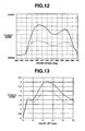
- FIG. 12 shows the results of analysis on a tumble ratio representing the intensity of tumble actually formed in cylinder 2.
- a broken line shows a characteristic in the comparative example of FIG. 10
- a solid line shows a characteristic of the practical example of FIG. 9 according to the second embodiment.
- the intake system according to the second embodiment can increase the tumble ratio for the same open area ratio or opening degree.
- FIG. 13 shows a tumble ratio of tumble formed in cylinder 2 with valve lift in the state in which the pressure difference between the inside of cylinder 2, and the upstream side of gas motion control valve 21 is held constant.
- a broken line shows a characteristic in the comparative example of FIG. 10
- a solid line shows a characteristic of the practical example of FIG. 9 according to the second embodiment.
- the intake system according to the second embodiment can further increase the tumble.
- FIG. 14 shows a relationship between the intensity of tumble and the intake air quantity in an intake system employing partition 31 and gas motion control valve 21 as in the examples of FIG. 9 and FIG. 10 .
- the intensity of tumble is expressed as a maximum value of the tumble ratio during intake stroke.
- the combustion tends to be slow and unstable when the tumble is weak, and the combustion tends to be fast and stable when the tumble is strong.
- a characteristic of the comparative example of FIG. 10 is shown by a solid line curve in FIG. 14 .
- the tumble and the intake air quantity are related to each other in the following manner. As the open area ratio or opening degree is set to a smaller value, the tumble is increased but the intake air quantity becomes smaller.
- a decrease of the intake air quantity means a reduction in the area of a tumble operating region in which tumble can be produced, that is an operating region in which gas motion control valve 21 can be closed.
- an increase of intake air quantity means an increase in the area of increased when the intake air quantity (or the opening degree) is held constant.
- At least cylinder head 3 corresponds to a main section defining an intake port having therein first and second regions extending longitudinally of the intake port.
- External member defining an external recirculation passage or partition 31 corresponds to a recirculating section defining an intake recirculation passage.
- Throttle valve 11 or intake control valve 21 corresponds to a flow throttling section to produce a low pressure region in the upstream portion of the intake port.
- Cylinder block 1 and cylinder head 3 correspond to an engine block member.
- the engine block member may further comprises an external member such as an intake manifold.
- An intake apparatus comprises first means for defining an intake port having therein first and second regions extending longitudinally of the intake port; and second means for defining an intake recirculation passage to recirculate part of intake air from the second region in a downstream end portion of the intake port, to the first region in an upstream portion of the intake port and thereby for strengthening an intake air stream in the first region of the intake port.
- Cylinder head 3 corresponds to the first means, and at least one of items 16, 31, 21 and 11 corresponds to the second means.
Landscapes
- Engineering & Computer Science (AREA)
- Chemical & Material Sciences (AREA)
- Combustion & Propulsion (AREA)
- Mechanical Engineering (AREA)
- General Engineering & Computer Science (AREA)
- Cylinder Crankcases Of Internal Combustion Engines (AREA)
- Exhaust-Gas Circulating Devices (AREA)
Description
- The present invention relates to an intake apparatus for an internal combustion engine and to an internal combustion engine, and more specifically to an intake apparatus including an intake port for increasing incylinder gas motion such as tumble or swirl.
- Gas motion in engine cylinder such as tumble or swirl is important to achieve stable combustion of diluted air/fuel mixture in a spark ignition internal combustion engine. Accordingly, engines of some types require an intake system which can increase incylinder gas motion in wider engine operating region.
- A published Japanese Patent Application Kokai Publication No.
2002-54535 H06(1994)-159079 - Such a gas motion control valve is arranged to produce an incylinder tumbling flow by decreasing an open area ratio that is a ratio of an effective flow passage sectional area to an entire flow passage area of an intake port. However, as the open area ratio becomes smaller, the flow resistance increases, and the amount of intake air that a cylinder can take in becomes smaller. Therefore, an engine operating region in which an incylinder flow is increased by a gas motion control valve is limited to a relatively narrow range.
- From
US 5,662,077 there is known an internal combustion engine injecting fuel into the intake air stream prior entering the combustion chamber via the inlet valves, wherein an intake recirculation passage is provided, which is configured to recirculate part of the intake air from a more downstream region in the intake passage to a more upstream region of the intake passage in order to facilitate mixture of air and fuel in the air intake passage. Therein, the sidewall of the air intake pipe is provided with an orifice, wherein intake air flowing over the orifice "produces" suction towards the intake passage. At a more downstream position of the intake pipe relative to this orifice, a further opening is provided inside the sidewall, which is in communication with the intake passage such that reverse flow in the intake passage enters the opening. Further, said opening and said orifice are communicating with each other via a connecting passage, wherein suction produced in the orifice is communicated through the connecting passage to the opening such that reverse flow is "pumped" to the orifice and reenters the intake passage via the orifice. - It is an objective of the present invention to provide an intake apparatus and an internal combustion engine for increasing incylinder gas motion without decreasing the open area ratio of an intake port excessively.
- This objective is solved in an inventive manner by an intake apparatus having the feature combination of
claim 1 and by an internal combustion engine having the feature combination of claim 13. - Preferred embodiments are laid down in the dependent claims.
- In the following, the present invention is explained in greater detail with respect to several embodiments thereof in conjunction with the accompanying drawings, wherein:
-
FIG. 1 is a sectional view showing an engine with an intake apparatus in a first practical example according to a first embodiment, -
FIG. 2 is a sectional view showing an intake apparatus in a second practical example according to the first embodiment, -
FIG. 3 is a sectional view showing an intake apparatus in a third practical example according to the first embodiment, -
FIG. 4 is a sectional view showing a variation of the third practical example ofFIG. 3 , -
FIG. 5 is a sectional view showing an engine with an intake apparatus in a first practical example according to a second embodiment, -
FIG. 6 is a plan view of the intake apparatus ofFIG. 5 as viewed from above, -
FIG. 7 is a sectional view showing an engine with an intake apparatus in a second practical example according to the second embodiment, -
FIG. 8 is a plan view of the intake apparatus ofFIG. 7 as viewed from above, -
FIGS. 9 and10 are schematic sectional views illustrating intake air streams in an intake port in the example ofFIG. 7 , and in an intake port in a comparative example, -
FIG. 11A is a diagram showing flow distribution around an intake port in the example ofFIG. 7 , andFIG. 11B is a plan view showing eight sectors used inFIG. 11A , -
FIG. 12 is a graph showing a tumble ratio in the example ofFIG. 7 in comparison with the comparative example, -
FIG. 13 is a graph showing a characteristic of the tumble ratio with respect to a valve lift, of the example ofFIG. 7 in comparison with the comparative example,and -
FIG. 14 is a graph showing a relation between the intensity of tumble and the intake air quantity, to illustrate effect of the example ofFIG. 7 . -
FIG. 1 shows part of an internal combustion engine having an intake apparatus in a first practical example according to a first embodiment. The engine of this example is an incylinder direct injection spark ignition engine. The intake apparatus or system is designed to strengthen an incylinder gas motion which, in this example, is tumble. In the first embodiment, an intake air recirculation passage is external to an intake port, unlike a second embodiment. - A
cylinder block 1 is formed with a plurality ofcylinders 2 having a cylindrical shape. Acylinder head 3 closes the upper ends of thecylinders 2.Cylinder head 3 is formed with a plurality of recesses each defining acombustion chamber 4. In this example,combustion chamber 4 of each cylinder is of the pentroof type, and having two sloping surfaces. As shown inFIG. 1 , anintake port 5 extends to a downstream end opening in one of the two sloping surfaces ofcombustion chamber 4. Anexhaust port 6 opens in the other sloping surface ofcombustion chamber 4. Anintake valve 7 shown inFIG. 1 is arranged to open and close the downstream end ofintake port 5. Anexhaust valve 8 is arranged to open and close the end ofexhaust port 6. In this example, a downstream end portion ofintake port 5 is bifurcated, and has two branches each opening intocombustion chamber 4. Accordingly, each cylinder has twointake valves 7 for opening and closing the downstream ends of two branches ofintake port 5. Similarly, each cylinder has twoexhaust valves 8. Aspark plug 9 is provided at the center of combustion chamber surrounded by these fourvalves piston 10 is received in eachcylinder 2. InFIG. 1 ,piston 10 is shown to have a flat top. However, the piston crown may be designed to have various shapes according to various requirements, such as requirement for stratified charge combustion. In an up-down (axial) direction of each cylinder,piston 10 moves upward towardspark plug 9, and moves downward away fromspark plug 9. - A
throttle valve 11 of a butterfly type is provided inintake port 5. This example employs a multi-throttle arrangement, and there are provided a plurality ofthrottle valves 11 each for a unique one of thecylinders 4. As shown inFIG. 1 ,throttle valve 11 includes a disk-shaped valve element 11b mounted on arotatable valve shaft 11a extending in the direction of the cylinder row. In the valve opening operation, the upper half ofvalve element 11b swings to the downstream side and the lower half ofvalve element 11b swings to the upstream side inintake port 5. At an intermediate opening degree as shown inFIG. 1 ,valve element 11b is so inclined as to guide the intake air stream to the upper side as viewed inFIG. 1 . "Upper" means "higher" in position in an axial direction ofcylinder 2 from the position of the crankshaft toward thecombustion chamber 4.Intake port 5 is an air passage which may be formed only incylinder head 3. Alternatively,intake port 5 may be formed incylinder head 3 and an external member, such as an intake manifold, fixed tocylinder head 3. In general,throttle valve 11 is installed in an external member external tocylinder head 3. In this case, the external member has a passage serving as a part ofintake port 5. Thus,intake port 5 is not necessarily formed only incylinder head 3. - A
recirculation inlet 15 is opened in a lowerinside wall surface 5a ofintake port 5, and designed to take in intake air flowing inintake port 5. A tubular member (serving as a recirculating section) defining arecirculation passage 16 is external tointake port 5, and one end of the tubular member is connected withrecirculation inlet 15.Recirculation inlet 15 may be a hole such as a circular hole; or may be a plurality of holes arranged in the direction of the cylinder row (in a direction perpendicular to the longitudinal direction of intake port 5); or may be a slit elongated in the direction of the cylinder row.Recirculation inlet 15 is located nearintake valve 7, and located at a downstream position as close asintake valve 7. -
Recirculation passage 16 extends fromrecirculation inlet 15, alongintake port 5 toward the upstream ofintake port 5, and a recirculation outlet section which opens, as arecirculation outlet 17, inintake port 5 at a position slightly downstream ofthrottle valve 11. In this example, the recirculation outlet section is in the form of a tube, and projects intointake port 5, toward an upperinside wall surface 5b ofintake port 5, as shown inFIG. 1 .Recirculation outlet 17 opens toward upperinside wall surface 5b, at a position just downstream of the upper half ofvalve element 11b ofthrottle valve 11. - The thus-constructed intake system is operated as follows: On intake stroke,
intake valve 7 is opened andpiston 10 descends in the downward direction incylinder 2. In this case, intake air flows throughthrottle valve 11, and flows intocylinder 2 through an open aperture aroundintake valve 7. In the case of part load operation wherein the opening degree ofthrottle valve 11 is relatively small,throttle valve 11 serves as a flow throttling portion or device, for producing alow pressure region 19 on the downstream side thereof.Recirculation outlet 17 ofrecirculation passage 16 is opened in thislow pressure region 19, and there is formed a pressure difference betweenrecirculation inlet 15 andrecirculation outlet 17. Because of this pressure difference, part of the intake air flowing along lower insidewall surface 5a inintake port 5 is sucked throughrecirculation inlet 15, intorecirculation passage 16, and recirculated throughrecirculation passage 16, andrecirculation outlet 17, to thelow pressure region 19 on the upstream side ofrecirculation inlet 15.Recirculation outlet 17 discharges the recirculation air into the upper region inintake port 5 toward the upperinside wall surface 5b, and thereby strengthens the intake air stream in the upper region. Moreover,recirculation outlet 17 discharges the recirculation air upwards toward upperinside wall surface 5b, and thereby acts to press the intake air stream onto the upperinside wall surface 5b. Therefore, most of intake air flows along upperinside wall surface 5b tointake valve 7. Consequently, the intake flow rate is smaller and the flow velocity is lower in alower portion 20a of the open aperture betweenintake valve 7 and the outer circumference of thecylinder 2. In anupper portion 20b of the aperture formed betweenintake valve 7 andspark plug 9, the intake flow rate is great and the flow velocity is high. In thecylinder 2, there is formed a strong tumbling fluid motion as shown by arrows inFIG. 1 (so-called forward tumble) flowing from the intake side ofintake valves 7 to the exhaust side ofexhaust valves 8, and toward the piston crown. This intake apparatus can promote the tumble in the cylinder effectively, by strengthening the upper intake flow stream, and on the other hand by reducing the lower intake stream flowing along the lower insidewall surface 5a, intocylinder 2 in such direction as to impede the incylinder tumbling motion. - The intake system according to the first embodiment is designed to strengthen the tumble (vertical swirl). However, the intakes system according to the first embodiment can be used for strengthening swirl (horizontal swirl) in
cylinder 2 by changing the positions and orientations ofrecirculation inlet 15 andoutlet 17. Alternatively, the intake system may be arranged to strengthen a swirling motion in an oblique plane by combining tumbling motion and swirling motion. -
FIG. 2 shows an intake apparatus in a second practical example according to the first embodiment. The intake apparatus ofFIG. 2 is substantially identical to the apparatus ofFIG. 1 in most aspects as shown by the use of the same reference numerals. Unlike the first example, the second practical example employs, in place ofthrottle valve 11, a gasmotion control valve 21 provided for each cylinder, to close a part of the sectional fluid passage area ofintake port 5. A throttle valve (not shown inFIG. 2 ) is provided on the upstream side in the intake passage. - Gas
motion control valve 21 includes a plate-shapedvalve element 21b mounted on arotatable valve shaft 21a extending in the direction of the cylinder row. The upper half ofvalve element 21b is partly cut out so as to hold the upper portion ofintake port 5 open. The lower half ofvalve element 21b can close the lower part ofintake port 5.Valve shaft 21a is connected with an actuator (not shown). Gasmotion control valve 21 is controlled to a closed position shown inFIG. 2 in an engine operating situation to strengthen tumble. In an engine operating region such as a high speed high load region where the intake air quantity becomes greater, gasmotion control valve 21 is brought to an open position at whichvalve element 21b extends in the longitudinal direction of intake port 5 (along the flow direction of the intake air). When gasmotion control valve 21 is opened from the closed position ofFIG. 2 to the open position, the lower half ofvalve element 21b swings to the upstream side. In the closed position shown inFIG. 2 ,valve element 21b is slightly inclined so as to guide the intake air toward upperinside wall surface 5b. -
Recirculation inlet 15 andrecirculation passage 16 are constructed in the same manner as in the first practical example ofFIG. 1 .Recirculation outlet 17 is located just behind gasmotion control valve 21. The position ofrecirculation outlet 17 is located immediately downstream of the position of the upper end ofvalve element 21b in the closed position shown inFIG. 2 . - When gas
motion control valve 21 is in the closed position ofFIG. 2 to close the lower half region inintake port 5, the intake air stream is deflected upward by the sloping surface of gasmotion control valve 21, and most of the intake air flows along upperinside wall surface 5b. Thus, gasmotion control valve 21 serves as a deflector and a flow throttling device, and functions to produce a locallow pressure region 19 just downstream of gasmotion control valve 21. Therefore,recirculation passage 16 havingoutlet 17 in thislow pressure region 19 acts to suck the intake air inintake port 5 fromrecirculation inlet 15 as in the first practical example ofFIG. 1 , recirculates part of the intake air flowing along lower insidewall surface 5a ofintake port 5, and discharges the recirculated air toward the upperinside wall surface 5b. - Specifically in the second practical example, gas
motion control valve 21 is designed to deflect the intake air stream to the upper region along upperinside wall surface 5b, and therecirculation passage 16 removes part of intake air diffused into the lower region after the passage through gasmotion control valve 21.Recirculation passage 16 can strengthen the tumble effectively in cooperation with gasmotion control valve 21. - As compared to an arrangement having only the gas
motion control valve 21, the addition ofrecirculation passage 16 further strengthen the tumbling flow incylinder 2 by increasing the flow rate difference and flow velocity difference between the intake air stream throughlower opening portion 20a on the lower side ofintake valve 7, and the intake air stream throughupper opening portion 20b on the upper side ofintake valve 7. At the same opening degree of gasmotion control valve 21, the arrangement ofFIG. 2 can increase a tumble ratio. To achieve a predetermined tumble ratio, therecirculation passage 16 makes it possible to set the opening degree of gas motion control valve at a greater value. As a result, the arrangement ofFIG. 2 can reduce the air flow resistance, and expands the operating region in which gasmotion control valve 21 can be closed. -
FIG. 3 shows an intake apparatus in a third practical example according to the first embodiment. - In the third example, a
recirculation outlet 17 of arecirculation passage 16 is opened in lower insidewall surface 5a ofintake port 5 at a position upstream of arecirculation inlet 15. In this example,recirculation outlet 17 is in the form of a slit elongated in the direction of the cylinder row, likerecirculation inlet 15. A gasmotion control valve 21 is provided at a position immediately upstream ofrecirculation outlet 17. A valve shaft of gasmotion control valve 21 shown inFIG. 3 extends at the level of lower insidewall surface 5a ofintake port 5, and supports one end of aswingable valve element 21b. In a closed position shown inFIG. 3 ,valve element 21b stands upright from lower insidewall surface 5a inintake port 5 and closes the lower region inintake port 5. Therefore, gasmotion control valve 21 in the closed position produces alow pressure region 19 over therecirculation outlet 17 as shown inFIG. 3 , and causesrecirculation passage 16 to recirculate the intake air by sucking intake air fromrecirculation inlet 15. Thus, the intake apparatus ofFIG. 3 can increase the incylinder tumbling fluid motion as in the preceding examples. - When gas
motion control valve 21 is rotated to the downstream side, to an open position shown by a broken line inFIG. 3 ,valve element 21a extends along lower insidewall surface 5a so as not to impede the air flow inintake port 5, and closes therecirculation outlet 17. In the open state, the intake air does not flow intorecirculation passage 16, and the intake air can flow smoothly inintake port 5. -
FIG. 4 shows a variation of the third practical example ofFIG. 3 . As shown inFIG. 4 , avalve element 21b of a gasmotion control valve 21 has an end portion 21c bent at a swingable end. End portion 21c is angled at a right angle as a hook. In the closed position shown by a solid line inFIG. 4 ,valve element 21b projects upright from lower insidewall surface 5a ofintake port 5, and bent portion 21c projects downstream. Therefore, in the closed position, bent portion 21c restrains the intake air from flowing around gasmotion control valve 21 into the region behind theupright valve element 21b, and promotes the growth oflow pressure region 19 to the downstream side. In the open position of gasmotion control valve 21, the angled end portion 21c is received snugly in the opening ofrecirculation outlet 17 and gasmotion control valve 21 does not impede the flow inintake port 5. -
FIGS. 5 and6 show a first practical example according to a second embodiment. In the second embodiment, the recirculation passage is not external to the intake port, but the recirculation passage is defined in the intake port by a partition. - An intake apparatus shown in
FIGS. 5 and6 includes apartition 31 extending in the longitudinal direction ofintake port 5 and dividing the cross section ofintake port 5 into an upper region and a lower region. In this example,partition 31 is a metal plate formed as an insert in an operation of casting acylinder head 3, and completed as an integral part of the casting. Adownstream end 31a ofpartition 31 is located nearintake valve 7. In the example shown inFIG. 5 , the portion ofintake port 5 receivingpartition 31 extends straight in the longitudinal direction ofintake port 5, and accordingly partition 31 is in the form of a flat plate extending straight in the longitudinal direction ofintake port 5. However,intake port 5 may be curved, andpartition 31 may be curved along the curved section ofintake port 5. -
Partition 31 dividesintake port 5 into an upperfluid passage section 5A formed betweenpartition 31 and upperinside wall surface 5b, and a lowerfluid passage section 5B formed betweenpartition 31 and lower insidewall surface 5a ofintake port 5. In this example, lowerfluid passage section 5B is used as a recirculation passage. A gasmotion control valve 21 is arranged to open and close an upstream end of lowerfluid passage section 5B. Avalve shaft 21a of gasmotion control valve 21 is located on an extension ofpartition 31 on the upstream side ofpartition 31. In the example ofFIG. 5 ,valve shaft 21 is located at a position adjacent to anupstream end 31b ofpartition 3, on the upstream side of theupstream end 31b ofpartition 3. One end of avalve element 21b is supported byvalve shaft 21a. Gasmotion control valve 21, when in the open position, extends continuously fromupstream end 31b ofpartition 31, in line withpartition 31 along the flow direction, so that the passage resistance becomes minimum. In the closed position to close the upstream end ofsecond passage section 5B as shown nFIG. 5 ,valve element 21b is so inclined as to guide the intake flow toward upperinside wall surface 5b into thefirst passage section 5A on the upper side. - When gas
motion control valve 21 is in the closed position as shown inFIG. 5 , gasmotion control valve 21 serves as a flow throttling portion restricting the intake flow toupper passage section 5A, and thereby produces alow pressure region 19 immediately on the downstream side of theupstream partition end 31b. In this example, arecirculation outlet 17 is opened in an upstream end portion ofpartition 31 so as to discharge air into thelow pressure region 19 formed overrecirculation outlet 17.Recirculation outlet 17 is formed nearupstream end 31b ofpartition 31. As shown inFIG. 6 ,recirculation outlet 17 is in the form of a slit extending in the direction of the cylinder row (in a direction perpendicular to the longitudinal direction of intake port 5). - When gas
motion control valve 21 is in the closed position ofFIG. 5 , and thelower passage section 5B is closed by gasmotion control valve 21, the intake air flows downstream only throughupper passage section 5A. At the same time, thelower passage section 5B serves as the recirculation passage and recirculate part of the intake air to the upstream position throughrecirculation outlet 17. The downstream end oflower passage section 5B serves asrecirculation inlet 15. By the pressure difference between thelow pressure region 19 aroundrecirculation outlet 17 and the downstream end oflower passage section 5B, the intake air is sucked intolower passage section 5B through thedownstream end 15, recirculated throughrecirculation passage 5B in the reverse direction, and discharged throughrecirculation outlet 17 to the upstream portion ofupper passage section 5A. Therefore, the intake air stream flowing into thecylinder 2 throughlower opening portion 20a is weakened, and the intake air stream flowing into thecylinder 2 throughupper opening portion 20b is increased to increase the incylinder tumbling fluid flow as shown by arrows inFIG. 5 . - In the example of
FIG. 5 ,intake port 5 is divided bypartition 31, into upper and lower passage sections to increase tumble. However,partition 31 can be oriented in various ways to strengthen the incylinder swirling fluid flow or to strengthen an incylinder fluid motion intermediate between the tumble and swirl. -
FIGS. 7 and8 show a second practical example according to the second embodiment. In this example, unlike the first example ofFIGS. 5 and6 , arecirculation outlet 17 is defined as an interspace between theupstream end 31b of apartition 31 and avalve shaft 21a of a gasmotion control valve 21. There is formed no slit inpartition 31. Avalve element 21b of gasmotion control valve 21 includes a main portion for opening and closing the upstream end oflower passage section 5B. In addition to the main portion extending in one direction fromvalve shaft 21a, thevalve element 21b further includes anextension portion 21d extending in the opposite direction fromvalve shaft 21a. Theextension portion 21d is so shaped and sized to snugly close therecirculation outlet 17 defined betweenupstream end 31b ofpartition 31 andvalve shaft 21a when gasmotion control valve 21 is in the open position in whichvalve element 21b includingextension portion 21d is in alignment withpartition 31. The projecting length ofextension portion 21d is approximately equal to the distance betweenupstream end 31b ofpartition 31 andvalve shaft 21a. In this example,valve element 21b including the main portion andextension portion 21d is shaped like a flat plate. In the open position,valve element 21b extends continuously fromupstream end 31b offlat partition 31 with almost no clearance, like a continuous flat partition wall. - In the closed position in which the main portion of
valve element 21b closes the upstream end oflower passage section 5B, the interspace between theupstream end 31b ofpartition 31 andvalve shaft 21a is opened, asrecirculation outlet 17, to alow pressure region 19 formed by gasmotion control valve 21 in the closed position. Therefore, like the first practical example according to the second embodiment shown inFIGS. 5 and6 , part of the intake air is recirculated throughlower passage section 5B. Specifically in the second practical example shown inFIG. 7 , theextension portion 21 projects upward inupper passage section 5A, and helps producelower pressure region 19 effectively, so that the intake recirculation is ensured throughrecirculation outlet 17. When gasmotion control valve 21 is put in the open position in the high speed high load engine operating region,extension portion 21d closesrecirculation outlet 17, and thereby restrains disturbance in intake air streams. -
FIG. 9 shows the results of analysis of actual intake air flow in an intake apparatus according to the second practical example of the second embodiment. InFIG. 9 , the speed and direction of fluid flow in each of points are shown as a vector by a small arrow. The density of arrows indicates the flow rate. The flow rate is high in a region in which arrows are dense, and low in a region in which arrows are coarse.FIG. 10 shows intake air flow in a comparative example in which therecirculation outlet 17 is eliminated. The arrangement ofFIG. 10 corresponds to an intake system of earlier technology in which the intake air flow is deflected to one side merely by apartition wall 31 and a gasmotion control valve 21. In both examples ofFIGS. 9 and10 , the opening degree of gasmotion control valve 21 is held at the same value (about 20%). - As evident from comparison between
FIGS. 9 and10 , a considerable amount of intake air diffuses downward on the downstream side of thedownstream end 31a ofpartition 31 in the example ofFIG. 10 , and flows through the loweropen portion 20a on the lower side ofintake valve 7 into the cylinder. Inlower passage section 5B, the intake air is almost motionless and stagnant. In the case ofFIG. 9 , by contrast, intake air is recirculated from a lower region nearintake valve 7. Therefore, the intake flow through loweropen portion 20a is reduced significantly, and hence the flow through upperopen portion 20b is increased correspondingly. Thus, the arrangement ofFIG. 9 can increase the incylinder tumble effectively. -
FIGS. 11A and 11B show the results of analysis of the intake air flow rate aroundintake valve 7. The circumference of 360° aroundintake valve 7 is divided into 8 sectors A~H of 45°, and the flow rate is plotted for each sector. Sectors B~C correspond to the loweropen portion 20a, and sectors F~G correspond to the upperopen portion 20b. In a characteristic of the example ofFIG. 9 shown by solid lines inFIG. 11A , the flow rate is decreased in B~C sectors, and the flow rate is increased in sectors F~G, as compared to a characteristic of the comparative example ofFIG. 10 , shown by broken lines inFIG. 11A . InFIG. 11A , the flow rate becomes greater in a radial outward direction from the center. -
FIG. 12 shows the results of analysis on a tumble ratio representing the intensity of tumble actually formed incylinder 2. A broken line shows a characteristic in the comparative example ofFIG. 10 , and a solid line shows a characteristic of the practical example ofFIG. 9 according to the second embodiment. As shown inFIG. 12 , the intake system according to the second embodiment can increase the tumble ratio for the same open area ratio or opening degree. -
FIG. 13 shows a tumble ratio of tumble formed incylinder 2 with valve lift in the state in which the pressure difference between the inside ofcylinder 2, and the upstream side of gasmotion control valve 21 is held constant. A broken line shows a characteristic in the comparative example ofFIG. 10 , and a solid line shows a characteristic of the practical example ofFIG. 9 according to the second embodiment. As evident from the comparison inFIG. 13 , the intake system according to the second embodiment can further increase the tumble. -
FIG. 14 shows a relationship between the intensity of tumble and the intake air quantity in an intakesystem employing partition 31 and gasmotion control valve 21 as in the examples ofFIG. 9 andFIG. 10 . InFIG. 14 , the intensity of tumble is expressed as a maximum value of the tumble ratio during intake stroke. In general, the combustion tends to be slow and unstable when the tumble is weak, and the combustion tends to be fast and stable when the tumble is strong. A characteristic of the comparative example ofFIG. 10 is shown by a solid line curve inFIG. 14 . In the case of this characteristic, the tumble and the intake air quantity are related to each other in the following manner. As the open area ratio or opening degree is set to a smaller value, the tumble is increased but the intake air quantity becomes smaller. As the open area ratio or opening degree is increased, on the other hand, the intake air quantity is increased, but the tumble is decreased. A decrease of the intake air quantity means a reduction in the area of a tumble operating region in which tumble can be produced, that is an operating region in which gasmotion control valve 21 can be closed. Inversely, an increase of intake air quantity means an increase in the area of increased when the intake air quantity (or the opening degree) is held constant. - In the illustrated examples, at
least cylinder head 3 corresponds to a main section defining an intake port having therein first and second regions extending longitudinally of the intake port. External member defining an external recirculation passage orpartition 31 corresponds to a recirculating section defining an intake recirculation passage.Throttle valve 11 orintake control valve 21 corresponds to a flow throttling section to produce a low pressure region in the upstream portion of the intake port.Cylinder block 1 andcylinder head 3 correspond to an engine block member. The engine block member may further comprises an external member such as an intake manifold. An intake apparatus according to the illustrated embodiments comprises first means for defining an intake port having therein first and second regions extending longitudinally of the intake port; and second means for defining an intake recirculation passage to recirculate part of intake air from the second region in a downstream end portion of the intake port, to the first region in an upstream portion of the intake port and thereby for strengthening an intake air stream in the first region of the intake port.Cylinder head 3 corresponds to the first means, and at least one ofitems
Claims (13)
- Intake apparatus for an internal combustion engine, comprising:a main section (3) defining an intake port (5) having therein first and second regions extending longitudinally of the intake port, anda recirculating section (16, 31) defining an intake recirculation passage (16, 5B) to recirculate part of intake air from the second region in the intake port to a low pressure region (19) provided at a flow throttling section (11, 21) at an upstream position of the intake port strengthening an intake air stream in said first region of the intake port, compared to the intake air stream in said second region.
- Intake apparatus according to claim 1, wherein the recirculation passage extends from a recirculation inlet (15) opened in a downstream end portion of the intake port, to a recirculation outlet (17) opened in an upstream portion of the intake port, to take in part of the intake air before flowing into a cylinder of the engine through an intake valve (7) provided at a downstream end of the intake port, and to return the intake air to the upstream portion of the intake port.
- Intake apparatus according to claim 2, wherein the recirculation outlet of the recirculation passage is opened to the low pressure region produced by the flow throttling section.
- Intake apparatus according to claim 3, wherein the first region of the intake port is an upper region located above the second region of the intake port, and the second region of the intake port is a lower region located below the upper region in an up-down direction of a cylinder of the engine.
- Intake apparatus according to claim 3, wherein the main section includes an upper inside wall surface (5b) which defines the first region in the intake port and which includes a curved downstream end portion curved concavely to guide the intake air stream along the upper inside wall surface into a combustion chamber of a cylinder of the engine, and a lower inside wall surface (5a) confronting the upper inside wall surface and defining the second region in the intake port.
- Intake apparatus according to one of claims 3 to 5, wherein the flow throttling section includes a throttle valve (11).
- Intake apparatus according to one of claims 3 to 5, wherein the flow throttle section includes a gas motion valve (21) to close a part of the intake port.
- Intake apparatus according to one of claims 1 to 5, wherein the recirculation inlet (15) is opened in an inside wall surface of the intake port, and the recirculation passage extends outside the intake port.
- Intake apparatus according to one of claims 1 to 5, wherein the recirculation outlet (17) opens into the first region of the intake port.
- Intake apparatus according to claim 9, wherein the recirculating section (16) includes a pipe section projecting into the intake port toward an inside wall surface defining the first region of the intake port.
- Intake apparatus according to one of claims 3 to 5, wherein the recirculating section comprises a partition (31) dividing the intake sport into a first passage section (5A) defining the first region of the intake port, and a second passage section (5B) serving as the recirculation passage.
- Intake apparatus according to claim 11, wherein the flow throttling section includes a gas motion valve (21) to open and close an upstream end of the second passage section of the intake port; and the recirculation outlet is an aperture (17) formed near the gas motion valve, for allowing a recirculation air to flow from the second passage section to the first passage section.
- Internal combustion engine having an intake apparatus according to any of the preceding claims comprising:an engine block member (1, 3) defining an engine cylinder (2) and an intake port extending to the cylinder;an intake valve (7) to open and close a downstream end of the intake port; anda recirculating section (16, 31) defining an intake recirculation passage (16, 5B) to recirculate part of intake air strengthening an intake air stream flowing into the cylinder through a first region of a downstream end portion of the intake port and weakening an intake air stream flowing into the cylinder through a second region of the downstream end portion of the intake port when the intake valve is opened, the recirculation passage extending from a recirculation inlet (15) opened in the downstream end portion of the intake port to take in part of intake air from the second region of the downstream end portion of the intake port, to a recirculation outlet (17) opened to a low pressure region in the upstream portion to discharge the intake air into the upstream portion of the intake port upstream of the downstream end portion to strengthen the intake air stream through the first region of the downstream end portion of the intake port compared to the intake air stream in said second region.
Applications Claiming Priority (2)
| Application Number | Priority Date | Filing Date | Title |
|---|---|---|---|
| JP2002290749A JP3861789B2 (en) | 2002-10-03 | 2002-10-03 | Intake device for internal combustion engine |
| JP2002290749 | 2002-10-03 |
Publications (3)
| Publication Number | Publication Date |
|---|---|
| EP1405994A2 EP1405994A2 (en) | 2004-04-07 |
| EP1405994A3 EP1405994A3 (en) | 2006-01-11 |
| EP1405994B1 true EP1405994B1 (en) | 2015-04-22 |
Family
ID=31987181
Family Applications (1)
| Application Number | Title | Priority Date | Filing Date |
|---|---|---|---|
| EP20030022572 Expired - Lifetime EP1405994B1 (en) | 2002-10-03 | 2003-10-02 | Intake apparatus for internal combustion engine |
Country Status (5)
| Country | Link |
|---|---|
| US (1) | US6868823B2 (en) |
| EP (1) | EP1405994B1 (en) |
| JP (1) | JP3861789B2 (en) |
| KR (1) | KR100577667B1 (en) |
| CN (1) | CN100354508C (en) |
Families Citing this family (16)
| Publication number | Priority date | Publication date | Assignee | Title |
|---|---|---|---|---|
| KR100604300B1 (en) * | 2003-04-03 | 2006-07-31 | 닛산 지도우샤 가부시키가이샤 | Intake system of internal combustion engine |
| ATE371806T1 (en) * | 2004-05-21 | 2007-09-15 | Univ Brunel | METHOD FOR OPERATING AN INTERNAL COMBUSTION ENGINE |
| US7395790B2 (en) | 2004-11-18 | 2008-07-08 | S&S Cycle, Inc. | Reed valve breather for evolution engine |
| JP4678323B2 (en) | 2006-04-04 | 2011-04-27 | 日産自動車株式会社 | Engine intake system |
| CN102762841B (en) * | 2009-11-05 | 2016-03-30 | 丰田自动车株式会社 | engine air intake |
| US8056546B2 (en) * | 2010-03-24 | 2011-11-15 | Ford Global Technologies, Llc | Multi-function throttle valve |
| JP5488522B2 (en) * | 2011-04-13 | 2014-05-14 | トヨタ自動車株式会社 | Engine control device |
| CN103147870A (en) * | 2013-03-18 | 2013-06-12 | 力帆实业(集团)股份有限公司 | Engine and cylinder cover thereof |
| CN104533584B (en) * | 2014-10-30 | 2017-10-20 | 长城汽车股份有限公司 | engine intake and exhaust system and vehicle |
| US10914246B2 (en) * | 2017-03-14 | 2021-02-09 | General Electric Company | Air-fuel ratio regulation for internal combustion engines |
| KR20190072927A (en) * | 2017-12-18 | 2019-06-26 | 현대자동차주식회사 | Intake port |
| FR3080654B1 (en) * | 2018-04-25 | 2021-10-15 | Renault Sas | INTAKE CIRCUIT CONNECTOR |
| JP7189681B2 (en) * | 2018-05-17 | 2022-12-14 | 株式会社Subaru | Intake system for internal combustion engine |
| JP7189683B2 (en) * | 2018-05-25 | 2022-12-14 | 株式会社Subaru | Intake system for internal combustion engine |
| JP7481910B2 (en) * | 2020-06-03 | 2024-05-13 | 株式会社Subaru | How to set the cross-sectional shape of the engine and bulkhead plate |
| CN114109673A (en) * | 2021-11-25 | 2022-03-01 | 哈尔滨东安汽车动力股份有限公司 | High tumble inlet structure |
Family Cites Families (13)
| Publication number | Priority date | Publication date | Assignee | Title |
|---|---|---|---|---|
| US676015A (en) * | 1899-12-12 | 1901-06-11 | Webb Folding Box Company | Folding box. |
| JPS60230531A (en) * | 1984-04-27 | 1985-11-16 | Mazda Motor Corp | Engine equipped with fuel injector |
| US5370098A (en) * | 1991-04-20 | 1994-12-06 | Yamaha Hatsudoki Kabushiki Kaisha | Air intake system for gas fueled engine |
| JP2697448B2 (en) * | 1991-05-21 | 1998-01-14 | トヨタ自動車株式会社 | Intake control apparatus and control method for internal combustion engine |
| US5329912A (en) * | 1991-12-19 | 1994-07-19 | Yamaha Hatsudoki Kabushiki Kaisha | Induction system for an internal combustion engine |
| JPH06159079A (en) * | 1992-11-26 | 1994-06-07 | Fuji Heavy Ind Ltd | Intake device for engine |
| US5662077A (en) * | 1995-12-07 | 1997-09-02 | Boswell; George A. | Apparatus for improving intake charge vaporization and induction for an internal combustion engine |
| US6065459A (en) * | 1997-05-15 | 2000-05-23 | Lynn Diane Johnston | Correct-a-flow radius turnaround anti-reversionary venturi pipes |
| DE19740229B4 (en) * | 1997-09-12 | 2014-04-17 | Bayerische Motoren Werke Aktiengesellschaft | Internal combustion engine cylinder head with intake duct and additional air duct |
| US6390059B1 (en) * | 1998-06-22 | 2002-05-21 | Hitachi, Ltd. | Cylinder-injection type internal combustion engine, method of controlling the engine, and fuel injection nozzle |
| JP2002054535A (en) | 2000-08-08 | 2002-02-20 | Hitachi Ltd | Spark ignition engine |
| AU761892B2 (en) * | 2000-12-27 | 2003-06-12 | Hyundai Motor Company | Variable tumble flow-generating device of engine and manufacturing method of variable tumble flow-generating intake port |
| DE10108729B4 (en) * | 2001-02-23 | 2006-04-13 | Audi Ag | Cylinder head of an internal combustion engine with a flow channel |
-
2002
- 2002-10-03 JP JP2002290749A patent/JP3861789B2/en not_active Expired - Lifetime
-
2003
- 2003-09-28 CN CNB031602223A patent/CN100354508C/en not_active Expired - Lifetime
- 2003-10-02 EP EP20030022572 patent/EP1405994B1/en not_active Expired - Lifetime
- 2003-10-02 KR KR1020030068548A patent/KR100577667B1/en not_active Expired - Lifetime
- 2003-10-02 US US10/676,077 patent/US6868823B2/en not_active Expired - Lifetime
Also Published As
| Publication number | Publication date |
|---|---|
| JP2004124835A (en) | 2004-04-22 |
| KR20040031606A (en) | 2004-04-13 |
| CN1493776A (en) | 2004-05-05 |
| US20040065297A1 (en) | 2004-04-08 |
| EP1405994A3 (en) | 2006-01-11 |
| EP1405994A2 (en) | 2004-04-07 |
| JP3861789B2 (en) | 2006-12-20 |
| KR100577667B1 (en) | 2006-05-10 |
| US6868823B2 (en) | 2005-03-22 |
| CN100354508C (en) | 2007-12-12 |
Similar Documents
| Publication | Publication Date | Title |
|---|---|---|
| EP1405993B1 (en) | Engine intake apparatus | |
| US6918372B2 (en) | Intake system of internal combustion engine | |
| US6868823B2 (en) | Intake apparatus for internal combustion engine | |
| EP1464805B1 (en) | Intake apparatus for internal combustion engine | |
| US6904891B2 (en) | Intake system of internal combustion engine | |
| US6526940B2 (en) | Multiple intake valve engine | |
| US6478008B2 (en) | Piston-type internal combustion engine having a subdivided gas-intake port | |
| EP1464806B1 (en) | Intake apparatus for internal combustion engine | |
| US7128050B1 (en) | Air intake apparatus for internal combustion engine | |
| EP0769610B1 (en) | A fuel injection system for a lean burn engine | |
| CN110446834B (en) | spark ignition internal combustion engine | |
| CN110446835B (en) | spark ignition internal combustion engine | |
| JP2000008970A (en) | Exhaust gas recirculation system for internal combustion engine | |
| JPH04339134A (en) | Intake structure for engine | |
| JPH08128327A (en) | Low load swirl generator for internal combustion engine | |
| JP2004308471A (en) | Intake device for internal combustion engine | |
| JP2004308469A (en) | Intake device for internal combustion engine | |
| JP2005248725A (en) | Intake device for internal combustion engine |
Legal Events
| Date | Code | Title | Description |
|---|---|---|---|
| PUAI | Public reference made under article 153(3) epc to a published international application that has entered the european phase |
Free format text: ORIGINAL CODE: 0009012 |
|
| 17P | Request for examination filed |
Effective date: 20031002 |
|
| AK | Designated contracting states |
Kind code of ref document: A2 Designated state(s): AT BE BG CH CY CZ DE DK EE ES FI FR GB GR HU IE IT LI LU MC NL PT RO SE SI SK TR |
|
| AX | Request for extension of the european patent |
Extension state: AL LT LV MK |
|
| PUAL | Search report despatched |
Free format text: ORIGINAL CODE: 0009013 |
|
| AK | Designated contracting states |
Kind code of ref document: A3 Designated state(s): AT BE BG CH CY CZ DE DK EE ES FI FR GB GR HU IE IT LI LU MC NL PT RO SE SI SK TR |
|
| AX | Request for extension of the european patent |
Extension state: AL LT LV MK |
|
| AKX | Designation fees paid |
Designated state(s): DE FR GB |
|
| 17Q | First examination report despatched |
Effective date: 20061006 |
|
| GRAP | Despatch of communication of intention to grant a patent |
Free format text: ORIGINAL CODE: EPIDOSNIGR1 |
|
| INTG | Intention to grant announced |
Effective date: 20150120 |
|
| GRAS | Grant fee paid |
Free format text: ORIGINAL CODE: EPIDOSNIGR3 |
|
| GRAA | (expected) grant |
Free format text: ORIGINAL CODE: 0009210 |
|
| AK | Designated contracting states |
Kind code of ref document: B1 Designated state(s): DE FR GB |
|
| REG | Reference to a national code |
Ref country code: GB Ref legal event code: FG4D |
|
| REG | Reference to a national code |
Ref country code: DE Ref legal event code: R096 Ref document number: 60347528 Country of ref document: DE Effective date: 20150603 |
|
| REG | Reference to a national code |
Ref country code: DE Ref legal event code: R097 Ref document number: 60347528 Country of ref document: DE |
|
| PLBE | No opposition filed within time limit |
Free format text: ORIGINAL CODE: 0009261 |
|
| STAA | Information on the status of an ep patent application or granted ep patent |
Free format text: STATUS: NO OPPOSITION FILED WITHIN TIME LIMIT |
|
| 26N | No opposition filed |
Effective date: 20160125 |
|
| REG | Reference to a national code |
Ref country code: FR Ref legal event code: PLFP Year of fee payment: 14 |
|
| REG | Reference to a national code |
Ref country code: FR Ref legal event code: PLFP Year of fee payment: 15 |
|
| REG | Reference to a national code |
Ref country code: FR Ref legal event code: PLFP Year of fee payment: 16 |
|
| PGFP | Annual fee paid to national office [announced via postgrant information from national office to epo] |
Ref country code: GB Payment date: 20220811 Year of fee payment: 20 |
|
| PGFP | Annual fee paid to national office [announced via postgrant information from national office to epo] |
Ref country code: FR Payment date: 20220808 Year of fee payment: 20 |
|
| PGFP | Annual fee paid to national office [announced via postgrant information from national office to epo] |
Ref country code: DE Payment date: 20220816 Year of fee payment: 20 |
|
| REG | Reference to a national code |
Ref country code: DE Ref legal event code: R071 Ref document number: 60347528 Country of ref document: DE |
|
| REG | Reference to a national code |
Ref country code: GB Ref legal event code: PE20 Expiry date: 20231001 |
|
| PG25 | Lapsed in a contracting state [announced via postgrant information from national office to epo] |
Ref country code: GB Free format text: LAPSE BECAUSE OF EXPIRATION OF PROTECTION Effective date: 20231001 |