EP1405987A1 - Rankine cycle device - Google Patents
Rankine cycle device Download PDFInfo
- Publication number
- EP1405987A1 EP1405987A1 EP02745932A EP02745932A EP1405987A1 EP 1405987 A1 EP1405987 A1 EP 1405987A1 EP 02745932 A EP02745932 A EP 02745932A EP 02745932 A EP02745932 A EP 02745932A EP 1405987 A1 EP1405987 A1 EP 1405987A1
- Authority
- EP
- European Patent Office
- Prior art keywords
- working medium
- medium
- expander
- pressure
- oil
- Prior art date
- Legal status (The legal status is an assumption and is not a legal conclusion. Google has not performed a legal analysis and makes no representation as to the accuracy of the status listed.)
- Withdrawn
Links
- 230000001050 lubricating effect Effects 0.000 claims abstract description 93
- 239000007791 liquid phase Substances 0.000 claims description 47
- 239000012071 phase Substances 0.000 claims description 24
- 239000007789 gas Substances 0.000 claims description 20
- 239000007788 liquid Substances 0.000 claims description 15
- 230000005484 gravity Effects 0.000 claims description 11
- 230000002209 hydrophobic effect Effects 0.000 claims description 10
- 230000003247 decreasing effect Effects 0.000 claims description 8
- 239000002918 waste heat Substances 0.000 claims description 8
- 238000010438 heat treatment Methods 0.000 claims description 7
- 230000000694 effects Effects 0.000 claims description 5
- 239000000835 fiber Substances 0.000 claims description 5
- 239000005069 Extreme pressure additive Substances 0.000 claims description 3
- 150000001768 cations Chemical class 0.000 claims description 3
- XLYOFNOQVPJJNP-UHFFFAOYSA-N water Substances O XLYOFNOQVPJJNP-UHFFFAOYSA-N 0.000 abstract description 174
- 239000000203 mixture Substances 0.000 abstract description 13
- 239000008400 supply water Substances 0.000 abstract 1
- 239000003921 oil Substances 0.000 description 180
- 235000019198 oils Nutrition 0.000 description 174
- 238000005461 lubrication Methods 0.000 description 24
- 238000011144 upstream manufacturing Methods 0.000 description 24
- 238000000926 separation method Methods 0.000 description 10
- 238000002485 combustion reaction Methods 0.000 description 9
- 238000010586 diagram Methods 0.000 description 8
- 229920001778 nylon Polymers 0.000 description 7
- 235000019476 oil-water mixture Nutrition 0.000 description 7
- 239000000463 material Substances 0.000 description 6
- 238000005192 partition Methods 0.000 description 6
- 238000011045 prefiltration Methods 0.000 description 6
- 239000010802 sludge Substances 0.000 description 6
- 239000012528 membrane Substances 0.000 description 5
- 238000000034 method Methods 0.000 description 5
- 238000002156 mixing Methods 0.000 description 5
- 239000003795 chemical substances by application Substances 0.000 description 4
- 238000011109 contamination Methods 0.000 description 4
- 230000008878 coupling Effects 0.000 description 4
- 238000010168 coupling process Methods 0.000 description 4
- 238000005859 coupling reaction Methods 0.000 description 4
- 230000036316 preload Effects 0.000 description 4
- 238000007789 sealing Methods 0.000 description 4
- 238000004891 communication Methods 0.000 description 3
- 238000005260 corrosion Methods 0.000 description 3
- 230000007797 corrosion Effects 0.000 description 3
- 238000005304 joining Methods 0.000 description 3
- 238000003754 machining Methods 0.000 description 3
- 230000008569 process Effects 0.000 description 3
- 230000009467 reduction Effects 0.000 description 3
- 238000005299 abrasion Methods 0.000 description 2
- 239000000956 alloy Substances 0.000 description 2
- 229910045601 alloy Inorganic materials 0.000 description 2
- 230000015556 catabolic process Effects 0.000 description 2
- 239000000919 ceramic Substances 0.000 description 2
- 238000006731 degradation reaction Methods 0.000 description 2
- 230000000593 degrading effect Effects 0.000 description 2
- 238000007599 discharging Methods 0.000 description 2
- 238000001914 filtration Methods 0.000 description 2
- 239000012530 fluid Substances 0.000 description 2
- 239000008236 heating water Substances 0.000 description 2
- 230000001965 increasing effect Effects 0.000 description 2
- 238000001471 micro-filtration Methods 0.000 description 2
- 230000010349 pulsation Effects 0.000 description 2
- 229920006395 saturated elastomer Polymers 0.000 description 2
- 239000004094 surface-active agent Substances 0.000 description 2
- 238000000108 ultra-filtration Methods 0.000 description 2
- OKTJSMMVPCPJKN-UHFFFAOYSA-N Carbon Chemical compound [C] OKTJSMMVPCPJKN-UHFFFAOYSA-N 0.000 description 1
- 229920001410 Microfiber Polymers 0.000 description 1
- 239000004677 Nylon Substances 0.000 description 1
- 239000000654 additive Substances 0.000 description 1
- 230000000996 additive effect Effects 0.000 description 1
- 230000003466 anti-cipated effect Effects 0.000 description 1
- QVGXLLKOCUKJST-UHFFFAOYSA-N atomic oxygen Chemical compound [O] QVGXLLKOCUKJST-UHFFFAOYSA-N 0.000 description 1
- 229910052799 carbon Inorganic materials 0.000 description 1
- 238000006243 chemical reaction Methods 0.000 description 1
- 238000004140 cleaning Methods 0.000 description 1
- 238000009833 condensation Methods 0.000 description 1
- 230000005494 condensation Effects 0.000 description 1
- 238000001816 cooling Methods 0.000 description 1
- 238000007872 degassing Methods 0.000 description 1
- 239000000428 dust Substances 0.000 description 1
- 238000004945 emulsification Methods 0.000 description 1
- 230000002708 enhancing effect Effects 0.000 description 1
- 238000011067 equilibration Methods 0.000 description 1
- 238000005342 ion exchange Methods 0.000 description 1
- 239000010687 lubricating oil Substances 0.000 description 1
- 238000012423 maintenance Methods 0.000 description 1
- 229910052751 metal Inorganic materials 0.000 description 1
- 239000002184 metal Substances 0.000 description 1
- 239000003595 mist Substances 0.000 description 1
- 239000005078 molybdenum compound Substances 0.000 description 1
- 150000002752 molybdenum compounds Chemical class 0.000 description 1
- -1 molybdenum disulfide Chemical class 0.000 description 1
- CWQXQMHSOZUFJS-UHFFFAOYSA-N molybdenum disulfide Chemical compound S=[Mo]=S CWQXQMHSOZUFJS-UHFFFAOYSA-N 0.000 description 1
- 229910052982 molybdenum disulfide Inorganic materials 0.000 description 1
- 238000013021 overheating Methods 0.000 description 1
- 229910052760 oxygen Inorganic materials 0.000 description 1
- 239000001301 oxygen Substances 0.000 description 1
- 230000021962 pH elevation Effects 0.000 description 1
- 230000002093 peripheral effect Effects 0.000 description 1
- 239000000843 powder Substances 0.000 description 1
- 238000000746 purification Methods 0.000 description 1
- 230000008439 repair process Effects 0.000 description 1
- 230000004044 response Effects 0.000 description 1
- 238000001223 reverse osmosis Methods 0.000 description 1
- 238000003756 stirring Methods 0.000 description 1
- PTISTKLWEJDJID-UHFFFAOYSA-N sulfanylidenemolybdenum Chemical class [Mo]=S PTISTKLWEJDJID-UHFFFAOYSA-N 0.000 description 1
- 230000007704 transition Effects 0.000 description 1
- 238000009834 vaporization Methods 0.000 description 1
- 230000008016 vaporization Effects 0.000 description 1
- 238000003466 welding Methods 0.000 description 1
Images








Classifications
-
- F—MECHANICAL ENGINEERING; LIGHTING; HEATING; WEAPONS; BLASTING
- F01—MACHINES OR ENGINES IN GENERAL; ENGINE PLANTS IN GENERAL; STEAM ENGINES
- F01K—STEAM ENGINE PLANTS; STEAM ACCUMULATORS; ENGINE PLANTS NOT OTHERWISE PROVIDED FOR; ENGINES USING SPECIAL WORKING FLUIDS OR CYCLES
- F01K25/00—Plants or engines characterised by use of special working fluids, not otherwise provided for; Plants operating in closed cycles and not otherwise provided for
- F01K25/08—Plants or engines characterised by use of special working fluids, not otherwise provided for; Plants operating in closed cycles and not otherwise provided for using special vapours
-
- F—MECHANICAL ENGINEERING; LIGHTING; HEATING; WEAPONS; BLASTING
- F01—MACHINES OR ENGINES IN GENERAL; ENGINE PLANTS IN GENERAL; STEAM ENGINES
- F01B—MACHINES OR ENGINES, IN GENERAL OR OF POSITIVE-DISPLACEMENT TYPE, e.g. STEAM ENGINES
- F01B17/00—Reciprocating-piston machines or engines characterised by use of uniflow principle
- F01B17/02—Engines
- F01B17/04—Steam engines
-
- F—MECHANICAL ENGINEERING; LIGHTING; HEATING; WEAPONS; BLASTING
- F01—MACHINES OR ENGINES IN GENERAL; ENGINE PLANTS IN GENERAL; STEAM ENGINES
- F01B—MACHINES OR ENGINES, IN GENERAL OR OF POSITIVE-DISPLACEMENT TYPE, e.g. STEAM ENGINES
- F01B21/00—Combinations of two or more machines or engines
- F01B21/02—Combinations of two or more machines or engines the machines or engines being all of reciprocating-piston type
-
- F—MECHANICAL ENGINEERING; LIGHTING; HEATING; WEAPONS; BLASTING
- F01—MACHINES OR ENGINES IN GENERAL; ENGINE PLANTS IN GENERAL; STEAM ENGINES
- F01B—MACHINES OR ENGINES, IN GENERAL OR OF POSITIVE-DISPLACEMENT TYPE, e.g. STEAM ENGINES
- F01B3/00—Reciprocating-piston machines or engines with cylinder axes coaxial with, or parallel or inclined to, main shaft axis
- F01B3/02—Reciprocating-piston machines or engines with cylinder axes coaxial with, or parallel or inclined to, main shaft axis with wobble-plate
-
- F—MECHANICAL ENGINEERING; LIGHTING; HEATING; WEAPONS; BLASTING
- F01—MACHINES OR ENGINES IN GENERAL; ENGINE PLANTS IN GENERAL; STEAM ENGINES
- F01K—STEAM ENGINE PLANTS; STEAM ACCUMULATORS; ENGINE PLANTS NOT OTHERWISE PROVIDED FOR; ENGINES USING SPECIAL WORKING FLUIDS OR CYCLES
- F01K7/00—Steam engine plants characterised by the use of specific types of engine; Plants or engines characterised by their use of special steam systems, cycles or processes; Control means specially adapted for such systems, cycles or processes; Use of withdrawn or exhaust steam for feed-water heating
Definitions
- Japanese Utility Model Publication No. 61-8170 discloses a gas/liquid separator for separating a lubricating medium from a working medium and returning it to an expander.
- coalescer type oil/water separating filter in which, by supplying a mixture of oil and water to an ultrafine fiber filter, oil droplets attached to the fiber become coarser and thus separate from the water by virtue of the difference in specific gravity between the oil and water, or water droplets attached to the fiber become coarser and thus separate from the oil by virtue of the difference in specific gravity between water and the oil.
- the lubricating medium when separating the working medium contained in the lubricating medium of the expander of the Rankine cycle system, the lubricating medium is separated when the working medium is in the liquid-phase state, and it is therefore possible to separate the lubricating medium from the working medium more completely than can be done in a case in which the liquid-phase working medium and the gas-phase working medium are mixed.
- a Rankine cycle system wherein the working medium separating means exhibits a function of separating the working medium in a predetermined temperature range, and the working medium separating means is provided at a position where the lubricating medium is in the predetermined temperature range.
- the working medium separating means that exhibits the function of separating the working medium in the predetermined temperature range is provided at a position where the temperature of the lubricating medium is in the predetermined temperature range, the function of separating the working medium can be exhibited stably while preventing any damage to the working medium separating means.
- a Rankine cycle system wherein the working medium separating means is formed by connecting at least two working medium separating devices in line.
- the working medium separating means is formed by connecting in line at least two working medium separating devices, it is possible to vary the separation characteristics of each of the working medium separating devices, and the separation performance can be improved and the dimensions of the working medium separating means can be reduced compared with a case in which the working medium separating means is formed from one working medium separating device.
- a Rankine cycle system that further includes a gas/liquid separator for separating a liquid phase portion contained in the working medium discharged from the expander into the working medium circulation circuit, the liquid-phase working medium separated by the gas/liquid separator being supplied to the lubricating medium separating means.
- a Rankine cycle system that further includes working medium purifying means for removing cations or dissolved gas contained in the working medium that has been discharged from the expander into the working medium circulation circuit and that has been turned back into the liquid phase state.
- a Rankine cycle system wherein the lubricating medium from which the working medium has been separated by the working medium separating means is returned to the expander.
- a Rankine cycle system wherein the working medium separated from the lubricating medium by the working medium separating means is returned to the working medium circulation circuit.
- the working medium separating means makes the droplets of the working medium become coarse and separates them from the lubricating medium by virtue of the difference in specific gravity, the working medium can be separated effectively from the lubricating medium with small pressure loss.
- a Rankine cycle system wherein the working medium separating means is of a coalescer type.
- the working medium separating means is of the coalescer type, the working medium can be separated effectively from the lubricating medium with small pressure loss.
- the working medium separating means includes a filter element formed from hydrophobic fiber.
- the filter element of the working medium separating means is made of the hydrophobic fiber, the ability to separate the working medium from the lubricating medium can be improved.
- a Rankine cycle system that includes a working medium circulation circuit that includes an evaporator that generates a high-temperature, high-pressure gas-phase working medium by heating a liquid-phase working medium by means of waste heat of a heat engine, an expander that converts the heat and pressure of the gas-phase working medium supplied from the evaporator into mechanical energy, a condenser that cools the gas-phase working medium whose temperature and pressure have decreased in the expander to turn the working medium back into the liquid-phase working medium, and a feed pump that supplies the liquid-phase working medium discharged from the condenser to the evaporator, characterized in that the expander has a sliding section thereof lubricated by a lubricating medium that is different from the working medium, the Rankine cycle system further includes working medium separating means for separating from the lubricating medium the working medium that has become mixed with the lubricating medium in the expander, and the lub
- FIG. 1 to FIG. 25 illustrate one embodiment of the present invention
- FIG. 1 is a vertical sectional view of an expander
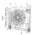
- FIG. 2 is a sectional view along line 2-2 in FIG. 1
- FIG. 3 is an enlarged view of part 3 in FIG. 1
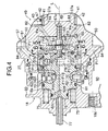
- FIG. 4 is an enlarged sectional view of part 4 in FIG. 1 (sectional view along line 4-4 in FIG. 8);
- FIG. 5 is a view from arrowed line 5-5 in FIG. 4;
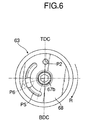
- FIG. 6 is a view from arrowed line 6-6 in FIG. 4;
- FIG. 7 is a sectional view along line 7-7 in FIG. 4;
- FIG. 8 is a sectional view along line 8-8 in FIG. 4;
- FIG. 9 is a sectional view along line 9-9 in FIG. 4;
- FIG. 1 is a vertical sectional view of an expander
- FIG. 2 is a sectional view along line 2-2 in FIG. 1
- FIG. 3 is an enlarged view of part 3 in FIG. 1
- FIG. 10 is a view from arrowed line 10-10 in FIG. 1;
- FIG. 11 is a view from arrowed line 11-11 in FIG. 1;
- FIG. 12 is a sectional view along line 12-12 in FIG. 10;
- FIG. 13 is a sectional view along line 13-13 in FIG. 11;
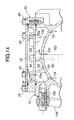
- FIG. 14 is a sectional view along line 14-14 in FIG. 10;
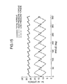
- FIG. 15 is a graph showing torque variations of an output shaft;
- FIG. 16 is an explanatory diagram showing the operation of an intake system of a high-pressure stage;
- FIG. 17 is an explanatory diagram showing the operation of a discharge system of the high-pressure stage and an intake system of a low-pressure stage; and
- FIG. 16 is an explanatory diagram showing the operation of an intake system of a high-pressure stage;
- FIG. 17 is an explanatory diagram showing the operation of a discharge system of the high-pressure stage and an intake system of a low-pressure stage; and
- FIG. 16 is an
- FIG. 18 is an explanatory diagram showing the operation of a discharge system of the low-pressure stage;
- FIG. 19 is a diagram showing the overall arrangement of the Rankine cycle system;
- FIG. 20 is a diagram showing the structure of water separating means;
- FIG. 21 is a sectional view along line 21-21 in FIG. 20;
- FIG. 22 is a sectional view along line 22-22 in FIG. 20;
- FIGS. 23A and 23B are diagrams showing the operation of a coalescer type filter for separating water;
- FIGS. 24A and 24B are diagrams showing the operation of a coalescer type filter for separating oil;
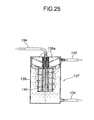
- FIG. 25 is a diagram showing the structure of oil separating means.
- the expander 113 converts the thermal energy and the pressure energy of high-temperature, high-pressure steam as a working medium into mechanical energy and outputs it.
- a casing 11 of the expander 113 is formed from a casing main body 12, a front cover 15 fitted via a seal 13 into a front opening of the casing main body 12 and joined thereto via a plurality of bolts 14, and a rear cover 18 fitted via a seal 16 onto a rear opening of the casing main body 12 and joined thereto via a plurality of bolts 17.
- An oil pan 19 abuts against a lower opening of the casing main body 12 via a seal 20 and is joined thereto via a plurality of bolts 21.
- a rotor 27 and an output shaft 28 that can rotate around an axis L extending in the fore-and-aft direction in the center of the casing 11 are united by welding.
- a rear part of the rotor 27 is rotatably supported in the casing main body 12 via an angular ball bearing 29 and a seal 30, and a front part of the output shaft 28 is rotatably supported in the front cover 15 via an angular ball bearing 31 and a seal 32.
- a swash plate holder 36 is fitted via two seals 33 and 34 and a knock pin 35 in a rear face of the front cover 15 and fixed thereto via a plurality of bolts 37, and a swash plate 39 is rotatably supported in the swash plate holder 36 via an angular ball bearing 38.
- the rotational axis of the swash plate 39 is inclined relative to the axis L of the rotor 27 and the output shaft 28, and the angle of inclination is fixed.
- Seven sleeves 41 formed from members that are separate from the rotor 27 are arranged within the rotor 27 so as to surround the axis L at equal intervals in the circumferential direction.
- High-pressure pistons 43 are slidably fitted in high-pressure cylinders 42 formed at inner peripheries of the sleeves 41, which are supported by sleeve support bores 27a of the rotor 27.
- Hemispherical parts of the high-pressure pistons 43 projecting forward from forward end openings of the high-pressure cylinders 42 abut against seven dimples 39a recessed in a rear surface of the swash plate 39.
- Heat resistant metal seals 44 are fitted between the rear ends of the sleeves 41 and the sleeve support bores 27a of the rotor 27, and a single set plate 45 retaining the front ends of the sleeves 41 in this state is fixed to a front surface of the rotor 27 by means of a plurality of bolts 46.
- the sleeve support bores 27a have a slightly larger diameter in the vicinity of their bases, thus forming a gap ⁇ (see FIG. 3) between themselves and the outer peripheries of the sleeves 41.
- the high-pressure pistons 43 include pressure rings 47 and oil rings 48 for sealing the surfaces that slide against the high-pressure cylinders 42, and the sliding range of the pressure rings 47 and the sliding range of the oil rings 48 are set so as not to overlap each other. Tapered openings 45a widening toward the front are formed in the set plate 45 in order to make the pressure rings 47 and the oil rings 48 engage smoothly with the high-pressure cylinders 42 when the high-pressure pistons 43 are inserted into the high-pressure cylinders 42.
- the sliding range of the pressure rings 47 and the sliding range of the oil rings 48 are set so as not to overlap each other, a lubricating medium oil attached to the inner walls of the high-pressure cylinders 42 against which the oil rings 48 slide will not be taken into high-pressure operating chambers 82 due to sliding of the pressure rings 47, thereby reliably preventing the oil from contaminating the steam.
- the high-pressure pistons 43 have a slightly smaller diameter part between the pressure rings 47 and the oil rings 48 (see FIG. 3), thereby effectively preventing the oil attached to the sliding surfaces of the oil rings 48 from moving to the sliding surfaces of the pressure rings 47.
- the high-pressure cylinders 42 are formed by fitting the seven sleeves 41 in the sleeve support bores 27a of the rotor 27, a material having excellent thermal conductivity, heat resistance, abrasion resistance, strength, etc. can be selected for the sleeves 41. This not only improves the performance and the reliability, but also machining becomes easy compared with a case in which the high-pressure cylinders 42 are directly machined in the rotor 27, and the machining precision also increases. When any one of the sleeves 41 is worn or damaged, it is possible to replace only the faulty sleeve 41, without replacing the entire rotor 27, and this is economical.
- the gap ⁇ is formed between the outer periphery of the sleeves 41 and the rotor 27 by slightly enlarging the diameter of the sleeve support bores 27a in the vicinity of the base, even when the rotor 27 is thermally deformed by the high-temperature, high-pressure steam supplied to the high-pressure operating chambers 82, this is prevented from affecting the sleeves 41, thereby preventing the high-pressure cylinders 42 from distorting.
- the seven high-pressure cylinders 42 and the seven high-pressure pistons 43 fitted therein form a first axial piston cylinder group 49.
- the seven low-pressure cylinders 50 and the seven low-pressure pistons 41 fitted therein form a second axial piston cylinder group 57.
- An oil used in a reciprocating engine, etc. contains a surfactant and an extreme pressure agent.
- Representative examples of the extreme pressure agent include molybdenum compounds represented by molybdenum sulfides (e.g., molybdenum disulfide, etc.).
- molybdenum compounds represented by molybdenum sulfides (e.g., molybdenum disulfide, etc.).
- the oil (hydrophilic oil) to which an extreme pressure agent has been added is strongly agitated, water is surrounded by the extreme pressure agent and the surfactant, which have hydrophilic groups, and not only is the function as a lubricating oil degraded, but also it becomes difficult to carry out separation of water since the emulsified mixture is stabilized. Because of this, in this embodiment a hydrophobic oil containing no hydrophilic additive is used as the lubricating medium of the expander 113.
- the rotor 27 and the output shaft 28, which are united, are supported respectively by the angular ball bearing 29 provided on the casing main body 12 and the angular ball bearing 31 provided on the front cover 15, by adjusting the thickness of a shim 58 disposed between the casing main body 12 and the angular ball bearing 29 and the thickness of a shim 59 disposed between the front cover 15 and the angular ball bearing 31, the longitudinal position of the rotor 27 along the axis L can be adjusted.
- the relative positional relationship in the axis L direction between the high-pressure and low-pressure pistons 43 and 51 guided by the swash plate 39, and the high-pressure and low-pressure cylinders 42 and 50 provided in the rotor 27 can be changed, thereby adjusting the expansion ratio of the steam in the high-pressure and low-pressure operating chambers 82 and 84.
- a high-pressure stage steam intake route for supplying high-temperature, high-pressure steam to the first axial piston cylinder group 49 is shown in FIG. 16 by a mesh pattern.
- a first steam passage P1 having its upstream end communicating with the pressure chamber 76, to which the high-temperature, high-pressure steam is supplied from the steam supply pipe 77, runs through the rotary valve main body 62, opens on the surface at which the rotary valve main body 62 is joined to the stationary valve plate 63, and communicates with a second steam passage P2 running through the stationary valve plate 63.
- Seven third steam passages P3 (see FIG. 5) and seven fourth steam passages P4 are formed respectively in the movable valve plate 64 and the rotor 27 at circumferentially equal intervals, and the downstream ends of the fourth steam passages P4 communicate with the seven high-pressure operating chambers 82 defined between the high-pressure cylinders 42 and the high-pressure pistons 43 of the first axial piston cylinder group 49.
- an opening of the second steam passage P2 formed in the stationary valve plate 63 does not open evenly to the front and rear of the top dead center (TDC) of the high-pressure pistons 43, but opens displaced slightly forward in the direction of rotation of the rotor 27, which is shown by the arrow R.
- first breather passage B1 formed in the breather chamber dividing wall 23 opens at mid height in the upper breather chamber 103.
- the other end of the first breather passage B1 communicates with the steam discharge chamber 90 via a second breather passage B2 formed in the casing main body 12 and a third breather passage B3 formed in the rear cover 18.
- the recess 12g which is formed in the upper wall 12a, communicates with the steam discharge chamber 90 via a fourth breather passage B4 formed in the casing main body 12 and the third breather passage B3.
- the outer periphery of a part providing communication between the first breather passage B1 and the second breather passage B2 is sealed by a seal 105.
- the oil accumulated in the oil pan 19 is stirred and splashed by the rotor 27 rotating within the lubrication chamber 102 of the casing 11, thereby lubricating sliding sections between the high-pressure cylinders 42 and the high-pressure pistons 43, sliding sections between the low-pressure cylinders 50 and the low-pressure pistons 51, the angular ball bearing 31 supporting the output shaft 28, the angular ball bearing 29 supporting the rotor 27, the angular ball bearing 38 supporting the swash plate 39, sliding sections between the high-pressure pistons 43 and the swash plate 39, the spherical bearings 54 and 56 at opposite ends of the links 52, etc.
- the interior of the lubrication chamber 102 is filled with oil mist generated by splashing due to stirring of the oil and oil vapor generated by vaporization due to heating by a high-temperature section of the rotor 27, and this is mixed with steam leaking into the lubrication chamber 102 from the high-pressure operating chambers 82 and low-pressure operating chambers 84.
- the pressure of the lubrication chamber 102 becomes higher than the pressure of the steam discharge chamber 90 due to the leakage of steam, the mixture of oil content and steam flows through the through hole 12b formed in the upper wall 12a of the casing main body 12 into the lower breather chamber 101.
- the water separating means 118 is provided with a coalescer type upstream side water separating device 121 and a coalescer type downstream side water separating device 122 in line.
- the upstream side water separating device 121 is for separating water from an oil-water mixture in which the oil supplied from the expander 113 is mixed with a small amount of water; a hydrophobic ultrafine nylon fiber cylindrical filter element 124 is disposed within a casing 123, and the oil-water mixture is supplied into the interior of the filter element 124.
- Control of the opening and closing of the upstream side switch valve 127 and the downstream side switch valve 128 can be carried out on the basis of the oil content of the water that is collected in, for example, the upstream side water separating device 121 and the downstream side water separating device 122. More specifically, since water is electrically conductive and oil is electrically nonconductive, as the oil content of the water increases, the electrical resistance increases, and the oil content can be detected based on this.
- the oil separating means 137 when the water-oil mixture passes through the filter element 140 from the inside to the outside, the small amount of oil contained in the water is captured by the ultrafine nylon fiber and gradually increases its size, and when it turns into oil droplets having a diameter of on the order of 2 to 3 mm, the oil droplets alone float upward due to the difference in specific gravity between the oil and water, which is lighter than oil, thus being separated from the water, which goes downward. In order to prevent the oil that has been collected at the top of the casing 139 of the oil separating means 137 from mixing again with the water due to vibration, etc.
- the internal combustion engine 111 is illustrated as the heat engine, but the present invention can also be applied to a Rankine cycle system employing a heat engine other than the internal combustion engine 111.
- the water separating means 118 comprises the upstream side water separating device 121 and the downstream side water separating device 122, but three or more water separating devices may be provided.
- the present invention can be appropriately applied to a Rankine cycle system utilizing waste heat of an internal combustion engine of an automobile, but it can also be applied to a Rankine cycle system utilizing waste heat of an internal combustion engine other than one of an automobile, or a heat engine other than an internal combustion engine.
Landscapes
- Engineering & Computer Science (AREA)
- Mechanical Engineering (AREA)
- General Engineering & Computer Science (AREA)
- Chemical & Material Sciences (AREA)
- Combustion & Propulsion (AREA)
- Engine Equipment That Uses Special Cycles (AREA)
- Hydraulic Motors (AREA)
Abstract
A Rankine cycle device provided with a working medium circulating circuit (110) including an evaporator (112), an expander (113), a condenser (114), and a pressure pump (115), wherein a mixture of oil for lubricating the expander and water, which is a working medium mixed therein, is fed to a coalescer type water separating means (118) to separate water from oil. The oil separated from the water in the water separating means is returned to the expander, while the water separated from the oil is returned to a working medium circulation circuit. This eliminates the need to supply water to the working medium circulation circuit and the need to supply oil to the expander.
Description
The present invention relates to a Rankine cycle system having an
evaporator, an expander, a condenser, and a feed pump provided along a
working medium circulation circuit and, in particular, to a Rankine cycle system
provided with means for separating a working medium that has become mixed
with a lubricating medium of the expander, or to a Rankine cycle system
provided with means for separating the lubricating medium of the expander that
has become mixed with the working medium.
When a lubricating medium of an expander has become mixed with a
working medium circulating around a closed circuit of a Rankine cycle system,
the amount of lubricating medium in the expander becomes insufficient, thus
degrading the efficiency of the expander or causing seizing. Japanese Utility
Model Publication No. 61-8170 discloses a gas/liquid separator for separating a
lubricating medium from a working medium and returning it to an expander.
There is also known from Japanese Patent Application Laid-open No.
63-156508 a so-called coalescer type oil/water separating filter in which, by
supplying a mixture of oil and water to an ultrafine fiber filter, oil droplets
attached to the fiber become coarser and thus separate from the water by
virtue of the difference in specific gravity between the oil and water, or water
droplets attached to the fiber become coarser and thus separate from the oil by
virtue of the difference in specific gravity between water and the oil.
However, in the Rankine cycle system disclosed in Japanese Utility
Model Publication No. 61-8170, since the mixture of the working medium and
the lubricating medium circulates in the closed circuit, there is a possibility that
the lubricating medium in the working medium circulating in the closed circuit
might gasify due to heat, thus affecting the performance and the durability of
the Rankine cycle system. Furthermore, since a mixture of liquid-phase
working medium, gas-phase working medium, and lubricating medium is
supplied from a boiler to the gas/liquid separator and, moreover, the gas/liquid
separator has a structure in which the lubricating medium is separated by
gravity, there is the problem that it is impossible to prevent the liquid-phase
working medium from becoming mixed with the lubricating medium.
The present invention has been achieved under the above-mentioned
circumstances, and it is an object thereof to provide a Rankine cycle system
equipped with an expander that is lubricated by a lubricating medium, the
lubricating medium of the expander being regenerated by reliably separating a
working medium that has become mixed with the lubricating medium, or the
working medium being regenerated by reliably separating the lubricating
medium that has become mixed with the working medium in the expander.
In order to achieve this object, in accordance with a first aspect of the
present invention, there is proposed a Rankine cycle system that includes a
working medium circulation circuit that includes an evaporator that generates a
high-temperature, high-pressure gas-phase working medium by heating a
liquid-phase working medium by means of waste heat of a heat engine, an
expander that converts the heat and pressure of the gas-phase working
medium supplied from the evaporator into mechanical energy, a condenser that
cools the gas-phase working medium whose temperature and pressure have
decreased in the expander to turn the working medium back into the liquid-phase
working medium, and a feed pump that supplies the liquid-phase working
medium discharged from the condenser to the evaporator, characterized in that
the expander has a sliding section thereof lubricated by a lubricating medium
that is different from the working medium, the Rankine cycle system further
includes working medium separating means for separating from the lubricating
medium the working medium that has become mixed with the lubricating
medium in the expander, and the working medium separating means is
provided at a position where the working medium is in a liquid-phase state.
In accordance with this arrangement, when separating the working
medium contained in the lubricating medium of the expander of the Rankine
cycle system, the lubricating medium is separated when the working medium is
in the liquid-phase state, and it is therefore possible to separate the lubricating
medium from the working medium more completely than can be done in a case
in which the liquid-phase working medium and the gas-phase working medium
are mixed.
Furthermore, in accordance with a second aspect of the present
invention, in addition to the first aspect, there is proposed a Rankine cycle
system wherein the working medium separating means exhibits a function of
separating the working medium in a predetermined temperature range, and the
working medium separating means is provided at a position where the
lubricating medium is in the predetermined temperature range.
In accordance with this arrangement, since the working medium
separating means that exhibits the function of separating the working medium
in the predetermined temperature range is provided at a position where the
temperature of the lubricating medium is in the predetermined temperature
range, the function of separating the working medium can be exhibited stably
while preventing any damage to the working medium separating means.
Moreover, in accordance with a third aspect of the present invention, in
addition to the first or second aspect, there is proposed a Rankine cycle system
wherein the working medium separating means is formed by connecting at least
two working medium separating devices in line.
In accordance with this arrangement, since the working medium
separating means is formed by connecting in line at least two working medium
separating devices, it is possible to vary the separation characteristics of each
of the working medium separating devices, and the separation performance can
be improved and the dimensions of the working medium separating means can
be reduced compared with a case in which the working medium separating
means is formed from one working medium separating device.
Furthermore, in accordance with a fourth aspect of the present invention,
there is proposed a Rankine cycle system that includes a working medium
circulation circuit that includes an evaporator that generates a high-temperature,
high-pressure gas-phase working medium by heating a liquid-phase
working medium by means of waste heat of a heat engine, an expander
that converts the heat and pressure of the gas-phase working medium supplied
from the evaporator into mechanical energy, a condenser that cools the gas-phase
working medium whose temperature and pressure have decreased in
the expander to turn the working medium back into the liquid-phase working
medium, and a feed pump that supplies the liquid-phase working medium
discharged from the condenser to the evaporator, characterized in that the
expander has a sliding section thereof lubricated by a lubricating medium that is
different from the working medium, the Rankine cycle system further includes
lubricating medium separating means for separating from the working medium
the lubricating medium that has become mixed with the working medium in the
expander, and the lubricating medium separating means is provided at a
position on the downstream side of the expander where the working medium is
in a liquid-phase state.
In accordance with this arrangement, when separating the lubricating
medium contained in the working medium of the Rankine cycle system, the
lubricating medium is separated when the working medium is in a liquid-phase
state, and it is therefore possible to separate the lubricating medium from the
working medium more completely than can be done in a case in which both the
liquid-phase working medium and the gas-phase working medium are mixed.
Moreover, in accordance with a fifth aspect of the present invention, in
addition to the fourth aspect, there is proposed a Rankine cycle system wherein
the lubricating medium separating means exhibits a function of separating the
lubricating medium in a predetermined temperature range, and the lubricating
medium separating means is provided at a position where the liquid-phase
working medium is in the predetermined temperature range.
In accordance with this arrangement, since the lubricating medium
separating means that exhibits the function of separating the lubricating
medium in the predetermined temperature range is provided at a position where
the temperature of the liquid-phase working medium is in the predetermined
temperature range, the function of separating the lubricating medium can be
exhibited stably while preventing any damage to the lubricating medium
separating means.
Furthermore, in accordance with a sixth aspect of the present invention,
in addition to the fourth or fifth aspect, there is proposed a Rankine cycle
system that further includes a gas/liquid separator for separating a liquid phase
portion contained in the working medium discharged from the expander into the
working medium circulation circuit, the liquid-phase working medium separated
by the gas/liquid separator being supplied to the lubricating medium separating
means.
In accordance with this arrangement, since the liquid phase portion
contained in the working medium discharged from the expander into the
working medium circulation circuit is separated by the gas/liquid separator and
supplied to the lubricating medium separating means, the working medium that
is to be supplied to the lubricating medium separating means is reliably
converted into the liquid phase, thereby improving the function of separating the
lubricating medium.
Moreover, in accordance with a seventh aspect of the present invention,
in addition to the first, second, fourth, or fifth aspect, there is proposed a
Rankine cycle system that further includes working medium purifying means for
removing cations or dissolved gas contained in the working medium that has
been discharged from the expander into the working medium circulation circuit
and that has been turned back into the liquid phase state.
In accordance with this arrangement, since the working medium purifying
means removes cations and dissolved gas contained in the working medium
that has been discharged from the expander into the working medium
circulation circuit and that has been turned back into the liquid-phase state,
contamination and corrosion of each section of the working medium circulation
circuit, through which the working medium circulates, can be prevented more
reliably.
Furthermore, in accordance with an eighth aspect of the present
invention, in addition to the first, second, fourth, or fifth aspect, there is
proposed a Rankine cycle system wherein the lubricating medium from which
the working medium has been separated by the working medium separating
means is returned to the expander.
In accordance with this arrangement, since the lubricating medium from
which the working medium has been separated by the working medium
separating means is returned to the expander, it is possible to prevent the
working medium from becoming mixed with the lubricating medium and
degrading the lubrication performance and, moreover, it is unnecessary to
replenish the expander with the lubricating medium.
Moreover, in accordance with a ninth aspect of the present invention, in
addition to the first, second, fourth, or fifth aspect, there is proposed a Rankine
cycle system wherein the working medium separated from the lubricating
medium by the working medium separating means is returned to the working
medium circulation circuit.
In accordance with this arrangement, since the working medium from
which the lubricating medium has been separated by the working medium
separating means is returned to the working medium circulation circuit, it is
possible to prevent any damage to the working medium circulation circuit due to
the lubricating medium becoming mixed with the working medium and,
moreover, it is unnecessary to replenish the working medium circulation circuit
with the working medium.
Furthermore, in accordance with a tenth aspect of the present invention,
in addition to the first, second, fourth, or fifth aspect, there is proposed a
Rankine cycle system wherein the working medium separating means makes
droplets of the working medium contained in the lubricating medium become
coarse, and the working medium is separated by virtue of a difference in
specific gravity between the lubricating medium and the working medium that
has been made into coarse droplets.
In accordance with this arrangement, since the working medium
separating means makes the droplets of the working medium become coarse
and separates them from the lubricating medium by virtue of the difference in
specific gravity, the working medium can be separated effectively from the
lubricating medium with small pressure loss.
Moreover, in accordance with an eleventh aspect of the present
invention, in addition to the first, second, fourth, or fifth aspect, there is
proposed a Rankine cycle system wherein the working medium separating
means is of a coalescer type.
In accordance with this arrangement, since the working medium
separating means is of the coalescer type, the working medium can be
separated effectively from the lubricating medium with small pressure loss.
Furthermore, in accordance with a twelfth aspect of the present
invention, in addition to the eleventh aspect, there is proposed a Rankine cycle
system wherein the working medium separating means includes a filter element
formed from hydrophobic fiber.
In accordance with this arrangement, since the filter element of the
working medium separating means is made of the hydrophobic fiber, the ability
to separate the working medium from the lubricating medium can be improved.
Moreover, in accordance with a thirteenth aspect of the present
invention, there is proposed a Rankine cycle system that includes a working
medium circulation circuit that includes an evaporator that generates a high-temperature,
high-pressure gas-phase working medium by heating a liquid-phase
working medium by means of waste heat of a heat engine, an expander
that converts the heat and pressure of the gas-phase working medium supplied
from the evaporator into mechanical energy, a condenser that cools the gas-phase
working medium whose temperature and pressure have decreased in
the expander to turn the working medium back into the liquid-phase working
medium, and a feed pump that supplies the liquid-phase working medium
discharged from the condenser to the evaporator, characterized in that the
expander has a sliding section thereof lubricated by a lubricating medium that is
different from the working medium, the Rankine cycle system further includes
working medium separating means for separating from the lubricating medium
the working medium that has become mixed with the lubricating medium in the
expander, and the lubricating medium is a hydrophobic oil containing no
extreme pressure additive having surface activity.
In accordance with this arrangement, when separating the working
medium contained in the lubricating medium of the expander by the working
medium separating means, since the lubricating medium is a hydrophobic oil
containing no extreme pressure additive having surface activity, it is possible to
prevent any degradation in the lubrication performance due to emulsification of
the lubricating medium and, moreover, the ability to separate the working
medium and the lubricating medium can be improved.
Water and steam of an embodiment correspond to the working medium
of the present invention, an oil of the embodiment corresponds to the
lubricating medium of the present invention, an internal combustion engine 111
of the embodiment corresponds to the heat engine of the present invention,
water separating means 118 of the embodiment corresponds to the working
medium separating means of the present invention, an upstream side water
separating device 121 and a downstream side water separating device 122 of
the embodiment correspond to the working medium separating device of the
present invention, water purifying means 132 of the embodiment corresponds
to the working medium purifying means of the present invention, and oil
separating means 137 of the embodiment corresponds to the lubricating
medium separating means of the present invention.
FIG. 1 to FIG. 25 illustrate one embodiment of the present invention;
FIG. 1 is a vertical sectional view of an expander; FIG. 2 is a sectional view
along line 2-2 in FIG. 1; FIG. 3 is an enlarged view of part 3 in FIG. 1; FIG. 4 is
an enlarged sectional view of part 4 in FIG. 1 (sectional view along line 4-4 in
FIG. 8); FIG. 5 is a view from arrowed line 5-5 in FIG. 4; FIG. 6 is a view from
arrowed line 6-6 in FIG. 4; FIG. 7 is a sectional view along line 7-7 in FIG. 4;
FIG. 8 is a sectional view along line 8-8 in FIG. 4; FIG. 9 is a sectional view
along line 9-9 in FIG. 4; FIG. 10 is a view from arrowed line 10-10 in FIG. 1;
FIG. 11 is a view from arrowed line 11-11 in FIG. 1; FIG. 12 is a sectional view
along line 12-12 in FIG. 10; FIG. 13 is a sectional view along line 13-13 in FIG.
11; FIG. 14 is a sectional view along line 14-14 in FIG. 10; FIG. 15 is a graph
showing torque variations of an output shaft; FIG. 16 is an explanatory diagram
showing the operation of an intake system of a high-pressure stage; FIG. 17 is
an explanatory diagram showing the operation of a discharge system of the
high-pressure stage and an intake system of a low-pressure stage; and FIG. 18
is an explanatory diagram showing the operation of a discharge system of the
low-pressure stage; FIG. 19 is a diagram showing the overall arrangement of
the Rankine cycle system; FIG. 20 is a diagram showing the structure of water
separating means; FIG. 21 is a sectional view along line 21-21 in FIG. 20; FIG.
22 is a sectional view along line 22-22 in FIG. 20; FIGS. 23A and 23B are
diagrams showing the operation of a coalescer type filter for separating water;
FIGS. 24A and 24B are diagrams showing the operation of a coalescer type
filter for separating oil; and FIG. 25 is a diagram showing the structure of oil
separating means.
An embodiment of the present invention is explained below with
reference to the attached drawings.
Firstly, an outline of the structure of an expander 113 of a Rankine cycle
system is explained with reference to FIG. 1 to FIG. 3.
The expander 113 converts the thermal energy and the pressure energy
of high-temperature, high-pressure steam as a working medium into
mechanical energy and outputs it. A casing 11 of the expander 113 is formed
from a casing main body 12, a front cover 15 fitted via a seal 13 into a front
opening of the casing main body 12 and joined thereto via a plurality of bolts
14, and a rear cover 18 fitted via a seal 16 onto a rear opening of the casing
main body 12 and joined thereto via a plurality of bolts 17. An oil pan 19 abuts
against a lower opening of the casing main body 12 via a seal 20 and is joined
thereto via a plurality of bolts 21. Furthermore, a breather chamber dividing
wall 23 is superimposed on an upper surface of the casing main body 12 via a
seal 22 (see FIG. 12), a breather chamber cover 25 is further superimposed on
an upper surface of the breather chamber dividing wall 23 via a seal 24 (see
FIG. 12), and they are together secured to the casing main body 12 by means
of a plurality of bolts 26.
A rotor 27 and an output shaft 28 that can rotate around an axis L
extending in the fore-and-aft direction in the center of the casing 11 are united
by welding. A rear part of the rotor 27 is rotatably supported in the casing main
body 12 via an angular ball bearing 29 and a seal 30, and a front part of the
output shaft 28 is rotatably supported in the front cover 15 via an angular ball
bearing 31 and a seal 32. A swash plate holder 36 is fitted via two seals 33 and
34 and a knock pin 35 in a rear face of the front cover 15 and fixed thereto via a
plurality of bolts 37, and a swash plate 39 is rotatably supported in the swash
plate holder 36 via an angular ball bearing 38. The rotational axis of the swash
plate 39 is inclined relative to the axis L of the rotor 27 and the output shaft 28,
and the angle of inclination is fixed.
Seven sleeves 41 formed from members that are separate from the rotor
27 are arranged within the rotor 27 so as to surround the axis L at equal
intervals in the circumferential direction. High-pressure pistons 43 are slidably
fitted in high-pressure cylinders 42 formed at inner peripheries of the sleeves
41, which are supported by sleeve support bores 27a of the rotor 27.
Hemispherical parts of the high-pressure pistons 43 projecting forward from
forward end openings of the high-pressure cylinders 42 abut against seven
dimples 39a recessed in a rear surface of the swash plate 39. Heat resistant
metal seals 44 are fitted between the rear ends of the sleeves 41 and the
sleeve support bores 27a of the rotor 27, and a single set plate 45 retaining the
front ends of the sleeves 41 in this state is fixed to a front surface of the rotor
27 by means of a plurality of bolts 46. The sleeve support bores 27a have a
slightly larger diameter in the vicinity of their bases, thus forming a gap α (see
FIG. 3) between themselves and the outer peripheries of the sleeves 41.
The high-pressure pistons 43 include pressure rings 47 and oil rings 48
for sealing the surfaces that slide against the high-pressure cylinders 42, and
the sliding range of the pressure rings 47 and the sliding range of the oil rings
48 are set so as not to overlap each other. Tapered openings 45a widening
toward the front are formed in the set plate 45 in order to make the pressure
rings 47 and the oil rings 48 engage smoothly with the high-pressure cylinders
42 when the high-pressure pistons 43 are inserted into the high-pressure
cylinders 42.
As hereinbefore described, since the sliding range of the pressure rings
47 and the sliding range of the oil rings 48 are set so as not to overlap each
other, a lubricating medium oil attached to the inner walls of the high-pressure
cylinders 42 against which the oil rings 48 slide will not be taken into high-pressure
operating chambers 82 due to sliding of the pressure rings 47, thereby
reliably preventing the oil from contaminating the steam. In particular, the high-pressure
pistons 43 have a slightly smaller diameter part between the pressure
rings 47 and the oil rings 48 (see FIG. 3), thereby effectively preventing the oil
attached to the sliding surfaces of the oil rings 48 from moving to the sliding
surfaces of the pressure rings 47.
Since the high-pressure cylinders 42 are formed by fitting the seven
sleeves 41 in the sleeve support bores 27a of the rotor 27, a material having
excellent thermal conductivity, heat resistance, abrasion resistance, strength,
etc. can be selected for the sleeves 41. This not only improves the
performance and the reliability, but also machining becomes easy compared
with a case in which the high-pressure cylinders 42 are directly machined in the
rotor 27, and the machining precision also increases. When any one of the
sleeves 41 is worn or damaged, it is possible to replace only the faulty sleeve
41, without replacing the entire rotor 27, and this is economical.
Furthermore, since the gap α is formed between the outer periphery of
the sleeves 41 and the rotor 27 by slightly enlarging the diameter of the sleeve
support bores 27a in the vicinity of the base, even when the rotor 27 is
thermally deformed by the high-temperature, high-pressure steam supplied to
the high-pressure operating chambers 82, this is prevented from affecting the
sleeves 41, thereby preventing the high-pressure cylinders 42 from distorting.
The seven high-pressure cylinders 42 and the seven high-pressure
pistons 43 fitted therein form a first axial piston cylinder group 49.
Seven low-pressure cylinders 50 are arranged at circumferentially equal
intervals on the outer peripheral part of the rotor 27 so as to surround the axis L
and the radially outer side of the high-pressure cylinders 42. These low-pressure
cylinders 50 have a larger diameter than that of the high-pressure
cylinders 42, and the pitch at which the low-pressure cylinders 50 are arranged
in the circumferential direction is displaced by half a pitch relative to the pitch at
which the high-pressure cylinders 42 are arranged in the circumferential
direction. This makes it possible for the high-pressure cylinders 42 to be
arranged in spaces formed between adjacent low-pressure cylinders 50, thus
utilizing the spaces effectively and contributing to a reduction in the diameter of
the rotor 27.
The seven low-pressure cylinders 50 have low-pressure pistons 51
slidably fitted thereinto, and these low-pressure pistons 51 are connected to the
swash plate 39 via links 52. That is, spherical parts 52a at the front end of the
links 52 are swingably supported in spherical bearings 54 fixed to the swash
plate 39 via nuts 53, and spherical parts 52b at the rear end of the links 52 are
swingably supported in spherical bearings 56 fixed to the low-pressure pistons
51 by clips 55. A pressure ring 78 and an oil ring 79 are fitted around the outer
periphery of each of the low-pressure pistons 51 in the vicinity of the top
surface thereof so as to adjoin each other. Since the sliding ranges of the
pressure ring 78 and the oil ring 79 overlap each other, an oil film is formed on
the sliding surface of the pressure ring 78, thus enhancing the sealing
characteristics and the lubrication.
The seven low-pressure cylinders 50 and the seven low-pressure pistons
41 fitted therein form a second axial piston cylinder group 57.
An oil used in a reciprocating engine, etc. contains a surfactant and an
extreme pressure agent. Representative examples of the extreme pressure
agent include molybdenum compounds represented by molybdenum sulfides
(e.g., molybdenum disulfide, etc.). When the oil (hydrophilic oil) to which an
extreme pressure agent has been added is strongly agitated, water is
surrounded by the extreme pressure agent and the surfactant, which have
hydrophilic groups, and not only is the function as a lubricating oil degraded, but
also it becomes difficult to carry out separation of water since the emulsified
mixture is stabilized. Because of this, in this embodiment a hydrophobic oil
containing no hydrophilic additive is used as the lubricating medium of the
expander 113.
As hereinbefore described, since the front ends of the high-pressure
pistons 43 of the first axial piston cylinder group 49 are made in the form of
hemispheres and are made to abut against the dimples 39a formed in the
swash plate 39, it is unnecessary to connect the high-pressure pistons 43 to the
swash plate 39 mechanically, thus reducing the number of parts and improving
the ease of assembly. On the other hand, the low-pressure pistons 51 of the
second axial piston cylinder group 57 are connected to the swash plate 39 via
the links 52 and their front and rear spherical bearings 54 and 56, and even
when the temperature and the pressure of medium-temperature, medium-pressure
steam supplied to the second axial piston cylinder group 57 become
insufficient and the pressure of low-pressure operating chambers 84 becomes
negative, there is no possibility of the low-pressure pistons 51 becoming
detached from the swash plate 39 and causing knocking or damage.
Furthermore, when the swash plate 39 is secured to the front cover 15
via the bolts 37, changing the phase at which the swash plate 39 is secured
around the axis L enables the timing of supply and discharge of the steam to
and from the first axial piston cylinder group 49 and the second axial piston
cylinder group 57 to be shifted, thereby altering the output characteristics of the
expander 113.
Moreover, since the rotor 27 and the output shaft 28, which are united,
are supported respectively by the angular ball bearing 29 provided on the
casing main body 12 and the angular ball bearing 31 provided on the front
cover 15, by adjusting the thickness of a shim 58 disposed between the casing
main body 12 and the angular ball bearing 29 and the thickness of a shim 59
disposed between the front cover 15 and the angular ball bearing 31, the
longitudinal position of the rotor 27 along the axis L can be adjusted. By
adjusting the position of the rotor 27 in the axis L direction, the relative
positional relationship in the axis L direction between the high-pressure and
low- pressure pistons 43 and 51 guided by the swash plate 39, and the high-pressure
and low- pressure cylinders 42 and 50 provided in the rotor 27 can be
changed, thereby adjusting the expansion ratio of the steam in the high-pressure
and low- pressure operating chambers 82 and 84.
If the swash plate holder 36 supporting the swash plate 39 were formed
integrally with the front cover 15, it would be difficult to secure a space for
attaching and detaching the angular ball bearing 31 or the shim 59 to and from
the front cover 15, but since the swash plate holder 36 is made detachable from
the front cover 15, the above-mentioned problem can be eliminated. Moreover,
if the swash plate holder 36 were integral with the front cover 15, during
assembly and disassembly of the expander 113 it would be necessary to carry
out cumbersome operations of connecting and disconnecting the seven links
52, which are in a confined space within the casing 11, to and from the swash
plate 39 pre-assembled to the front cover 15, but since the swash plate holder
36 is made detachable from the front cover 15, it becomes possible to form a
sub-assembly by assembling the swash plate 39 and the swash plate holder 36
to the rotor 27 in advance, thereby greatly improving the ease of assembly.
Systems for supply and discharge of steam to and from the first axial
piston cylinder group 49 and the second axial piston cylinder group 57 are now
explained with reference to FIG. 4 to FIG. 9.
As shown in FIG. 4, a rotary valve 61 is housed in a circular cross-section
recess 27b opening on the rear end surface of the rotor 27 and a
circular cross-section recess 18a opening on a front surface of the rear cover
18. The rotary valve 61, which is disposed along the axis L, includes a rotary
valve main body 62, a stationary valve plate 63, and a movable valve plate 64.
The movable valve plate 64 is fixed to the rotor 27 via a knock pin 66 and a bolt
67a in a state in which it is fitted to the base of the recess 27b of the rotor 27
via a gasket 65. The stationary valve plate 63, which abuts against the
movable valve plate 64 via a flat sliding surface 68, is joined via a knock pin 69
and a bolt 67b to the rotary valve main body 62 so that there is no relative
rotation therebetween. When the rotor 27 rotates, the movable valve plate 64
and the stationary valve plate 63 therefore rotate relative to each other on the
sliding surface 68 in a state in which they are in intimate contact with each
other. The stationary valve plate 63 and the movable valve plate 64 are made
of a material having excellent durability, such as a super hard alloy or a
ceramic, and the sliding surface 68 can be provided with or coated with a
member having heat resistance, lubricating properties, corrosion resistance, or
abrasion resistance.
The rotary valve main body 62 is a stepped cylindrical member having a
large diameter part 62a, a medium diameter part 62b, and a small diameter part
62c; an annular sliding member 70 fitted around the outer periphery of the large
diameter part 62a is slidably fitted in the recess 27b of the rotor 27 via a
cylindrical sliding surface 71, and the medium diameter part 62b and the small
diameter part 62c are fitted in the recess 18a of the rear cover 18 via seals 72
and 73. The sliding member 70 is made of a material having excellent
durability, such as a super hard alloy or a ceramic. A knock pin 74 implanted in
the outer periphery of the rotary valve main body 62 engages with a long hole
18b formed in the recess 18a of the rear cover 18 in the axis L direction, and
the rotary valve main body 62 is therefore supported so that it can move in the
axis L direction but cannot rotate relative to the rear cover 18.
A plurality of (for example, seven) preload springs 75 are supported in
the rear cover 18 so as to surround the axis L, and the rotary valve main body
62, which has a step 62d between the medium diameter part 62b and the small
diameter part 62c pressed by these preload springs 75, is biased forward so as
to make the sliding surface 68 of the stationary valve plate 63 and the movable
valve plate 64 come into intimate contact with each other. A pressure chamber
76 is defined between the bottom of the recess 18a of the rear cover 18 and the
rear end surface of the small diameter part 62c of the rotary valve main body
62, and a steam supply pipe 77 connected so as to run though the rear cover
18 communicates with the pressure chamber 76. The rotary valve main body
62 is therefore biased forward by the steam pressure acting on the pressure
chamber 76 in addition to the resilient force of the preload springs 75.
A high-pressure stage steam intake route for supplying high-temperature,
high-pressure steam to the first axial piston cylinder group 49 is
shown in FIG. 16 by a mesh pattern. As is clear from FIG. 16 together with
FIG. 5 to FIG. 9, a first steam passage P1 having its upstream end
communicating with the pressure chamber 76, to which the high-temperature,
high-pressure steam is supplied from the steam supply pipe 77, runs through
the rotary valve main body 62, opens on the surface at which the rotary valve
main body 62 is joined to the stationary valve plate 63, and communicates with
a second steam passage P2 running through the stationary valve plate 63. In
order to prevent the steam from leaking past the surface at which the rotary
valve main body 62 and the stationary valve plate 63 are joined, the joining
surface is equipped with a seal 81 (see FIG. 7 and FIG. 16), which seals the
outer periphery of a connecting part between the first and second steam
passages P1 and P2.
Seven third steam passages P3 (see FIG. 5) and seven fourth steam
passages P4 are formed respectively in the movable valve plate 64 and the
rotor 27 at circumferentially equal intervals, and the downstream ends of the
fourth steam passages P4 communicate with the seven high-pressure
operating chambers 82 defined between the high-pressure cylinders 42 and the
high-pressure pistons 43 of the first axial piston cylinder group 49. As is clear
from FIG. 6, an opening of the second steam passage P2 formed in the
stationary valve plate 63 does not open evenly to the front and rear of the top
dead center (TDC) of the high-pressure pistons 43, but opens displaced slightly
forward in the direction of rotation of the rotor 27, which is shown by the arrow
R. This enables as long an expansion period as possible, that is, a sufficient
expansion ratio, to be maintained, negative work, which would be generated if
the opening were set evenly to the front and rear of the TDC, to be minimized
and, moreover, the expanded steam remaining in the high-pressure operating
chambers 82 to be reduced, thus providing sufficient output (efficiency).
A high-pressure stage steam discharge route and a low-pressure stage
steam intake route for discharging medium-temperature, medium-pressure
steam from the first axial piston cylinder group 49 and supplying it to the second
axial piston cylinder group 57 are shown in FIG. 17 by a mesh pattern. As is
clear from FIG. 17 together with FIG. 5 to FIG. 8, an arc-shaped fifth steam
passage P5 (see FIG. 6) opens on a front surface of the stationary valve plate
63, and this fifth steam passage P5 communicates with a circular sixth steam
passage P6 (see FIG. 7) opening on a rear surface of the stationary valve plate
63. The fifth steam passage P5 opens from a position displaced slightly
forward in the direction of rotation of the rotor 27, which is shown by the arrow
R, relative to the bottom dead center (BDC) of the high-pressure pistons 43 to
a position displaced slightly backward in the rotational direction relative to the
TDC. This enables the third steam passages P3 of the movable valve plate 64
to communicate with the fifth steam passage P5 of the stationary valve plate 63
over an angular range that starts from the BDC and does not overlap the
second steam passage P2 (preferably, immediately before overlapping the
second steam passage P2), and in this range the steam is discharged from the
third steam passages P3 to the fifth steam passage P5.
Formed in the rotary valve main body 62 are a seventh steam passage
P7 extending in the axis L direction and an eighth steam passage P8 extending
in a substantially radial direction. The upstream end of the seventh steam
passage P7 communicates with the downstream end of the sixth steam
passage P6. The downstream end of the seventh steam passage P7
communicates with a tenth steam passage P10 running radially through the
sliding member 70 via a ninth steam passage P9 within a coupling member 83
disposed so as to bridge between the rotary valve main body 62 and the sliding
member 70. The tenth steam passage P10 communicates with the seven low-pressure
operating chambers 84 defined between the low-pressure cylinders 50
and the low-pressure pistons 41 of the second axial piston cylinder group 57 via
seven eleventh steam passages P11 formed radially in the rotor 27.
In order to prevent the steam from leaking past the joining surfaces of
the rotary valve main body 62 and the stationary valve plate 63, the outer
periphery of a part where the sixth and seventh steam passages P6 and P7 are
connected is sealed by equipping the joining surfaces with a seal 85 (see FIG.
7 and FIG. 17). Two seals 86 and 87 are disposed between the inner periphery
of the sliding member 70 and the rotary valve main body 62, and a seal 88 is
disposed between the outer periphery of the coupling member 83 and the
sliding member 70.
A steam discharge route for discharging low-temperature, low-pressure
steam from the second axial piston cylinder group 57 is shown in FIG. 18 by a
mesh pattern. As is clear from reference to FIG. 18 together with FIG. 8 and
FIG. 9, an arc-shaped sixteenth steam passage P16 that can communicate with
the seven eleventh steam passages P11 formed in the rotor 27 is cut out in the
sliding surface 71 of the sliding member 70. This sixteenth steam passage P16
communicates with a seventeenth steam passage P17 that is cut out in an arc-shape
in the outer periphery of the rotary valve main body 62. The sixteenth
steam passage P16 opens from a position displaced slightly forward in the
direction of rotation of the rotor 27, which is shown by the arrow R, relative to
the BDC of the low-pressure pistons 51 to a position displaced slightly
backward in the direction of rotation of the rotor 27 relative to the TDC. This
allows the eleventh steam passages P11 of the rotor 27 to communicate with
the sixteenth steam passage P16 of the sliding member 70 over an angular
range that starts from the BDC and does not overlap the tenth steam passage
P10 (preferably, immediately before overlapping the tenth steam passage
P10), and in this range the steam is discharged from the eleventh steam
passages P11 to the sixteenth steam passage P16.
The seventeenth steam passage P17 further communicates with a
steam discharge chamber 90 formed between the rotary valve main body 62
and the rear cover 18 via an eighteenth steam passage P18 to a twentieth
steam passage P20 formed within the rotary valve main body 62 and a cutout
18d of the rear cover 18, and this steam discharge chamber 90 communicates
with a steam discharge hole 18c formed in the rear cover 18.
As hereinbefore described, since the supply and discharge of the steam
to and from the first axial piston cylinder group 49 and the supply and discharge
of the steam to and from the second axial piston cylinder group 57 are
controlled by the common rotary valve 61, in comparison with a case in which
separate rotary valves are used for each, the dimensions of the expander 113
can be reduced. Moreover, since a valve for supplying the high-temperature,
high-pressure steam to the first axial piston cylinder group 49 is formed on the
flat sliding surface 68 on the front end of the stationary valve plate 63, which is
integral with the rotary valve main body 62, it is possible to prevent effectively
the high-temperature, high-pressure steam from leaking. This is because the
flat sliding surface 68 can be machined easily with high precision, and control of
clearance is easier than for a cylindrical sliding surface.
In particular, since the plurality of preload springs 75 apply a preset load
to the rotary valve main body 62 and bias it forward in the axis L direction, and
the high-temperature, high-pressure steam supplied from the steam supply pipe
77 to the pressure chamber 76 biases the rotary valve main body 62 forward in
the axis L direction, a surface pressure is generated on the sliding surface 68
between the stationary valve plate 63 and the movable valve plate 64 in
response to the pressure of the high-temperature, high-pressure steam, and it
is thus possible to prevent yet more effectively the steam from leaking past the
sliding surface 68.
Although a valve for supplying the medium-temperature, medium-pressure
steam to the second axial piston cylinder group 57 is formed on the
cylindrical sliding surface 71 on the outer periphery of the rotary valve main
body 62, since the pressure of the medium-temperature, medium-pressure
steam passing through the valve is lower than the pressure of the high-temperature,
high-pressure steam, leakage of the steam can be suppressed to
a practically acceptable level by maintaining a predetermined clearance even
without generating a surface pressure on the sliding surface 71.
Furthermore, since the first steam passage P1 through which the high-temperature,
high-pressure steam passes, the seventh steam passage P7 and
the eighth steam passage P8 through which the medium-temperature, medium-pressure
steam passes, and the seventeenth steam passage P17 to the
twentieth steam passage P20 through which the low-temperature, low-pressure
steam passes are collectively formed within the rotary valve main body 62, not
only can the steam temperature be prevented from dropping, but also the parts
(for example, the seal 81) sealing the high-temperature, high-pressure steam
can be cooled by the low-temperature, low-pressure steam, thus improving the
durability.
Moreover, since the rotary valve 61 can be attached to and detached
from the casing main body 12 merely by removing the rear cover 18 from the
casing main body 12, the ease of maintenance operations such as repair,
cleaning, and replacement can be greatly improved. Furthermore, although the
temperature of the rotary valve 61 through which the high-temperature, high-pressure
steam passes becomes high, since the swash plate 39 and the output
shaft 28, where lubrication by oil is required, are disposed on the opposite side
to the rotary valve 61 relative to the rotor 27, the oil is prevented from being
heated by the heat of the rotary valve 61 when it is at high temperature, which
would degrade the performance in lubricating the swash plate 39 and the output
shaft 28. Moreover, the oil can exhibit a function of cooling the rotary valve 61,
thus preventing overheating.
As is clear from FIG. 1, the oil that is stored in the oil pan 19 is returned
to the expander 113 via an oil passage 91, an oil pump 92 driven by the output
shaft 28, and an oil reservoir 89 formed within the output shaft 28, and during
this process water contained in the oil is separated. The details thereof will be
explained later.
The structure of a breather is now explained by reference to FIG. 10 to
FIG. 14.
A lower breather chamber 101 defined between an upper wall 12a of the
casing main body 12 and the breather chamber dividing wall 23 communicates
with a lubrication chamber 102 within the casing 11 via a through hole 12b
formed in the upper wall 12a of the casing main body 12. Oil is stored in the oil
pan 19 provided in a bottom part of the lubrication chamber 102, and the oil
level is slightly higher than the lower end of the rotor 27 (see FIG. 1). Provided
within the lower breather chamber 101 so as to project upward are three
dividing walls 12c to 12e having their upper ends in contact with a lower surface
of the breather chamber dividing wall 23. The through hole 12b opens at one
end of a labyrinth formed by these dividing walls 12c to 12e, and four oil return
holes 1 2f running through the upper wall 12a are formed partway along the
route to the other end of the labyrinth. The oil return holes 12f are formed at
the lowest position of the lower breather chamber 101 (see FIG. 14), and the
oil condensed within the lower breather chamber 101 can therefore be reliably
returned to the lubrication chamber 102.
An upper breather chamber 103 is defined between the breather
chamber dividing wall 23 and the breather chamber cover 25, and this upper
breather chamber 103 communicates with the lower breather chamber 101 via
four through holes 23a and 23b running through the breather chamber dividing
wall 23 and projecting chimney-like within the upper breather chamber 103. A
recess 12g is formed in the upper wall 12a of the casing main body 12 at a
position below a condensed water return hole 23c running through the breather
chamber dividing wall 23, and the periphery of the recess 12g is sealed by a
seal 104.
One end of a first breather passage B1 formed in the breather chamber
dividing wall 23 opens at mid height in the upper breather chamber 103. The
other end of the first breather passage B1 communicates with the steam
discharge chamber 90 via a second breather passage B2 formed in the casing
main body 12 and a third breather passage B3 formed in the rear cover 18.
Furthermore, the recess 12g, which is formed in the upper wall 12a,
communicates with the steam discharge chamber 90 via a fourth breather
passage B4 formed in the casing main body 12 and the third breather passage
B3. The outer periphery of a part providing communication between the first
breather passage B1 and the second breather passage B2 is sealed by a seal
105.
As shown in FIG. 2, a coupling 106 communicating with the lower
breather chamber 101 and a coupling 107 communicating with the oil pan 19
are connected together by a transparent oil level gauge 108, and the oil level
within the lubrication chamber 102 can be checked from the outside by the oil
level of this oil level gauge 108. That is, the lubrication chamber 102 has a
sealed structure, it is difficult to insert an oil level gauge from the outside from
the viewpoint of maintaining sealing characteristics, and the structure will
inevitably become complicated. However, this oil level gauge 108 enables the
oil level to be checked easily from the outside while maintaining the lubrication
chamber 102 in a sealed state.
The operation of the expander 113 having the above-mentioned
arrangement is now explained.
As shown in FIG. 16, high-temperature, high-pressure steam generated
by heating water in an evaporator is supplied to the pressure chamber 76 of the
expander 113 via the steam supply pipe 77, and reaches the sliding surface 68
with the movable valve plate 64 via the first steam passage P1 formed in the
rotary valve main body 62 of the rotary valve 61 and the second steam passage
P2 formed in the stationary valve plate 63 integral with the rotary valve main
body 62. The second steam passage P2 opening on the sliding surface 68
communicates momentarily with the third steam passage P3 formed in the
movable valve plate 64 rotating integrally with the rotor 27, and the high-temperature,
high-pressure steam is supplied, via the fourth steam passage P4
formed in the rotor 27, from the third steam passage P3 to, among the seven
high-pressure operating chambers 82 of the first axial piston cylinder group 49,
the high-pressure operating chamber 82 that is present at the top dead center.
Even after the communication between the second steam passage P2
and the third steam passage P3 has been blocked due to rotation of the rotor
27, the high-temperature, high-pressure steam expands within the high-pressure
operating chamber 82 and causes the high-pressure piston 43 fitted in
the high-pressure cylinder 42 of the sleeve 41 to be pushed forward from top
dead center toward bottom dead center, and the front end of the high-pressure
piston 43 presses against the dimple 39a of the swash plate 39. As a result,
the reaction force that the high-pressure pistons 43 receive from the swash
plate 39 gives a rotational torque to the rotor 27. For each one seventh of a
revolution of the rotor 27, the high-temperature, high-pressure steam is
supplied into a fresh high-pressure operating chamber 82, thus continuously
rotating the rotor 27.
As shown in FIG. 17, while the high-pressure piston 43, which has
reached bottom dead center, moves back toward top dead center
accompanying rotation of the rotor 27, the medium-temperature, medium-pressure
steam pushed out of the high-pressure operating chamber 82 is
supplied to the eleventh steam passage P11 communicating with the low-pressure
operating chamber 84 that, among the second axial piston cylinder
group 57, has reached top dead center accompanying rotation of the rotor 27,
via the fourth steam passage P4 of the rotor 27, the third steam passage P3 of
the movable valve plate 64, the sliding surface 68, the fifth steam passage P5
and the sixth steam passage P6 of the stationary valve plate 63, the seventh
steam passage P7 to the tenth steam passage P10 of the rotary valve main
body 62, and the sliding surface 71. Since the medium-temperature, medium-pressure
steam supplied to the low-pressure operating chamber 84 expands
within the low-pressure operating chambers 84 even after the communication
between the tenth steam passage P10 and the eleventh steam passage P11 is
blocked, the low-pressure piston 51 fitted in the low-pressure cylinder 50 is
pushed forward from top dead center toward bottom dead center, and the link
52 connected to the low-pressure piston 51 presses against the swash plate 39.
As a result, the pressure force of the low-pressure piston 51 is converted into a
rotational force of the swash plate 39 via the link 52, and this rotational force
transmits a rotational torque from the high-pressure piston 43 to the rotor 27 via
the dimple 39a of the swash plate 39. That is, the rotational torque is
transmitted to the rotor 27, which rotates synchronously with the swash plate
39. In order to prevent the low-pressure piston 51 from becoming detached
from the swash plate 39 when a negative pressure is generated during the
expansion stroke, the link 52 carries out a function of maintaining a connection
between the low-pressure piston 51 and the swash plate 39, and it is arranged
that the rotational torque due to the expansion is transmitted from the high-pressure
piston 43 to the rotor 27 rotating synchronously with the swash plate
39 via the dimples 39a of the swash plate 39 as described above. For each
one seventh of a revolution of the rotor 27, the medium-temperature, medium-pressure
steam is supplied into a fresh low-pressure operating chamber 84,
thus continuously rotating the rotor 27.
As shown in FIG. 18, while the low-pressure piston 51, which has
reached bottom dead center, moves back toward top dead center
accompanying rotation of the rotor 27, the low-temperature, low-pressure steam
pushed out of the low-pressure operating chamber 84 is discharged into the
steam discharge chamber 90 via the eleventh steam passage P11 of the rotor
27, the sliding surface 71, the sixteenth steam passage P16 of the sliding
member 70, and the seventeenth steam passage P17 to the twentieth steam
passage P20 of the rotary valve main body 62, and is supplied therefrom into a
condenser via the steam discharge hole 18c.
When the expander 113 operates as described above, since the seven
high-pressure pistons 43 of the first axial piston cylinder group 49 and the
seven low-pressure pistons 51 of the second axial piston cylinder group 57 are
connected to the common swash plate 39, the outputs of the first and second
axial piston cylinder groups 49 and 57 can be combined to drive the output
shaft 28, thereby achieving a high output while reducing the size of the
expander 113. During this process, since the seven high-pressure pistons 43
of the first axial piston cylinder group 49 and the seven high-pressure pistons
51 of the second axial piston cylinder group 57 are displaced by half a pitch in
the circumferential direction, as shown in FIG. 15, pulsations in the output
torque of the first axial piston cylinder group 49 and pulsations in the output
torque of the second axial piston cylinder group 57 balance each other out, thus
making the output torque of the output shaft 28 flat.
Furthermore, although axial type rotary fluid machines characteristically
have a higher space efficiency than radial type rotary fluid machines, by
arranging two stages in the radial direction the space efficiency can be further
enhanced. In particular, since the axial piston cylinders of the first group 49,
which are required to have only a small diameter because they are operated by
high-pressure steam having a small volume, are arranged on the radially inner
side, and the axial piston cylinders of the second group 57, which are required
to have a large diameter because they are operated by low-pressure steam
having a large volume, are arranged on the radially outer side, the space can
be utilized effectively, thus making the expander 113 still smaller. Moreover,
since the cylinders 42 and 50 and the pistons 43 and 51 that are used have
circular cross sections, which enables machining to be carried out with high
precision, the amount of steam leakage can be reduced in comparison with a
case in which vanes are used, and a yet higher output can thus be anticipated.
Furthermore, since the first axial piston cylinder group 49 operated by
high-temperature steam is arranged on the radially inner side, and the second
axial piston cylinder group 57 operated by low-temperature steam is arranged
on the radially outer side, the difference in temperature between the second
axial piston cylinder group 57 and the outside of the casing 11 can be
minimized, the amount of heat released outside the casing 11 can be
minimized, and the efficiency of the expander 113 can be enhanced.
Moreover, since the heat escaping from the high-temperature first axial piston
cylinder group 49 on the radially inner side can be recovered by the low-temperature
second axial piston cylinder group 57 on the radially outer side, the
efficiency of the expander 113 can be further enhanced.
Moreover, when viewed from an angle perpendicular to the axis L, since
the rear end of the first axial piston cylinder group 49 is positioned forward
relative to the rear end of the second axial piston cylinder group 57, heat
escaping rearward in the axis L direction from the first axial piston cylinder
group 49 can be recovered by the second axial piston cylinder group 57, and
the efficiency of the expander 113 can be yet further enhanced. Furthermore,
since the sliding surface 68 on the high-pressure side is present deeper within
the recess 27b of the rotor 27 than the sliding surface 71 on the low-pressure
side, the difference in pressure between the outside of the casing 11 and the
sliding surface 71 on the low-pressure side can be minimized, the amount of
steam leaking past the sliding surface 71 on the low-pressure side can be
reduced and, moreover, the pressure of steam leaking past the sliding surface
68 on the high-pressure side can be recovered by the sliding surface 71 on the
low-pressure side and utilized effectively.
During operation of the expander 113, the oil accumulated in the oil pan
19 is stirred and splashed by the rotor 27 rotating within the lubrication chamber
102 of the casing 11, thereby lubricating sliding sections between the high-pressure
cylinders 42 and the high-pressure pistons 43, sliding sections
between the low-pressure cylinders 50 and the low-pressure pistons 51, the
angular ball bearing 31 supporting the output shaft 28, the angular ball bearing
29 supporting the rotor 27, the angular ball bearing 38 supporting the swash
plate 39, sliding sections between the high-pressure pistons 43 and the swash
plate 39, the spherical bearings 54 and 56 at opposite ends of the links 52, etc.
The interior of the lubrication chamber 102 is filled with oil mist
generated by splashing due to stirring of the oil and oil vapor generated by
vaporization due to heating by a high-temperature section of the rotor 27, and
this is mixed with steam leaking into the lubrication chamber 102 from the high-pressure
operating chambers 82 and low-pressure operating chambers 84.
When the pressure of the lubrication chamber 102 becomes higher than the
pressure of the steam discharge chamber 90 due to the leakage of steam, the
mixture of oil content and steam flows through the through hole 12b formed in
the upper wall 12a of the casing main body 12 into the lower breather chamber
101. The interior of the lower breather chamber 101 has a labyrinth structure
due to the dividing walls 12c to 12e; the oil that condenses while passing
therethrough drops through the four oil return holes 12f formed in the upper wall
12a of the casing main body 12, and is returned to the lubrication chamber 102.
The steam from which the oil content has been removed passes through
the four through holes 23a and 23b of the breather chamber dividing wall 23,
flows into the upper breather chamber 103, and condenses by losing its heat to
the outside air via the breather chamber cover 25, which defines an upper wall
of the upper breather chamber 103. Water that has condensed within the
upper breather chamber 103 passes through the condensed water return hole
23c formed in the breather chamber dividing wall 23 and drops into the recess
12g without flowing into the four through holes 23a, 23b projecting chimney-like
within the upper breather chamber 103, and is discharged therefrom into the
steam discharge chamber 90 via the fourth breather passage B4 and the third
breather passage B3. Here, the amount of condensed water returned into the
steam discharge chamber 90 corresponds to the amount of steam that has
leaked from the high-pressure operating chambers 82 and the low-pressure
operating chambers 84 into the lubrication chamber 102. Furthermore, since
the steam discharge chamber 90 and the upper breather chamber 103 always
communicate with each other via the first steam passage B1 to the third steam
passage B3, which function as pressure equilibration passages, pressure
equilibrium between the steam discharge chamber 90 and the lubrication
chamber 102 can be maintained.
During a transition period prior to completion of warming-up, if the
pressure of the lubrication chamber 102 becomes lower than the pressure of
the steam discharge chamber 90, the steam in the steam discharge chamber
90 might be expected to flow into the lubrication chamber 102 via the third
breather passage B3, the second breather passage B2, the first breather
passage B1, the upper breather chamber 103, and the lower breather chamber
101, but after the completion of warming-up, because of the leakage of steam
into the lubrication chamber 102, the pressure of the lubrication chamber 102
becomes higher than the pressure of the steam discharge chamber 90, and the
above-mentioned oil and steam separation is started.
In a Rankine cycle system in which steam (or water), which is the
working medium, circulates in a closed circuit, it is necessary to avoid as much
as possible the oil from being mixed with the working medium and
contaminating the system; the mixing of the oil with the steam (or water) can
be minimized by the lower breather chamber 101 separating the oil and the
upper breather chamber 103 separating the condensed water, thus reducing
the load imposed on a filter separating the oil, achieving a reduction in size and
a reduction in cost, and thereby preventing contamination and degradation of
the oil.
In the expander 113 employing oil as the lubricating medium for each
sliding section, even by taking the above-mentioned countermeasures a small
amount of water, which is the working medium, cannot be prevented from
becoming mixed with the oil. Such water that has mixed with the oil degrades
the lubrication performance, and it is necessary to separate the water from the
oil and return the water to the closed circuit of the Rankine cycle system. On
the other hand the oil, which is the lubricating medium, also cannot be
prevented from becoming mixed with the water, which is the working medium,
in the expander 113. If the water having the oil mixed therewith circulates
around the closed circuit of the Rankine cycle system, the oil affects the
performance and the durability of the evaporator and the condenser, and it is
therefore necessary to separate the oil from the water and return the oil to the
lubricating system of the expander 113.
The overall arrangement of the Rankine cycle system that includes the
expander 113 is now explained with reference to FIG. 19.
Arranged in the working medium circulation circuit 110 of the Rankine
cycle system are an evaporator 112 that generates high-temperature, high-pressure
steam, which is a gas-phase working medium, by heating water, which
is a liquid-phase working medium, using exhaust gas from an internal
combustion engine 111 as the source of heat; the expander 113 that generates
mechanical energy by the high-temperature, high-pressure steam generated by
the evaporator 112; a condenser 114 that cools the decreased temperature,
decreased pressure steam discharged from the expander 113 so as to turn it
back into water; and a feed pump 115 that resupplies the water discharged
from the condenser 114 to the evaporator 112. Disposed between the
condenser 114 and the feed pump 115 is a water pump 135a for feeding the
liquid-phase working medium.
The oil passage 91 through which the oil of the expander 113 is
circulated by the oil pump 92 is provided with a radiator 116, a prefilter 117, and
water separating means 118, and the water separated by the water separating
means 118 is returned to the working medium circulation circuit 110 of the
Rankine cycle system via a water return passage 120 in which a one-way valve
119 is disposed. The oil from which the water has been separated by the water
separating means 118 is returned to the expander 113 via the oil passage 91
and the oil pump 92.
As shown in FIG. 20 to FIG. 22, the water separating means 118 is
provided with a coalescer type upstream side water separating device 121 and
a coalescer type downstream side water separating device 122 in line. The
upstream side water separating device 121 is for separating water from an oil-water
mixture in which the oil supplied from the expander 113 is mixed with a
small amount of water; a hydrophobic ultrafine nylon fiber cylindrical filter
element 124 is disposed within a casing 123, and the oil-water mixture is
supplied into the interior of the filter element 124. The downstream side water
separating device 122 is for separating oil from a water-oil mixture in which the
water supplied from the upstream side water separating device 121 is mixed
with a small amount of oil; a hydrophobic ultrafine nylon fiber cylindrical filter
element 126 is disposed within a casing 125, and the water-oil mixture is
supplied into the interior of the filter element 126. A water exit of the upstream
side water separating device 121 is provided with an upstream side switch
valve 127, and a water exit of the downstream side water separating device 122
is provided with a downstream side switch valve 128.
The upstream side switch valve 127 and the downstream side switch
valve 128 are normally closed; by supplying in this state from the expander 113
the oil-water mixture in which the oil is mixed with a small amount of water, as is
clear from FIGS. 23A and 23B, while the oil-water mixture passes from the
inside to the outside through the filter element 124 of the upstream side water
separating device 121, the small amount of water contained in the oil is
captured by the ultrafine nylon fiber and gradually increases its size, and when
it turns into water droplets having a diameter of on the order of 2 to 3 mm, the
water droplets alone fall downward due to the difference in specific gravity
between water and the oil, which is lighter than water, thus being separated
from the oil, which goes upward. The oil from which water has been separated
is returned to the lubrication system of the expander 113 by the oil pump 92
disposed in the oil passage 91.
In order to prevent the water that has been collected at the bottom of the
casing 123 of the upstream side water separating device 121 from mixing again
with the oil due to vibration, etc. accompanying travel of an automobile
equipped with the Rankine cycle system, a large number of partitions 123a are
provided on the bottom of the casing 123 so as to suppress free flow of the
water. Instead of these partitions 123a, it is also possible to arrange a material
having excellent water absorptivity such as a sponge on the bottom of the
casing 123, and free flow of water can be suppressed by absorbing the water
with the material.
In this way, when the amount of water that has been collected at the
bottom of the upstream side water separating device 121 increases, before the
water mixes again with the oil that is to be returned to the expander 113, the
upstream side switch valve 127 is opened so as to supply the water that has
been collected at the bottom of the upstream side water separating device 121
to the downstream side water separating device 122. Since the water that has
been collected at the bottom of the upstream side water separating device 121
still contains a small amount of oil, the oil is further separated in the
downstream side water separating device 122. As is clear from FIGS. 24A and
24B, in the downstream side water separating device 122, when the water-oil
mixture passes from the inside to the outside through the filter element 126, the
small amount of oil contained in the water is captured by the ultrafine nylon
fiber and gradually increases its size, and when it turns into oil droplets having a
diameter of on the order of 2 to 3 mm, the oil droplets alone float upward due to
the difference in specific gravity between the oil and the water, which is lighter
than the oil, thus being separated from the water, which goes downward.
In order to prevent the oil that has been collected at the top of the casing
125 of the downstream side water separating device 122 from mixing again with
water due to vibration, etc. accompanying travel of an automobile equipped with
the Rankine cycle system, a large number of partitions 125a are provided at the
top of the casing 125 so as to suppress free flow of the oil. Instead of these
partitions 125a, it is also possible to arrange a sponge, etc., thus obtaining the
same effects.
The oil that has been separated from the water-oil mixture in the
downstream side water separating device 122 is returned to the lubrication
system of the expander 113 by means of the oil pump 92 disposed in the oil
passage 91. When a predetermined amount of water from which the oil has
been separated has been collected at the bottom of the downstream side water
separating device 122, the downstream side switch valve 128 opens, and the
water is returned to the working medium circulation circuit 110 of the Rankine
cycle system via the water return passage 120 in which the one-way valve 119
is disposed. During this process, by closing the downstream side switch valve
128 before the water that has been collected at the bottom of the downstream
side water separating device 122 is completely discharged, the oil can be
prevented from flowing into the working medium circulation circuit 110 of the
Rankine cycle system.
Control of the opening and closing of the upstream side switch valve 127
and the downstream side switch valve 128 can be carried out on the basis of
the oil content of the water that is collected in, for example, the upstream side
water separating device 121 and the downstream side water separating device
122. More specifically, since water is electrically conductive and oil is
electrically nonconductive, as the oil content of the water increases, the
electrical resistance increases, and the oil content can be detected based on
this.
The nylon fiber-made filter elements 124 and 126 of the upstream side
water separating device 121 and the downstream side water separating device
122 have a heat resistant temperature of about 80°C, whereas the temperature
of the oil residing in the oil pan 19 of the expander 113 reaches about 120°C.
Therefore, by reducing the temperature of the oil to the heat resistant
temperature of the filter elements 124 and 126 or lower by means of the
radiator 116 provided on the upstream side of the water separating means 118,
it is possible to ensure that the upstream side water separating device 121 and
the downstream side water separating device 122 function, and increase the
durability.
Moreover, since the working medium contained in the oil that has passed
through the radiator 116 is cooled so as to become liquid-phase state water, in
comparison with a case in which the oil is separated from the working medium
in a state in which steam and water are mixed, the water separation
performance of the water separating means 118 can be enhanced.
Furthermore, by removing dust from the oil-water mixture by means of the
prefilter 117 downstream of the radiator 116, clogging of the filter elements 124
and 126 of the upstream side water separating device 121 and the downstream
side water separating device 122 can be prevented, thereby increasing the
durability. It is also possible for the water separating means 118 to be mounted
outside the expander 113 and separately from the expander 113, or for it to be
integrated with the expander 113.
When the amount of steam supplied to the expander 113 changes
according to the output state of the internal combustion engine 111 and,
furthermore, if the internal combustion engine 111 has just started and warm-up
of the expander 113 has not been completed, since the amount of steam
leaking past the clearance of each of the sliding sections also increases, the
mixing ratio of the oil-water mixture supplied from the expander 113 to the
water separating means 118 also varies. In this case, when an attempt is made
to separate the water from the oil using a single water separating device, there
are the problems that since the capacity of the water separating device is
insufficient, the oil might mix with the water thus separated, and if the capacity
is increased, the dimensions of the water separating device will increase.
However, as in this embodiment, by arranging the upstream side water
separating device 121 and the downstream side water separating device 122,
which have different characteristics, in two stages, the water separation
performance can be improved while reducing the dimensions of the water
separating means 118.
Since the upstream side switch valve 127 and the downstream side
switch valve 128 are normally closed, even when a large amount of oil-water
mixture flows in from the expander 113 in a surge, the oil-containing water can
be prevented from flowing from the water separating means 118 into the
working medium circulation circuit 110 of the Rankine cycle system. Moreover,
since the coalescer type water separating means 118, which carries out
separation utilizing the difference in specific gravity between water and oil, has
a smaller pressure loss than other membrane type filters, the load on the oil
pump 92 can be alleviated.
A method for separating the water from the oil of the expander 113 is
explained above, and a method for separating the oil from the water circulating
in the working medium circulation circuit 110 of the Rankine cycle system is
now explained below.
As shown in FIG. 19, disposed in line between the expander 113 and the
feed pump 115 in the working medium circulation circuit 110, through which
water of the Rankine cycle system circulates, are a gas/liquid separator 131,
the condenser 114, water purifying means 132, and a tank 133. Disposed in
line in a bypass 134 branching from the gas/liquid separator 131 and bypassing
the condenser 114 are an oil pump 135b for feeding water-containing oil, a
prefilter 136, oil separating means 137, and a filter 138.
The working medium discharged from the expander 113 is saturated
steam (water-containing steam), and contains a trace amount of oil mixed
therewith in the expander 113 and a trace amount of abraded powder (sludge)
generated in each of the sliding sections of the expander 113. The gas/liquid
separator 131 separates gas-phase steam from the saturated steam and
supplies it to the condenser 114, and separates liquid-phase water containing
the oil or the sludge. In this way, by separating only steam containing no oil
and sludge and supplying it to the condenser 114 by means of the gas/liquid
separator 131, it is possible to prevent water condensed within the condenser
114 from being cooled excessively and the condensation performance of the
condenser 114 from being degraded due to contamination. In the condenser
114, degassing of non-condensed gas contained in the water is also carried out
at the same time. The water containing oil and sludge separated by the
gas/liquid separator 131 is supplied to the prefilter 136 by the oil pump 135b of
the bypass 134, and comparatively large-size sludge contained in the water is
removed in advance in order to prevent clogging of the oil separating means
137 on the downstream side of the prefilter 136.
As shown in FIG. 25, the oil separating means 137 is for separating the
oil contained in the water. The structure thereof is of a coalescer type, which is
substantially the same as that of the downstream side water separating device
122 of the water separating means 118; a hydrophobic ultrafine nylon fiber
cylindrical filter element 140 is disposed within a casing 139, and a water-oil
mixture in which a small amount of the oil is mixed with the water is supplied to
the interior of the filter element 140. In the oil separating means 137, when the
water-oil mixture passes through the filter element 140 from the inside to the
outside, the small amount of oil contained in the water is captured by the
ultrafine nylon fiber and gradually increases its size, and when it turns into oil
droplets having a diameter of on the order of 2 to 3 mm, the oil droplets alone
float upward due to the difference in specific gravity between the oil and water,
which is lighter than oil, thus being separated from the water, which goes
downward. In order to prevent the oil that has been collected at the top of the
casing 139 of the oil separating means 137 from mixing again with the water
due to vibration, etc. accompanying travel of an automobile equipped with the
Rankine cycle system, a large number of partitions 139a are provided on the
top of the casing 139 so as to suppress free flow of the oil. Instead of these
partitions 139a, it is also possible to arrange a sponge, etc., and the same
effects can be obtained.
In this way, since liquid-phase water from which gaseous steam has
been removed by the gas/liquid separator 131 is supplied to the oil separating
means 137, in comparison with a case in which oil is separated in a state in
which steam and water are mixed, the oil separation performance of the oil
separating means 137 can be enhanced. Moreover, since the water that has
passed through the gas/liquid separator 131 is cooled to 80°C or lower, which is
the heat resistant temperature of the filter element 140 of the oil separating
means 137, the oil separation performance and the durability of the oil
separating means 137 can be ensured. Furthermore, since the oil separating
means 137 is of the coalescer type, which carries out separation by utilizing the
difference in specific gravity between water and oil, pressure loss can be
suppressed compared with a case in which other membrane type filters are
used, and the load on the oil pump 135b can be alleviated. The oil that has
been separated from the water by the oil separating means 137 is returned to
the oil passage 91 of the expander 113 via an oil return passage 142 in which a
one-way valve 141 is disposed.
The water discharged from the oil separating means 137 into the bypass
134 contains small-sized oil droplets (no greater than 1 µm) that could not be
separated by the oil separating means 137, and these oil droplets are adsorbed
by a filter 138 employing active carbon as the filtering material and removed.
The water that has passed through the filter 138 and the water that has
returned from the expander 113 via the water return passage 120 are supplied
to the water purifying means 132. The water purifying means 132 includes a
microfiltration (MF) membrane, an ultrafiltration (UF) membrane, a reverse
osmosis filtration (RO) membrane, etc., and microscopic sludge that could not
be separated by the prefilter 136 can be removed from the water. Furthermore,
the water purifying means 132 carries out a water purification treatment
employing ion exchange, an alkalinization treatment, a dissolved oxygen
removal treatment, etc., thereby preventing contamination and corrosion of
each section of the Rankine cycle system. The water that has passed through
the water purifying means 132 is supplied to the feed pump 115 via the tank
133.
As hereinbefore described, since the water separating means 118 for
separating the working medium mixed with the oil for lubricating the expander
113 is provided at a position where the working medium is liquid-phase state
water, the water can be separated from the oil by making the water separating
means 118 function effectively. Similarly, since the oil separating means 137
for separating the oil from the working medium of the Rankine cycle system is
provided at a position where the working medium is liquid-phase state water,
the oil can be separated from the water by making the oil separating means 137
function effectively.
Furthermore, since the water that has been separated from the oil in the
water separating means 118 and the oil separating means 137 is returned to
the working medium circulation circuit 110, it is unnecessary to replenish the
working medium circulation circuit 110 with water, and since the oil that has
been separated from water is returned to the expander 113, it is unnecessary to
replenish the expander 113 with oil.
Although an embodiment of the present invention is explained above, the
present invention can be modified in a variety of ways without departing from
the spirit and scope thereof.
For example, in the embodiment, the internal combustion engine 111 is
illustrated as the heat engine, but the present invention can also be applied to a
Rankine cycle system employing a heat engine other than the internal
combustion engine 111.
Furthermore, in the embodiment, the water separating means 118
comprises the upstream side water separating device 121 and the downstream
side water separating device 122, but three or more water separating devices
may be provided.
As hereinbefore described, the present invention can be appropriately applied
to a Rankine cycle system utilizing waste heat of an internal combustion engine
of an automobile, but it can also be applied to a Rankine cycle system utilizing
waste heat of an internal combustion engine other than one of an automobile,
or a heat engine other than an internal combustion engine.
Claims (13)
- A Rankine cycle system comprising a working medium circulation circuit (110) that includes an evaporator (112) that generates a high-temperature, high-pressure gas-phase working medium by heating a liquid-phase working medium by means of waste heat of a heat engine (111), an expander (113) that converts the heat and pressure of the gas-phase working medium supplied from the evaporator (112) into mechanical energy, a condenser (114) that cools the gas-phase working medium whose temperature and pressure have decreased in the expander (113) to turn the working medium back into the liquid-phase working medium, and a feed pump (115) that supplies the liquid-phase working medium discharged from the condenser (114) to the evaporator (112),
characterized in that the expander (113) has a sliding section thereof lubricated by a lubricating medium that is different from the working medium, the Rankine cycle system further comprises working medium separating means (118) for separating from the lubricating medium the working medium that has become mixed with the lubricating medium in the expander (113), and the working medium separating means (118) is provided at a position where the working medium is in a liquid-phase state. - The Rankine cycle system according to Claim 1, wherein the working medium separating means (118) exhibits a function of separating the working medium in a predetermined temperature range, and the working medium separating means (118) is provided at a position where the lubricating medium is in the predetermined temperature range.
- The Rankine cycle system according to Claim 1 or Claim 2, wherein the working medium separating means (118) is formed by connecting at least two working medium separating devices (121, 122) in line.
- A Rankine cycle system comprising a working medium circulation circuit (110) that includes an evaporator (112) that generates a high-temperature, high-pressure gas-phase working medium by heating a liquid-phase working medium by means of waste heat of a heat engine (111), an expander (113) that converts the heat and pressure of the gas-phase working medium supplied from the evaporator (112) into mechanical energy, a condenser (114) that cools the gas-phase working medium whose temperature and pressure have decreased in the expander (113) to turn the working medium back into the liquid-phase working medium, and a feed pump (115) that supplies the liquid-phase working medium discharged from the condenser (114) to the evaporator (112),
characterized in that the expander (113) has a sliding section thereof lubricated by a lubricating medium that is different from the working medium, the Rankine cycle system further comprises lubricating medium separating means (137) for separating from the working medium the lubricating medium that has become mixed with the working medium in the expander (113), and the lubricating medium separating means (137) is provided at a position on the downstream side of the expander (113) where the working medium is in a liquid-phase state. - The Rankine cycle system according to Claim 4, wherein the lubricating medium separating means (137) exhibits a function of separating the lubricating medium in a predetermined temperature range, and the lubricating medium separating means (137) is provided at a position where the liquid-phase working medium is in the predetermined temperature range.
- The Rankine cycle system according to Claim 4 or Claim 5, wherein it further comprises a gas/liquid separator (131) for separating a liquid phase portion contained in the working medium discharged from the expander (113) into the working medium circulation circuit (110), the liquid-phase working medium separated by the gas/liquid separator (131) being supplied to the lubricating medium separating means (137).
- The Rankine cycle system according to any one of Claim 1, Claim 2, Claim 4 or Claim 5, wherein it further comprises working medium purifying means (132) for removing cations or dissolved gas contained in the working medium that has been discharged from the expander (113) into the working medium circulation circuit (110) and that has been turned back into the liquid phase state.
- The Rankine cycle system according to any one of Claim 1, Claim 2, Claim 4 or Claim 5, wherein the lubricating medium from which the working medium has been separated by the working medium separating means (118) is returned to the expander (113).
- The Rankine cycle system according to any one of Claim 1, Claim 2, Claim 4 or Claim 5, wherein the working medium separated from the lubricating medium by the working medium separating means (118) is returned to the working medium circulation circuit (110).
- The Rankine cycle system according to any one of Claim 1, Claim 2, Claim 4 or Claim 5, wherein the working medium separating means (118) makes droplets of the working medium contained in the lubricating medium become coarse, and the working medium is separated by virtue of a difference in specific gravity between the lubricating medium and the working medium that has been made into coarse droplets.
- The Rankine cycle system according to any one of Claim 1, Claim 2, Claim 4 or Claim 5, wherein the working medium separating means (118) is of a coalescer type.
- The Rankine cycle system according to Claim 11, wherein the working medium separating means (118) comprises a filter element (124, 126) formed from hydrophobic fiber.
- A Rankine cycle system comprising a working medium circulation circuit (110) that includes an evaporator (112) that generates a high-temperature, high-pressure gas-phase working medium by heating a liquid-phase working medium by means of waste heat of a heat engine (111), an expander (113) that converts the heat and pressure of the gas-phase working medium supplied from the evaporator (112) into mechanical energy, a condenser (114) that cools the gas-phase working medium whose temperature and pressure have decreased in the expander (113) to turn the working medium back into the liquid-phase working medium, and a feed pump (115) that supplies the liquid-phase working medium discharged from the condenser (114) to the evaporator (112),
characterized in that the expander (113) has a sliding section thereof lubricated by a lubricating medium that is different from the working medium, the Rankine cycle system further comprises working medium separating means (118) for separating from the lubricating medium the working medium that has become mixed with the lubricating medium in the expander (113), and the lubricating medium is a hydrophobic oil containing no extreme pressure additive having surface activity.
Applications Claiming Priority (7)
| Application Number | Priority Date | Filing Date | Title |
|---|---|---|---|
| JP2001209053 | 2001-07-10 | ||
| JP2001209052 | 2001-07-10 | ||
| JP2001209053 | 2001-07-10 | ||
| JP2001209052 | 2001-07-10 | ||
| JP2002175403 | 2002-06-17 | ||
| JP2002175403A JP4071552B2 (en) | 2001-07-10 | 2002-06-17 | Rankine cycle equipment |
| PCT/JP2002/007019 WO2003006802A1 (en) | 2001-07-10 | 2002-07-10 | Rankine cycle device |
Publications (2)
| Publication Number | Publication Date |
|---|---|
| EP1405987A1 true EP1405987A1 (en) | 2004-04-07 |
| EP1405987A4 EP1405987A4 (en) | 2005-01-12 |
Family
ID=27347123
Family Applications (1)
| Application Number | Title | Priority Date | Filing Date |
|---|---|---|---|
| EP02745932A Withdrawn EP1405987A4 (en) | 2001-07-10 | 2002-07-10 | Rankine cycle device |
Country Status (4)
| Country | Link |
|---|---|
| US (1) | US6948316B2 (en) |
| EP (1) | EP1405987A4 (en) |
| JP (1) | JP4071552B2 (en) |
| WO (1) | WO2003006802A1 (en) |
Cited By (8)
| Publication number | Priority date | Publication date | Assignee | Title |
|---|---|---|---|---|
| GB2427002A (en) * | 2005-06-10 | 2006-12-13 | Univ City | Expander lubrication in vapour power generating system |
| FR2913721A1 (en) * | 2007-03-13 | 2008-09-19 | Peugeot Citroen Automobiles Sa | Internal combustion engine and oil level measuring device assembly, has valve disposed between inlet of dipstick guide and oil return duct, where valve does not opposes introduction of gauge, while closing valve during absence of gauge |
| AT505625B1 (en) * | 2007-10-17 | 2009-03-15 | Klaus Ing Voelkerer | HEATING PLANT FOR THE COMBINED PRODUCTION OF THERMAL AND MECHANICAL ENERGY |
| US7503176B2 (en) | 2004-03-05 | 2009-03-17 | Denso Corporation | Liquid pump and Rankine cycle apparatus |
| WO2009030471A3 (en) * | 2007-09-04 | 2009-10-15 | Gesellschaft für Motoren und Kraftanlagen mbH | Device for converting energy, cogeneration of heat and power having such a device and method for operating an orc plant |
| WO2012019682A1 (en) * | 2010-08-11 | 2012-02-16 | Voith Patent Gmbh | Steam power plant and method for operating it |
| EP2185872A4 (en) * | 2007-07-27 | 2014-06-11 | Utc Power Corp | METHOD AND APPARATUS FOR STARTING A REFRIGERATING FLUID SYSTEM WITHOUT PREHEATING OIL |
| WO2017060055A1 (en) * | 2015-10-09 | 2017-04-13 | IFP Energies Nouvelles | Device for lubricating a bearing accepting a rotary shaft of an element of a closed circuit operating on a rankine cycle and method using such a device |
Families Citing this family (20)
| Publication number | Priority date | Publication date | Assignee | Title |
|---|---|---|---|---|
| US6952924B2 (en) | 2003-10-02 | 2005-10-11 | Honda Motor Co., Ltd. | Rankine cycle apparatus |
| DE102006009211B4 (en) * | 2005-03-02 | 2015-06-11 | Denso Corporation | Fluid pump and fluid machine |
| JP4736637B2 (en) | 2005-09-01 | 2011-07-27 | 株式会社デンソー | Liquid pump and Rankine cycle equipment |
| US7454911B2 (en) * | 2005-11-04 | 2008-11-25 | Tafas Triantafyllos P | Energy recovery system in an engine |
| JP4825519B2 (en) * | 2006-01-10 | 2011-11-30 | サンデン株式会社 | Expansion compressor |
| US7955476B2 (en) * | 2006-01-20 | 2011-06-07 | Mansur Corporation | Multiple application purification and recycling device |
| US8561424B1 (en) * | 2008-09-11 | 2013-10-22 | Michael Posciri | Air motor power drive system |
| DE102009035861B3 (en) * | 2009-07-31 | 2011-02-24 | Voith Patent Gmbh | Drive device and method for its operation |
| FR2956153B1 (en) * | 2010-02-11 | 2015-07-17 | Inst Francais Du Petrole | DEVICE FOR MONITORING A LOW FREEZING WORK FLUID CIRCULATING IN A CLOSED CIRCUIT OPERATING ACCORDING TO A RANKINE CYCLE AND METHOD USING SUCH A DEVICE |
| JP5338730B2 (en) * | 2010-03-29 | 2013-11-13 | 株式会社豊田自動織機 | Waste heat regeneration system |
| DE102010027068A1 (en) * | 2010-07-13 | 2012-01-19 | Behr Gmbh & Co. Kg | System for using waste heat from an internal combustion engine |
| DE102010052508A1 (en) * | 2010-11-26 | 2012-05-31 | Daimler Ag | Waste heat recovery device |
| EP2520771B1 (en) * | 2011-05-03 | 2016-08-10 | Orcan Energy AG | Method and device for quick oil heating for oil-lubricated expansion machines |
| WO2013051523A1 (en) * | 2011-10-03 | 2013-04-11 | 一般社団法人太陽エネルギー研究所 | Device for utilization of volumetric expansion of gas |
| KR101448129B1 (en) | 2013-04-17 | 2014-10-08 | 한국에너지기술연구원 | an organic rankine cycle system and controlling apparatus and method thereof |
| US20170356418A1 (en) * | 2016-06-08 | 2017-12-14 | Exoes | Piston Type Expander |
| DE102016212679A1 (en) * | 2016-07-12 | 2018-01-18 | Robert Bosch Gmbh | Waste heat recovery system |
| KR101869161B1 (en) * | 2016-10-12 | 2018-06-19 | 한국수력원자력 주식회사 | Recovery system of Turbine lubricating oil |
| KR102208092B1 (en) * | 2019-01-16 | 2021-01-27 | 한국전력공사 | Mixed refrigerant separator and organic rankine cycle comprising thereof |
| KR102152461B1 (en) * | 2019-04-11 | 2020-09-07 | 한국기계연구원 | Generating system for organic rankine cycle and control method for the same |
Family Cites Families (13)
| Publication number | Priority date | Publication date | Assignee | Title |
|---|---|---|---|---|
| GB211844A (en) * | 1923-02-20 | 1925-04-15 | Crankless Engines Aus Propriet | Improvements in totally-enclosed steam engines |
| CH146359A (en) * | 1930-05-05 | 1931-04-15 | Escher Wyss Maschf Ag | Device for the return of lubricant from the separators of a refrigeration system with a compression machine into the suction chamber of the latter. |
| GB370194A (en) * | 1930-12-22 | 1932-04-07 | Lindholmen Motala Ab | Improvement relating to multi-stage expansion steam engines |
| US3584457A (en) * | 1969-06-02 | 1971-06-15 | Cox Ass Edwin | External combustion power generating system |
| US3603087A (en) * | 1969-06-27 | 1971-09-07 | Cci Aerospace Corp | Dual fluid rankine cycle powerplant |
| US3740057A (en) * | 1971-05-28 | 1973-06-19 | Thermo Electron Corp | Shaft seal |
| US4241591A (en) * | 1979-07-25 | 1980-12-30 | The Rovac Corporation | Air conditioning system employing dual cycle |
| JPS5872402U (en) * | 1981-11-11 | 1983-05-17 | 株式会社日立製作所 | turbine |
| JPS5917202U (en) * | 1982-07-23 | 1984-02-02 | 株式会社東芝 | oil purification device |
| US4738111A (en) * | 1985-12-04 | 1988-04-19 | Edwards Thomas C | Power unit for converting heat to power |
| JP2572068B2 (en) | 1986-07-17 | 1997-01-16 | 旭化成工業株式会社 | Reinforced oil-water separation filter |
| US4829786A (en) * | 1988-08-15 | 1989-05-16 | American Standard Inc. | Flooded evaporator with enhanced oil return means |
| JP4422799B2 (en) | 1996-09-30 | 2010-02-24 | ポール・コーポレーション | Coalescer element |
-
2002
- 2002-06-17 JP JP2002175403A patent/JP4071552B2/en not_active Expired - Fee Related
- 2002-07-10 US US10/483,087 patent/US6948316B2/en not_active Expired - Fee Related
- 2002-07-10 WO PCT/JP2002/007019 patent/WO2003006802A1/en not_active Ceased
- 2002-07-10 EP EP02745932A patent/EP1405987A4/en not_active Withdrawn
Cited By (13)
| Publication number | Priority date | Publication date | Assignee | Title |
|---|---|---|---|---|
| US7503176B2 (en) | 2004-03-05 | 2009-03-17 | Denso Corporation | Liquid pump and Rankine cycle apparatus |
| GB2427002B (en) * | 2005-06-10 | 2010-12-01 | Univ City | Expander lubrication in vapour power systems |
| GB2427002A (en) * | 2005-06-10 | 2006-12-13 | Univ City | Expander lubrication in vapour power generating system |
| US8215114B2 (en) | 2005-06-10 | 2012-07-10 | City University | Expander lubrication in vapour power systems |
| FR2913721A1 (en) * | 2007-03-13 | 2008-09-19 | Peugeot Citroen Automobiles Sa | Internal combustion engine and oil level measuring device assembly, has valve disposed between inlet of dipstick guide and oil return duct, where valve does not opposes introduction of gauge, while closing valve during absence of gauge |
| EP2185872A4 (en) * | 2007-07-27 | 2014-06-11 | Utc Power Corp | METHOD AND APPARATUS FOR STARTING A REFRIGERATING FLUID SYSTEM WITHOUT PREHEATING OIL |
| WO2009030471A3 (en) * | 2007-09-04 | 2009-10-15 | Gesellschaft für Motoren und Kraftanlagen mbH | Device for converting energy, cogeneration of heat and power having such a device and method for operating an orc plant |
| AT505625B1 (en) * | 2007-10-17 | 2009-03-15 | Klaus Ing Voelkerer | HEATING PLANT FOR THE COMBINED PRODUCTION OF THERMAL AND MECHANICAL ENERGY |
| WO2009049344A3 (en) * | 2007-10-17 | 2010-07-01 | Voelkerer Klaus | Thermal power plant for the combined generation of thermal and mechanical power |
| WO2012019682A1 (en) * | 2010-08-11 | 2012-02-16 | Voith Patent Gmbh | Steam power plant and method for operating it |
| WO2017060055A1 (en) * | 2015-10-09 | 2017-04-13 | IFP Energies Nouvelles | Device for lubricating a bearing accepting a rotary shaft of an element of a closed circuit operating on a rankine cycle and method using such a device |
| FR3042216A1 (en) * | 2015-10-09 | 2017-04-14 | Ifp Energies Now | DEVICE FOR LUBRICATING A BEARING RECEIVING A ROTARY SHAFT OF AN ELEMENT OF A CLOSED CIRCUIT OPERATING ACCORDING TO A RANKINE CYCLE, AND METHOD USING SUCH A DEVICE. |
| CN108138695A (en) * | 2015-10-09 | 2018-06-08 | Ifp新能源公司 | Support the lubricating utensil and its application method of the bearing of closed circuit element shaft operated with Rankine cycle |
Also Published As
| Publication number | Publication date |
|---|---|
| WO2003006802A1 (en) | 2003-01-23 |
| JP4071552B2 (en) | 2008-04-02 |
| JP2003097222A (en) | 2003-04-03 |
| US6948316B2 (en) | 2005-09-27 |
| EP1405987A4 (en) | 2005-01-12 |
| US20040250544A1 (en) | 2004-12-16 |
Similar Documents
| Publication | Publication Date | Title |
|---|---|---|
| US6948316B2 (en) | Rankine cycle system | |
| US6910333B2 (en) | Rankine cycle device of internal combustion engine | |
| US20090038580A1 (en) | Oil cooler for motor vehicles | |
| US7406911B2 (en) | Expander | |
| CN214787686U (en) | Motorcycle engine and gear shifting component thereof | |
| US6959638B2 (en) | Rotary hydraulic machine | |
| US6904884B2 (en) | Balance device for engines | |
| JP2003247488A (en) | Compressor and method for lubrication of compressor | |
| EP1686299A1 (en) | Pressure actuated valve | |
| US6918336B1 (en) | Rotary hydraulic machine | |
| JP2004211636A (en) | Waste heat recovery engine | |
| US20120240892A1 (en) | Efficient oil treatment for radial engine | |
| US20040250546A1 (en) | Rotating fluid machine | |
| US20050147507A1 (en) | Expander | |
| EP1469162A1 (en) | Rotary type fluid machine | |
| US6289878B1 (en) | Engine having multiple pumps driven by a single shaft | |
| JP2003214102A (en) | Waste heat recovering engine | |
| US20050025633A1 (en) | Rotating fluid machine | |
| US7083402B2 (en) | Rotating fluid machine | |
| EP3714176B1 (en) | Turbocharger for an internal combustion engine | |
| US20060254539A1 (en) | Coolant pump arrangement for an internal-combustion engine | |
| JP2005046760A (en) | Separation device | |
| US20040216602A1 (en) | Rotating fluid machine | |
| JP4104351B2 (en) | Expansion machine | |
| JP3926151B2 (en) | V-type internal combustion engine |
Legal Events
| Date | Code | Title | Description |
|---|---|---|---|
| PUAI | Public reference made under article 153(3) epc to a published international application that has entered the european phase |
Free format text: ORIGINAL CODE: 0009012 |
|
| 17P | Request for examination filed |
Effective date: 20040113 |
|
| AK | Designated contracting states |
Kind code of ref document: A1 Designated state(s): AT BE CH CY DE DK ES FI FR GB GR IE IT LI LU MC NL PT SE TR |
|
| A4 | Supplementary search report drawn up and despatched |
Effective date: 20041125 |
|
| STAA | Information on the status of an ep patent application or granted ep patent |
Free format text: STATUS: THE APPLICATION IS DEEMED TO BE WITHDRAWN |
|
| 18D | Application deemed to be withdrawn |
Effective date: 20050211 |