EP1405943A2 - Loom for producing leno fabrics - Google Patents
Loom for producing leno fabrics Download PDFInfo
- Publication number
- EP1405943A2 EP1405943A2 EP03405651A EP03405651A EP1405943A2 EP 1405943 A2 EP1405943 A2 EP 1405943A2 EP 03405651 A EP03405651 A EP 03405651A EP 03405651 A EP03405651 A EP 03405651A EP 1405943 A2 EP1405943 A2 EP 1405943A2
- Authority
- EP
- European Patent Office
- Prior art keywords
- leno
- nozzles
- shed
- cleaning device
- upright
- Prior art date
- Legal status (The legal status is an assumption and is not a legal conclusion. Google has not performed a legal analysis and makes no representation as to the accuracy of the status listed.)
- Granted
Links
- 239000004744 fabric Substances 0.000 title claims abstract description 21
- 238000004140 cleaning Methods 0.000 claims abstract description 57
- 239000012535 impurity Substances 0.000 claims abstract description 7
- 238000009941 weaving Methods 0.000 claims description 64
- 235000014676 Phragmites communis Nutrition 0.000 claims description 19
- 238000000034 method Methods 0.000 claims description 16
- 238000004519 manufacturing process Methods 0.000 claims description 10
- 238000011109 contamination Methods 0.000 claims description 4
- 239000000835 fiber Substances 0.000 description 12
- 230000035508 accumulation Effects 0.000 description 5
- 238000009825 accumulation Methods 0.000 description 5
- 230000000694 effects Effects 0.000 description 4
- 229920000742 Cotton Polymers 0.000 description 1
- 241000446313 Lamella Species 0.000 description 1
- 238000013459 approach Methods 0.000 description 1
- 230000015572 biosynthetic process Effects 0.000 description 1
- 239000012459 cleaning agent Substances 0.000 description 1
- 239000000356 contaminant Substances 0.000 description 1
- 230000001419 dependent effect Effects 0.000 description 1
- 238000013461 design Methods 0.000 description 1
- 230000010006 flight Effects 0.000 description 1
- 238000003780 insertion Methods 0.000 description 1
- 230000037431 insertion Effects 0.000 description 1
- 239000000463 material Substances 0.000 description 1
- 230000000737 periodic effect Effects 0.000 description 1
- 238000012549 training Methods 0.000 description 1
Images


Classifications
-
- D—TEXTILES; PAPER
- D03—WEAVING
- D03J—AUXILIARY WEAVING APPARATUS; WEAVERS' TOOLS; SHUTTLES
- D03J1/00—Auxiliary apparatus combined with or associated with looms
- D03J1/002—Climatic conditioning or removing lint or dust
-
- D—TEXTILES; PAPER
- D03—WEAVING
- D03C—SHEDDING MECHANISMS; PATTERN CARDS OR CHAINS; PUNCHING OF CARDS; DESIGNING PATTERNS
- D03C7/00—Leno or similar shedding mechanisms
Definitions
- the invention relates to a weaving machine for producing leno fabrics according to the preamble of claim 1 and a method for cleaning a Loom according to the preamble of claim 7.
- Warp threads cross with each new specialist training, i.e. the lower warp threads come to the top and the upper ones below.
- the warp threads By crossing the warp threads during shedding Larger accumulations of fiber fly in the shed largely avoided.
- the object of the invention is to produce a weaving machine To provide leno fabrics which are used to clean the Turning device and the shed does not have to be stopped.
- a Another object of the invention is a method for cleaning a To provide weaving machines for the production of leno fabrics, by means of which contamination of the leno device and the shed can be removed effectively.
- this object is defined by that in claim 1 Loom solved and by the method defined in claim 7.
- the weaving machine according to the invention for producing leno fabrics comprises a leno device with leno elements to form a Shed.
- the loom includes one in the loom Integrated cleaning device for removing impurities in the Area of the lathe device and / or the shed.
- the weaving machine is known Way equipped with a reed, and include the leno elements Guide elements and a deflection element for upright threads as well Leno thread guide elements.
- the integrated cleaning device one or more nozzles, by means of which in the area between the upright and leno threads, especially in the back of the shed, essentially one horizontal compressed air flow transverse to the direction of the upright and Leno threads can be produced.
- the integrated cleaning device comprises at least one nozzle, which is arranged between the reed and the leno thread guide elements, and by means of which one is directed downwards through the shed from above Compressed air flow or suction air flow can be generated.
- the integrated cleaning device at least one nozzle, which in the lower area of the leno elements is arranged, and by means of which a directed against the leno elements Compressed air flow or suction air flow can be generated.
- the cleaning device includes two Compressed air fed nozzles between the reed and the Leno thread guide elements are arranged, and from above against the shed are directed, with one of the two nozzles between the reed and the upright thread guide elements is arranged and the other nozzle between the main thread and the leno thread guide elements.
- a Another embodiment variant comprises at least the cleaning device two nozzles, one of which is a substantially horizontal one Has jet direction and a nozzle a substantially vertical Beam direction.
- the integrated cleaning device preferably comprises at least one Nozzle that is movably arranged in the longitudinal direction of the reed.
- the integrated cleaning device preferably comprises at least one Nozzle, which is arranged as a stationary slot nozzle with horizontal Slot arrangement is executed.
- the integrated comprises Cleaning device one or more stationary suction nozzles and / or a suction channel that runs transversely below the shed Direction of the upright and leno threads are arranged.
- the deflection element in the leno device is preferably the Loom pressurized with compressed air and includes nozzles, by means of which essentially in the area between the upright and leno threads horizontal compressed air flow transverse to the direction of the upright and Leno threads can be produced.
- the weaving machine comprises a controller to operate the compressed air and / or suction nozzles integrated cleaning device and to control the nozzles of the to activate the integrated cleaning device.
- the Control Preferably, the Control, the nozzles periodically and / or cyclically and / or in succession and / or to activate if necessary.
- the weaving machine can preferably be used in a weaving mill, which Weaving mill is equipped with one or more traveling cleaners, the Control is suitable, the integrated cleaning device Activate the weaving machine in coordination with the cleaning agents.
- the inventive method for cleaning a weaving machine Production of leno fabrics, which weaving machine one Turner device with leno elements to form a shed is characterized by the fact that impurities in the area of Lathe device and / or the shed by means of a in the loom integrated cleaning device can be removed.
- the integrated Cleaning device of the weaving machine via a control in the Weaving machine activated.
- the loom is in one Weaving used, which weaving with one or more Hiking cleaners are equipped with the integrated cleaning device the weaving machine is activated in coordination with the traveling cleaners.
- the internal cleaning device from the Shed-conveyed dirt removed by traveling cleaners.
- the integrated cleaning device includes several nozzles, by means of which in the area between the upright and leno threads, especially in the back of the shed, essentially one horizontal compressed air flow transverse to the direction of the upright and Leno threads is produced.
- the nozzles are periodic and / or cyclically and / or successively and / or if necessary with compressed air be charged.
- the said nozzles preferably cooperate at least one substantially vertically oriented nozzle and / or with at least one essentially horizontal against the direction of travel the nozzle aligned with the upright and leno threads.
- a nozzle arrangement by means of which between the upright and a substantially horizontal compressed air flow across the leno threads to the direction of the upright and leno threads can be generated and by means of what impurities, in particular also fiber fly accumulations, the in the area of the shed between the upright and leno threads included, can be removed.
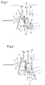
- Fig. 1 shows a first embodiment of a weaving machine for Manufacture of leno fabrics according to the present invention.
- the weaving machine comprises a lathe device and a Advised 2 to strike a registered weft thread.
- the Rotary device comprises guide elements 7 and a deflection element 5, 5 ' for upright threads 4 and leno thread guide elements 8, 8 'to form a Shed 6 and for making the leno weave.
- the shed 6 includes in the following not only that between reed 2 and stop edge Front compartment, but the entire area between the standing and Leno threads 3, 3 ', 4, which are raised at different levels and / or include lowered upright and leno threads.
- the Stand thread guide elements 7 are in the embodiment as a needle bar with upright lamellas, which are provided with eyelets at the free end.
- the loom includes an integrated loom Cleaning device with several nozzles 10.2, 10.2, 11, 11 '.
- the first Embodiment are between the reed 2 and the Leno thread guide elements 8, 8 'two nozzles 10.1, fed with compressed air, 10.2 arranged, which are directed from above against the shed 6, wherein one of the two nozzles 10.1 between the reed 2 and the Thread guide elements 7 is arranged and the other nozzle 10.2 between the upright thread and the leno thread guide elements 7, 8, 8 '.
- the two nozzles 10.1, 10.2 one can pass through the shed 6 from above downward compressed air flow 16.1, 16.2 are generated.
- a Another nozzle 11 is in the lower region of the upright thread guide elements 7 arranged by means of which against the upright thread guide elements 7 and / or the deflection element 5 directed compressed air flow 17 are generated can.
- the latter is preferably directed essentially horizontally.
- the deflection element 5 ' is offset from the Thread guide elements 7 arranged.
- the integrated cleaning device comprises a suction nozzle 13 which below the shed 6 and preferably in the area of Deflection element 5 is arranged.
- the suction nozzle 13 By means of the suction nozzle 13 one of Generated by the shed 6 downward suction air flow 19 become.
- the suction air flow supports 19 the cleaning effect of the compressed air streams 16.1, 16.2 acting from above and serves to remove the blown fiber fly from the weaving machine remove.
- a single suction nozzle 13 can advantageously a number of suction nozzles 13 and / or a suction channel are provided, which are horizontal and transverse to the direction of the upright and leno threads 3, 3 ', 4 are arranged.
- the exemplary embodiment includes the integrated cleaning device Compressed air blower 9, which is directed against the shed 6 from above Nozzles 10.1, 10.2 supplied with compressed air.
- the air blower 9 is can be moved together with the nozzles 10.1, 10.2 on a traverse 20 attached so that the nozzles parallel to the longitudinal direction of the reed 2, 2 ' can be moved.
- the sliding arrangement of the nozzles enables cleaning across the entire weaving width.
- the one in the bottom Area of the thread guide elements 7 arranged nozzle 11, by means of which one against the upright thread guide elements 7 and / or that Deflection element 5 directed compressed air flow 17 can be generated as stationary slot nozzle with horizontal slot arrangement executed. Alternatively, you can also use one in the longitudinal direction at this point of reed 2, 2 'movable nozzle 11 may be provided.
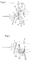
- FIG. 6 shows an enlarged section of the nozzle arrangement to that in FIG Fig. 5 shown embodiment.
- the reed is in Fig. 6 in Stop position 2 'shown.
- the position of the is also shown Thread guide elements 7 ', the deflecting element 5' and the Leno thread guide elements 8 'and the position 3', 4 'of the upright and Leno threads when the reed is in the stop position 2 '.
- a second embodiment of the present invention which is shown in Fig. 3, the orientation of the upright thread guide elements 7 compared to the first embodiment, i.e. the Attachment of the upright thread guide elements is now on top and the Eyelets of the standing needles are now arranged at the lower end.
- the second Embodiment includes three integrated cleaning device Compressed air fed nozzles 10.1-10.3, which are between the reed 2 and the Leno thread guide elements 8, 8 'arranged and from above against Shed 6 are directed, with one of the three nozzles 10.1 between the reed 2 and the thread guide elements 7 is arranged and each a nozzle 10.2, 10.3 before and after the deflecting element 5.
- nozzles 10.1-10.3 can be a downward from above through the shed 6 Compressed air flow 16.1 are generated.
- Another nozzle 11 is in the lower Area of the thread guide elements 7 arranged, by means of which a directed towards the eyelets of the upright thread guide elements 7 Compressed air stream 17 can be generated.
- the integrated cleaning device in the second Embodiment provided with a suction nozzle 13 which below the Shed 6 and preferably between the upright and Leno thread guide elements 7, 8, 8 'is arranged.
- a suction nozzle 13 By means of the suction nozzle 13 can be directed from above through the shed 6 downwards Suction air flow 19 are generated.
- the suction air flow 19 the cleaning effect of the acting from above Compressed air flow 16.1 and serves to blow the blown fiber from the Remove loom.
- a single suction nozzle 13 can advantageously a number of suction nozzles 13 and / or a suction channel are provided, which are horizontal and transverse to the direction of the standing round Leno threads 3, 3 ', 4 are arranged.
- Fig. 4 shows a third embodiment of the present invention, in which the integrated cleaning device one or more nozzles 12.1 includes seen in the direction of the upright and leno threads 3, 3 ', 4 before the thread guide elements 7 are arranged.
- the nozzles are 12.1 arranged such that the nozzles between the upright and the Leno threads an essentially horizontal stream of compressed air across Direction of the upright and leno threads can be generated.
- the nozzles 12.1 are preferably in a row between the upright and Leno threads arranged.
- the nozzles 12.1 executed as relay nozzles, the nozzles being cyclical, in the sense of a Compressed air are applied to the moving field.
- nozzle or nozzles 12.1 can accumulate fiber flights, especially larger ones Collections in the area of the shed between the standing and Leno threads are included, blown out to the selvedge and be removed.
- Fig. 4 additionally shows two variants with one second arrangement 12.2 and third arrangement 12.3 of the nozzles, by means of which is a substantially horizontal flow of compressed air across Direction of the upright and leno threads can be generated.
- the second arrangement 12.2 are the nozzles as in the basic variant of the third Embodiment in the direction of the upright and leno threads 3, 3 ', 4th seen in front of the upright thread guide elements 7 and in the third arrangement 12.3 between the reed 2 and the Standard thread guide elements 7.
- the deflecting element 5 of the leno device as part of the integrated cleaning device.
- the deflection element 5 is closed pressurized with compressed air for this purpose and includes nozzles 12.1-12.4 Removal of fiber fly from the area around the deflecting element and out the shed 6.
- the nozzle openings are of the nozzles 12.1-12.4 are inserted directly into the deflecting element, while in the variant shown in FIG. 7B, the nozzle openings of the nozzles 12. 1, 12.2 are arranged at a distance from the deflecting element.
- the deflecting element 5 also comprises nozzles 12.1-12.4, by means of which essentially between the upright and leno threads (3, 3 ', 4, 4') horizontal compressed air flow transverse to the direction of the upright and Leno threads can be generated.
- the weaving machine comprises according to one of the above-described embodiments, a controller to the Operation of the compressed air and / or suction nozzles of the integrated Control cleaning device, for example by the nozzles be activated periodically, cyclically, one after the other and / or as required. This allows an economically optimal operation of the cleaning device.
- FIG. 8 shows a top view of a weaving mill with a plurality of Weaving machines 1, 1 'and a traveling cleaner 31.
- the traveling cleaner 31 is slidably attached to a guide, the guide such is trained that the traveling cleaner when moving over all Weaving machines is performed.
- the weaving machine 1, 1 ' is preferably included an integrated cleaning device according to one of the above described exemplary embodiments equipped and with a controller, which is suitable, the integrated cleaning device in coordination with to activate the traveling cleaner 31.
- the weaving machine is equipped with an internal Cleaning device equipped, which comprises a blower 9, the is slidably arranged on a cross member 20 of the weaving machine.
- the Wanderrier comprises compressed air nozzles 32 which act on the top of the Weaving machine are directed, and suction nozzles 33, which are just above the Bottom are arranged around those blown away by the compressed air nozzles 32 Pick up impurities.
- the internal Cleaning device of the weaving machine 1 activated when the Traveling cleaner 31 approaches the loom.
- a first embodiment of a method according to the invention for Cleaning a weaving machine for the production of leno fabrics is carried out in the Described below with reference to FIGS. 1, 2 and 4.
- the weaving machine comprises in a known manner a leno device with leno elements 5, 7, 8, 8 'to form a shed 6.
- the process is characterized by this from that contamination in the area of the leno device and / or the Shed by means of an integrated in the weaving machine Cleaning device can be removed.
- the shed 6 in known manner from upright threads 4, 4 'and leno threads 3, 3' formed.
- the integrated cleaning device comprises several nozzles 12.1, by means of which in the area between the upright and leno threads, especially in the back of the shed, essentially one horizontal compressed air flow transverse to the direction of the upright and Leno threads is produced.
- the nozzles periodically and / or cyclically and / or successively and / or as required pressurized with compressed air.
- the mentioned nozzles with at least one substantially perpendicular aligned nozzle and / or with at least one essentially horizontally against the direction of the upright and leno threads aligned nozzle together.
- the integrated cleaning device of the weaving machine via a control in controlled and / or activated the weaving machine.
- the Weaving machine 1, 1 'used in a weaving mill, which weaving mill with a or several traveling cleaners 31, the integrated Cleaning device of the loom in coordination with the Wanderrilliann 31 is activated.
- the means of internal cleaning device from the shed of the weaving machine 1, 1 ' conveyed contaminants removed by the traveling cleaner 31.
Abstract
Description
Die Erfindung betrifft eine Webmaschine zur Herstellung von Drehergeweben
gemäss Oberbegriff von Anspruch 1 und ein Verfahren zum Reinigen einer
Webmaschine gemäss Oberbegriff von Anspruch 7.The invention relates to a weaving machine for producing leno fabrics
according to the preamble of
Neuere Generationen von Webmaschinen für die Herstellung von Drehergeweben, insbesondere von Drehergeweben, welche als Grundgewebe für die Teppichherstellung dienen, werden mit zunehmend höheren Drehzahlen betrieben. Die Erhöhung der Drehzahlen wurde vor allem durch die Verwendung von Luftdüsen-Schusseintragssystemen möglich, womit eine beachtliche Leistungssteigerung erzielt werden konnte. Mit dieser Leistungssteigerung nahm auch die Verunreinigung durch Faserflug zu. Je nach Art des Kettfadenmaterials bilden sich im Bereich der Drehervorrichtung, genauer gesagt an den Elementen der Drehervorrichtung, z.B. an Nadelbarren, Umlenkelementen oder Legeschienen, Ansammlungen von Faserflug. Besonders extrem ist die Faserflugbildung bei Verwendung von Fasergarnen, wie z.B. Baumwolle.Newer generations of weaving machines for the production of Leno fabrics, especially leno fabrics, which as Base fabrics used for carpet making are becoming increasingly popular operated at higher speeds. The increase in speed was before all thanks to the use of air nozzle weft insertion systems possible, with which a remarkable increase in performance could be achieved. With this increase in performance, the pollution also took off Fiber flight too. Depending on the type of warp thread material in the area of Leno device, more precisely on the elements of the leno device, e.g. on needle bars, deflection elements or laying rails, accumulations of fiber flight. Fiber flight formation is particularly extreme when used of fiber yarns, e.g. Cotton.
In einer Webmaschine zur Herstellung von Geweben mit einfachen Kettfadensystemen, wie beispielsweise Gewebe mit Leinwandbindung und deren Ableitungen, kreuzen sich die Kettfäden bei jeder neuen Fachbildung, d.h. die unteren Kettfäden kommen nach oben zu liegen und die oberen nach unten. Durch dieses Kreuzen der Kettfäden bei der Fachbildung werden grössere Ansammlungen von Faserflug im Webfach weitgehend vermieden. In a weaving machine for making fabrics with simple Warp thread systems, such as, for example, fabrics with plain weave and their derivatives, the warp threads cross with each new specialist training, i.e. the lower warp threads come to the top and the upper ones below. By crossing the warp threads during shedding Larger accumulations of fiber fly in the shed largely avoided.
Bei der Herstellung von Drehergeweben, insbesondere von Halbdrehergeweben, welche als Grundgewebe für die Teppichherstellung dienen, liegen im Webfach immer die selben Kettfäden oben beziehungsweise unten. Die Steher- und die Dreherfäden werden nach einem Schusseintrag nur soweit gegeneinander angehoben, als es für den Seitenwechsel der Dreherfäden notwendig ist. Der Faserflug kann sich so an den Elementen der Drehervorrichtung ungehindert ansammeln. Dies trifft insbesondere für den hinteren Bereich des Webfaches zu. Grössere Ansammlungen, welche sich von den Elementen der Drehervorrichtung lösen, sind zusätzlich im Bereich des Webfaches zwischen den Steher- und Dreherfäden eingeschlossen und lassen sich von dort nur mit Mühe entfernen.In the production of leno fabrics, especially of Semi-leno fabrics, which are used as the base fabric for carpet production serve, the same warp threads are always on top in the shed respectively below. The upright and leno threads are after one Weft entry raised against each other only as far as it is for the Lateral change of the leno threads is necessary. The fiber flight can look like this collect the elements of the lathe device unhindered. This is true especially for the rear area of the shed too. bigger Accumulations that separate from the elements of the lathe device, are also in the area of the shed between the upright and Includes leno threads and can only be removed from there with difficulty remove.
Zur Vermeidung von Verstopfungen in den Fadenpassagen der Drehervorrichtung, sowie von hieraus resultierenden Fadenbrüchen und entsprechenden längeren Stillstandszeiten der Webmaschinen, müssen die neueren Webmaschinen für die Herstellung von Drehergeweben vorsorglich zwecks Entfernung von Faserflugansammlungen angehalten werden. Dies ist zeitaufwendig und vermindert die Webleistung. Sogenannte Wanderreiniger (Overheadcleaners), wie sie aus dem Stand der Technik bekannt sind, ergeben in den kritischen Bereichen der Drehervorrichtung einen nur ungenügenden Reinigungseffekt.To avoid blockages in the thread passages of the Leno device, and resulting thread breaks and corresponding longer downtimes of the weaving machines, the as a precautionary measure for new weaving machines for the production of leno fabrics stopped to remove fiber fly accumulations. This is time consuming and reduces weaving performance. So-called hiking cleaners (Overhead cleaners), as are known from the prior art, only result in the critical areas of the leno device insufficient cleaning effect.
Aufgabe der Erfindung ist es, eine Webmaschine zur Herstellung von Drehergeweben zur Verfügung zu stellen, welche zum Reinigen der Drehervorrichtung und des Webfaches nicht angehalten werden muss. Eine weitere Aufgabe der Erfindung ist es, ein Verfahren zum Reinigen einer Webmaschine zur Herstellung von Drehergeweben zur Verfügung zu stellen, mittels welchem Verunreinigungen der Drehervorrichtung und des Webfaches wirkungsvoll entfernt werden können.The object of the invention is to produce a weaving machine To provide leno fabrics which are used to clean the Turning device and the shed does not have to be stopped. A Another object of the invention is a method for cleaning a To provide weaving machines for the production of leno fabrics, by means of which contamination of the leno device and the shed can be removed effectively.
Diese Aufgabe wird erfindungsgemäss durch die in Anspruch 1 definierte
Webmaschine gelöst sowie durch das in Anspruch 7 definierte Verfahren.According to the invention, this object is defined by that in
Die erfindungsgemässe Webmaschine zur Herstellung von Drehergeweben umfasst eine Drehervorrichtung mit Dreherelementen zur Bildung eines Webfaches. Zusätzlich umfasst die Webmaschine eine in die Webmaschine integrierte Reinigungsvorrichtung zum Entfernen von Verunreinigungen im Bereich der Drehervorrichtung und/oder des Webfaches.The weaving machine according to the invention for producing leno fabrics comprises a leno device with leno elements to form a Shed. In addition, the loom includes one in the loom Integrated cleaning device for removing impurities in the Area of the lathe device and / or the shed.
In einer bevorzugten Ausführungsform ist die Webmaschine in bekannter Weise mit einem Riet ausgestattet, und die Dreherelemente umfassen Führungselemente und ein Umlenkelement für Steherfäden sowie Dreherfadenführungselemente. In der bevorzugten Ausführungsform umfasst die integrierte Reinigungsvorrichtung eine oder mehrere Düsen, mittels welchen im Bereich zwischen den Steher- und den Dreherfäden, insbesondere im hinteren Teil des Webfaches, ein im Wesentlichen horizontaler Druckluftstrom quer zur Laufrichtung der Steher- und Dreherfäden erzeugbar ist. In einer weiteren bevorzugten Ausführungsform umfasst die integrierte Reinigungsvorrichtung mindestens eine Düse, welche zwischen dem Riet und den Dreherfadenführungselementen angeordnet ist, und mittels welcher ein von oben durch das Webfach nach unten gerichteter Druckluftstrom oder Saugluftstrom erzeugbar ist. In einer weiteren bevorzugten Ausführungsform umfasst die integrierte Reinigungsvorrichtung mindestens eine Düse, welche im unteren Bereich der Dreherelemente angeordnet ist, und mittels welcher ein gegen die Dreherelemente gerichteter Druckluftstrom oder Saugluftstrom erzeugbar ist.In a preferred embodiment, the weaving machine is known Way equipped with a reed, and include the leno elements Guide elements and a deflection element for upright threads as well Leno thread guide elements. In the preferred embodiment comprises the integrated cleaning device one or more nozzles, by means of which in the area between the upright and leno threads, especially in the back of the shed, essentially one horizontal compressed air flow transverse to the direction of the upright and Leno threads can be produced. In a further preferred embodiment the integrated cleaning device comprises at least one nozzle, which is arranged between the reed and the leno thread guide elements, and by means of which one is directed downwards through the shed from above Compressed air flow or suction air flow can be generated. In another preferred embodiment comprises the integrated cleaning device at least one nozzle, which in the lower area of the leno elements is arranged, and by means of which a directed against the leno elements Compressed air flow or suction air flow can be generated.
In einer Ausführungsvariante umfasst die Reinigungsvorrichtung zwei mit Druckluft gespeiste Düsen, die zwischen dem Riet und den Dreherfadenführungselementen angeordnet sind, und die von oben gegen das Webfach gerichtet sind, wobei eine der beiden Düsen zwischen dem Riet und den Steherfadenführungselementen angeordnet ist und die andere Düse zwischen den Steherfaden- und den Dreherfadenführungselementen. In einer weiteren Ausführungsvariante umfasst die Reinigungsvorrichtung mindestens zwei Düsen, von denen eine Düse eine im Wesentlichen horizontale Strahlrichtung aufweist und eine Düse eine im Wesentlichen vertikale Strahlrichtung.In one embodiment variant, the cleaning device includes two Compressed air fed nozzles between the reed and the Leno thread guide elements are arranged, and from above against the shed are directed, with one of the two nozzles between the reed and the upright thread guide elements is arranged and the other nozzle between the main thread and the leno thread guide elements. In a Another embodiment variant comprises at least the cleaning device two nozzles, one of which is a substantially horizontal one Has jet direction and a nozzle a substantially vertical Beam direction.
Vorzugsweise umfasst die integrierte Reinigungsvorrichtung mindestens eine Düse, die in Längsrichtung des Rietes bewegbar angeordnet ist. Vorzugsweise umfasst die integrierte Reinigungsvorrichtung mindestens eine Düse, die als stationär angeordnete Schlitzdüse mit horizontaler Schlitzanordnung ausgeführt ist. Vorzugsweise umfasst die integrierte Reinigungsvorrichtung eine oder mehrere stationär angebrachte Saugdüsen und/oder einen Saugkanal, die unterhalb des Webfaches quer zur Laufrichtung der Steher- und Dreherfäden angeordnet sind.The integrated cleaning device preferably comprises at least one Nozzle that is movably arranged in the longitudinal direction of the reed. The integrated cleaning device preferably comprises at least one Nozzle, which is arranged as a stationary slot nozzle with horizontal Slot arrangement is executed. Preferably, the integrated comprises Cleaning device one or more stationary suction nozzles and / or a suction channel that runs transversely below the shed Direction of the upright and leno threads are arranged.
Vorzugsweise ist das Umlenkelement in der Drehervorrichtung der Webmaschine mit Druckluft beaufschlagt und umfasst Düsen, mittels welchen im Bereich zwischen den Steher- und den Dreherfäden ein im Wesentlichen horizontaler Druckluftstrom quer zur Laufrichtung der Steher- und Dreherfäden erzeugbar ist.The deflection element in the leno device is preferably the Loom pressurized with compressed air and includes nozzles, by means of which essentially in the area between the upright and leno threads horizontal compressed air flow transverse to the direction of the upright and Leno threads can be produced.
In einer weiteren bevorzugten Ausführungsform umfasst die Webmaschine eine Steuerung, um den Betrieb der Druckluft- und/oder Saugdüsen der integrierten Reinigungseinrichtung zu steuern und um die Düsen der integrierten Reinigungseinrichtung zu aktivieren. Vorzugsweise ermöglicht die Steuerung, die Düsen periodisch und/oder zyklisch und/oder nacheinander und/oder bedarfsweise zu aktivieren.In a further preferred embodiment, the weaving machine comprises a controller to operate the compressed air and / or suction nozzles integrated cleaning device and to control the nozzles of the to activate the integrated cleaning device. Preferably, the Control, the nozzles periodically and / or cyclically and / or in succession and / or to activate if necessary.
Vorzugsweise ist die Webmaschine in einer Weberei einsetzbar, welche Weberei mit einem oder mehreren Wanderreinigern ausgestattet ist, wobei die genannte Steuerung geeignet ist, die integrierte Reinigungseinrichtung der Webmaschine in Abstimmung mit den Wanderreinigern zu aktivieren.The weaving machine can preferably be used in a weaving mill, which Weaving mill is equipped with one or more traveling cleaners, the Control is suitable, the integrated cleaning device Activate the weaving machine in coordination with the cleaning agents.
Das erfindungsgemässe Verfahren zum Reinigen einer Webmaschine zur Herstellung von Drehergeweben, welche Webmaschine eine Drehervorrichtung mit Dreherelementen zur Bildung eines Webfaches umfasst, zeichnet sich dadurch aus, dass Verunreinigungen im Bereich der Drehervorrichtung und/oder des Webfaches mittels einer in die Webmaschine integrierten Reinigungsvorrichtung entfernt werden.The inventive method for cleaning a weaving machine Production of leno fabrics, which weaving machine one Turner device with leno elements to form a shed is characterized by the fact that impurities in the area of Lathe device and / or the shed by means of a in the loom integrated cleaning device can be removed.
In einer bevorzugten Ausführungsform des Verfahrens wird die integrierte Reinigungsvorrichtung der Webmaschine über eine Steuerung in der Webmaschine aktiviert. Vorzugsweise wird die Webmaschine in einer Weberei eingesetzt, welche Weberei mit einem oder mehreren Wanderreinigern ausgestattet ist, wobei die integrierte Reinigungsvorrichtung der Webmaschine in Abstimmung mit den Wanderreinigern aktiviert wird. Vorzugsweise werden die mittels der internen Reinigungsvorrichtung aus dem Webfach geförderten Verunreinigungen durch Wanderreiniger entfernt.In a preferred embodiment of the method, the integrated Cleaning device of the weaving machine via a control in the Weaving machine activated. Preferably, the loom is in one Weaving used, which weaving with one or more Hiking cleaners are equipped with the integrated cleaning device the weaving machine is activated in coordination with the traveling cleaners. Preferably, by means of the internal cleaning device from the Shed-conveyed dirt removed by traveling cleaners.
In einer weiteren bevorzugten Ausführungsform des Verfahrens wird das Webfach in bekannter Weise aus Steherfäden und Dreherfäden gebildet. Zusätzlich umfasst die integrierte Reinigungsvorrichtung mehrere Düsen, mittels welchen im Bereich zwischen den Steher- und den Dreherfäden, insbesondere im hinteren Teil des Webfaches, ein im Wesentlichen horizontaler Druckluftstrom quer zur Laufrichtung der Steher- und Dreherfäden erzeugt wird. Vorzugsweise werden die Düsen periodisch und/oder zyklisch und/oder nacheinander und/oder bedarfsweise mit Druckluft beaufschlagt werden. Vorzugsweise wirken die genannten Düsen mit wenigstens einer im Wesentlichen senkrecht ausgerichteten Düse und/oder mit wenigstens einer im Wesentlichen horizontal entgegen der Laufrichtung der Steher- und den Dreherfäden ausgerichteten Düse zusammen.In a further preferred embodiment of the method, the Loom formed in a known manner from upright and leno threads. In addition, the integrated cleaning device includes several nozzles, by means of which in the area between the upright and leno threads, especially in the back of the shed, essentially one horizontal compressed air flow transverse to the direction of the upright and Leno threads is produced. Preferably the nozzles are periodic and / or cyclically and / or successively and / or if necessary with compressed air be charged. The said nozzles preferably cooperate at least one substantially vertically oriented nozzle and / or with at least one essentially horizontal against the direction of travel the nozzle aligned with the upright and leno threads.
Mittels der in die erfindungsgemässe Webmaschine integrierten Reinigungsvorrichtung und insbesondere mittels der beschriebenen Düsenanordnungen können Verunreinigungen im Bereich der Drehervorrichtung und des Webfaches wirkungsvoll entfernt werden. Eine vorteilhafte Reinigungswirkung ergibt sich, wenn Düsen mit unterschiedlicher Anordnung und/oder mit unterschiedlicher Orientierung der Druckluftund/oder Saugluftströme kombiniert werden, beispielsweise eine oder mehrere Düsen mit im Wesentlichen vertikal gerichteten Druckluft- und/oder Saugluftströmen mit einer oder mehreren Düsen mit im Wesentlichen horizontal gerichteten Druckluft- und/oder Saugluftströmen. Besonders vorteilhaft ist eine Düsenanordnung, mittels welcher zwischen den Steherund den Dreherfäden ein im Wesentlichen horizontaler Druckluftstrom quer zur Laufrichtung der Steher- und Dreherfäden erzeugbar ist und mittels welchen Verunreinigungen, insbesondere auch Faserflugansammlungen, die im Bereich des Webfaches zwischen den Steher- und Dreherfäden eingeschlossen sind, entfernt werden können.By means of the weaving machine integrated in the invention Cleaning device and in particular by means of the described Nozzle arrangements can cause contamination in the area Turning device and the shed can be removed effectively. A advantageous cleaning effect results when nozzles with different Arrangement and / or with different orientation of the compressed air and / or Suction air flows are combined, for example one or several nozzles with essentially vertically directed compressed air and / or Essentially, suction air flows with one or more nozzles horizontally directed compressed air and / or suction air flows. Especially A nozzle arrangement, by means of which between the upright and a substantially horizontal compressed air flow across the leno threads to the direction of the upright and leno threads can be generated and by means of what impurities, in particular also fiber fly accumulations, the in the area of the shed between the upright and leno threads included, can be removed.
Weitere vorteilhafte Ausführungsformen gehen aus den abhängigen Ansprüchen und der Zeichnung hervor. Further advantageous embodiments can be found in the dependent ones Claims and the drawing.
Im Folgenden wird die Erfindung an Hand der Ausführungsbeispiele und an Hand der Zeichnung näher erläutert. Es zeigen:
- Fig. 1
- ein erstes Ausführungsbeispiel zur vorliegenden Erfindung,
- Fig. 2
- eine Ausführungsvariante mit zusätzlicher Saugdüse sowie mit gegenüber Fig. 1 abweichender Dreherfadenführung,
- Fig. 3
- ein zweites Ausführungsbeispiel zur vorliegenden Erfindung mit oben liegender Befestigung der Steherfadenführungselemente,
- Fig. 4
- ein drittes Ausführungsbeispiel zur vorliegenden Erfindung,
- Fig. 5
- eine Ausführungsvariante zum ersten Ausführungsbeispiel mit in Längsrichtung des Rietes verschiebbaren Druckluftdüsen,
- Fig. 6
- ein vergrösserter Ausschnitt der Düsenanordnung zu der in Fig. 5 gezeigten Ausführungsvariante,
- Fig. 7A
- eine Ausführungsvariante eines mit Druckluft beaufschlagten Umlenkelementes,
- Fig. 7B
- eine weitere Ausführungsvariante eines mit Druckluft beaufschlagten Umlenkelementes,
- Fig. 8
- eine Draufsicht einer Weberei mit Webmaschinen und Wanderreiniger, und
- Fig. 9
- eine Detailansicht von Fig. 8 mit Webmaschine und Wanderreiniger von der Seite gesehen.
- Fig. 1
- a first embodiment of the present invention,
- Fig. 2
- 1 variant with an additional suction nozzle and with a leno thread guide that differs from FIG. 1,
- Fig. 3
- 2 shows a second exemplary embodiment of the present invention with the upright fastening of the upright thread guide elements,
- Fig. 4
- a third embodiment of the present invention,
- Fig. 5
- 1 shows a variant of the first embodiment with compressed air nozzles that can be moved in the longitudinal direction of the reed,
- Fig. 6
- 5 shows an enlarged section of the nozzle arrangement for the embodiment variant shown in FIG. 5,
- Figure 7A
- an embodiment of a deflection element acted upon by compressed air,
- Figure 7B
- another embodiment variant of a deflection element acted upon by compressed air,
- Fig. 8
- a top view of a weaving mill with weaving machines and traveling cleaners, and
- Fig. 9
- a detailed view of Fig. 8 with weaving machine and traveling cleaner seen from the side.
In einigen Veröffentlichungen über die Herstellung von Drehergeweben sind die Bezeichnungen 'Steherfaden' und 'Dreherfaden' gegenüber der nachstehenden Beschreibung vertauscht. Auf die Ausgestaltung und Funktion der beschriebenen Webmaschine hat die Wahl der Terminologie jedoch keinen Einfluss. In some publications on the manufacture of leno fabrics are the terms 'upright thread' and 'leno thread' compared to the swapped the description below. On the design and function however, the weaving machine described has the choice of terminology no influence.
Fig. 1 zeigt ein erstes Ausführungsbeispiel einer Webmaschine zur
Herstellung von Drehergeweben gemäss der vorliegenden Erfindung. Die
Webmaschine umfasst in bekannter Weise eine Drehervorrichtung sowie ein
Riet 2 zum Anschlagen eines eingetragenen Schussfadens. Die
Drehervorrichtung umfasst Führungselemente 7 und ein Umlenkelement 5, 5'
für Steherfäden 4 sowie Dreherfadenführungselemente 8, 8' zur Bildung eines
Webfaches 6 und zur Herstellung der Dreherbindung. Das Webfach 6 umfasst
im Folgenden nicht nur das zwischen Riet 2 und Anschlagkante gelegene
Vorderfach, sondern den gesamten Bereich zwischen den Steher- und
Dreherfäden 3, 3', 4, den die auf unterschiedlichem Niveau angehobenen
und/oder abgesenkten Steher- und Dreherfäden einschliessen. Die
Steherfadenführungselemente 7 sind im Ausführungsbeispiel als Nadelbarre
mit Steherlamellen, die am freien Ende mit Ösen versehen sind, ausgelegt.
Die Dreherfadenführungselemente 8, 8' sind als Legeschiene ausgeführt. An
Stelle der Legeschiene können zur Führung der Dreherfäden 3, 3' auch eine
zweite Nadelbarre mit festen oder beweglichen Dreherlamellen und/oder
Webschäften mit Litzenösen eingesetzt werden.Fig. 1 shows a first embodiment of a weaving machine for
Manufacture of leno fabrics according to the present invention. The
In a known manner, the weaving machine comprises a lathe device and a
Advised 2 to strike a registered weft thread. The
Rotary device comprises
Zusätzlich umfasst die Webmaschine eine in die Webmaschine integrierte
Reinigungsvorrichtung mit mehreren Düsen 10.2, 10.2, 11, 11'. Im ersten
Ausführungsbeispiel sind zwischen dem Riet 2 und den
Dreherfadenführungselementen 8, 8' zwei mit Druckluft gespeiste Düsen 10.1,
10.2 angeordnet, die von oben gegen das Webfach 6 gerichtet sind, wobei
eine der beiden Düsen 10.1 zwischen dem Riet 2 und den
Steherfadenführungselementen 7 angeordnet ist und die andere Düse 10.2
zwischen den Steherfaden- und den Dreherfadenführungselementen 7, 8, 8'.
Mittels der beiden Düsen 10.1, 10.2 kann ein von oben durch das Webfach 6
nach unten gerichteter Druckluftstrom 16.1, 16.2 erzeugt werden. Eine
weitere Düse 11 ist im unteren Bereich der Steherfadenführungselemente 7
angeordnet, mittels welcher ein gegen die Steherfadenführungselemente 7
und/oder das Umlenkelement 5 gerichteter Druckluftstrom 17 erzeugt werden
kann. Vorzugsweise ist letzterer im Wesentlichen horizontal gerichtet. In einer
Ausführungsvariante ist das Umlenkelement 5' versetzt von den
Steherfadenführungselementen 7 angeordnet. Mittels einer zusätzlicher Düse
11', welche im Bereich des versetzt angeordneten Umlenkelementes 5'
vorgesehen ist, kann ein gegen das Umlenkelement gerichteter
Druckluftstrom 17' erzeugt werden.In addition, the loom includes an integrated loom
Cleaning device with several nozzles 10.2, 10.2, 11, 11 '. In the first
Embodiment are between the
In einer vorteilhaften Ausführungsvariante, welche in Fig. 2 gezeigt ist,
umfasst die integrierte Reinigungsvorrichtung eine Saugdüse 13, die
unterhalb des Webfaches 6 und vorzugsweise im Bereich des
Umlenkelementes 5 angeordnet ist. Mittels der Saugdüse 13 kann ein von
oben durch das Webfach 6 nach unten gerichteter Saugluftstrom 19 erzeugt
werden. In der gezeigten Ausführungsvariante unterstützt der Saugluftstrom
19 die Reinigungswirkung der von oben wirkenden Druckluftströme 16.1, 16.2
und dient dazu, den weggeblasenen Faserflug aus der Webmaschine zu
entfernen. An Stelle einer einzelnen Saugdüse 13 kann vorteilhafterweise
eine Reihe von Saugdüsen 13 und/oder ein Saugkanal vorgesehen werden,
welche horizontal und quer zur Laufrichtung der Steher- und Dreherfäden 3,
3', 4 angeordnet sind.In an advantageous embodiment variant, which is shown in FIG. 2,
the integrated cleaning device comprises a
In einer weiteren, in Fig. 5 gezeigten Ausführungsvariante zum ersten
Ausführungsbeispiel umfasst die integrierte Reinigungsvorrichtung ein
Druckluftgebläse 9, das die von oben gegen das Webfach 6 gerichteten
Düsen 10.1, 10.2 mit Druckluft versorgt. Das Druckluftgebläse 9 ist
zusammen mit den Düsen 10.1, 10.2 bewegbar an einer Traverse 20
befestigt, so dass die Düsen parallel zur Längsrichtung des Rietes 2, 2'
verschoben werden können. Die verschiebbare Anordnung der Düsen
ermöglicht eine Reinigung über die gesamte Webbreite. Die im unteren
Bereich der Steherfadenführungselemente 7 angeordnete Düse 11, mittels
welcher ein gegen die Steherfadenführungselemente 7 und/oder das
Umlenkelement 5 gerichteter Druckluftstrom 17 erzeugt werden kann, ist als
stationär angeordnete Schlitzdüse mit horizontaler Schlitzanordnung
ausgeführt. Alternativ kann an dieser Stelle ebenfalls eine in Längsrichtung
des Rietes 2, 2' bewegbare Düse 11 vorgesehen sein.In a further embodiment variant, shown in FIG. 5, for the first
The exemplary embodiment includes the integrated cleaning device
Compressed
Fig. 6 zeigt einen vergrösserten Ausschnitt der Düsenanordnung zu der in Fig. 5 gezeigten Ausführungsvariante. Das Riet ist in Fig. 6 in Anschlagstellung 2' gezeigt. Ebenfalls dargestellt ist die Position der Steherfadenführungselemente 7', des Umlenkelementes 5' und der Dreherfadenführungselemente 8' sowie die Lage 3', 4' der Steher- und Dreherfäden, wenn sich das Riet in der Anschlagstellung 2' befindet.FIG. 6 shows an enlarged section of the nozzle arrangement to that in FIG Fig. 5 shown embodiment. The reed is in Fig. 6 in Stop position 2 'shown. The position of the is also shown Thread guide elements 7 ', the deflecting element 5' and the Leno thread guide elements 8 'and the position 3', 4 'of the upright and Leno threads when the reed is in the stop position 2 '.
In einem zweiten Ausführungsbeispiel zur vorliegenden Erfindung, das in Fig.
3 gezeigt ist, wurde die Orientierung der Steherfadenführungselemente 7
gegenüber dem ersten Ausführungsbeispiel auf den Kopf gestellt, d.h. die
Befestigung der Steherfadenführungselemente ist nun oben liegend und die
Ösen der Stehernadeln sind nun am unteren Ende angeordnet. Im zweiten
Ausführungsbeispiel umfasst die integrierte Reinigungsvorrichtung drei mit
Druckluft gespeiste Düsen 10.1-10.3, die zwischen dem Riet 2 und den
Dreherfadenführungselementen 8, 8' angeordnet und von oben gegen das
Webfach 6 gerichtet sind, wobei eine der drei Düsen 10.1 zwischen dem Riet
2 und den Steherfadenführungselementen 7 angeordnet ist und je eine Düse
10.2, 10.3 vor und nach dem Umlenkelement 5. Mittels der drei Düsen 10.1-10.3
kann ein von oben durch das Webfach 6 nach unten gerichteter
Druckluftstrom 16.1 erzeugt werden. Eine weitere Düse 11 ist im unteren
Bereich der Steherfadenführungselemente 7 angeordnet, mittels welcher ein
gegen die Ösen der Steherfadenführungselemente 7 gerichteter
Druckluftstrom 17 erzeugt werden kann.In a second embodiment of the present invention, which is shown in Fig.
3, the orientation of the upright
Weiter ist die integrierte Reinigungsvorrichtung im zweiten
Ausführungsbeispiel mit einer Saugdüse 13 versehen, die unterhalb des
Webfaches 6 und vorzugsweise zwischen den Steherfaden- und
Dreherfadenführungselementen 7, 8, 8' angeordnet ist. Mittels der Saugdüse
13 kann ein von oben durch das Webfach 6 nach unten gerichteter
Saugluftstrom 19 erzeugt werden. Im zweiten Ausführungsbeispiel unterstützt
der Saugluftstrom 19 die Reinigungswirkung des von oben wirkenden
Druckluftstromes 16.1 und dient dazu, den weggeblasenen Faserflug aus der
Webmaschine zu entfernen. An Stelle einer einzelnen Saugdüse 13 kann
vorteilhafterweise eine Reihe von Saugdüsen 13 und/oder ein Saugkanal
vorgesehen werden, welche horizontal und quer zur Laufrichtung der Steherund
Dreherfäden 3, 3', 4 angeordnet sind.Next is the integrated cleaning device in the second
Embodiment provided with a
Fig. 4 zeigt ein drittes Ausführungsbeispiel zur vorliegenden Erfindung, in
welchem die integrierte Reinigungsvorrichtung eine oder mehrere Düsen 12.1
umfasst, die in Laufrichtung der Steher- und Dreherfäden 3, 3', 4 gesehen vor
den Steherfadenführungselementen 7 angeordnet sind. Die Düsen 12.1 sind
derart angeordnet, dass mittels der Düsen zwischen den Steher- und den
Dreherfäden ein im Wesentlichen horizontaler Druckluftstrom quer zur
Laufrichtung der Steher- und Dreherfäden erzeugt werden kann.
Vorzugsweise sind die Düsen 12.1 in einer Reihe zwischen den Steher- und
Dreherfäden angeordnet. In einer Ausführungsvariante sind die Düsen 12.1
als Stafettendüsen ausgeführt, wobei die Düsen zyklisch, im Sinne eines
Wanderfeldes mit Druckluft beaufschlagt werden. Mittels der oder den Düsen
12.1 können Faserflugansammlungen, insbesondere auch grössere
Ansammlungen, die im Bereich des Webfaches zwischen den Steher- und
Dreherfäden eingeschlossen sind, zur Webkante hin ausgeblasen und
entfernt werden. Fig. 4 zeigt zusätzlich zwei Ausführungsvarianten mit einer
zweiten Anordnung 12.2 und dritten Anordnung 12.3 der Düsen, mittels
welchen ein im Wesentlichen horizontaler Druckluftstrom quer zur
Laufrichtung der Steher- und Dreherfäden erzeugt werden kann. In der
zweiten Anordnung 12.2 sind die Düsen wie bei der Grundvariante des dritten
Ausführungsbeispiels in Laufrichtung der Steher- und Dreherfäden 3, 3', 4
gesehen vor den Steherfadenführungselementen 7 angeordnet und in der
dritten Anordnung 12.3 zwischen dem Riet 2 und den
Steherfadenführungselementen 7.Fig. 4 shows a third embodiment of the present invention, in
which the integrated cleaning device one or more nozzles 12.1
includes seen in the direction of the upright and
In zwei weiteren vorteilhaften Ausführungsvarianten, die in Fig. 7A und 7B
dargestellt sind, ist das Umlenkelement 5 der Drehervorrichtung als Teil der
integrierten Reinigungsvorrichtung ausgebildet. Das Umlenkelement 5 ist zu
diesem Zweck mit Druckluft beaufschlagt und umfasst Düsen 12.1-12.4 zur
Entfernung von Faserflug aus der Umgebung des Umlenkelementes und aus
dem Webfach 6. In der in Fig. 7A gezeigten Variante sind die Düsenöffnungen
der Düsen 12.1-12.4 direkt in das Umlenkelement eingelassen, während in
der in Fig. 7B gezeigten Variante die Düsenöffnungen der Düsen 12. 1, 12.2
beabstandet vom Umlenkelement angeordnet sind. Zweckmässigerweise
umfasst das Umlenkelement 5 auch Düsen 12.1-12.4, mittels welchen
zwischen den Steher- und den Dreherfäden (3, 3', 4, 4') ein im Wesentlichen
horizontaler Druckluftstrom quer zur Laufrichtung der Steher- und
Dreherfäden erzeugt werden kann. In two further advantageous embodiment variants, which are shown in FIGS. 7A and 7B
are shown, the deflecting
In einer bevorzugten Ausführungsform umfasst die Webmaschine gemäss einem der oben beschriebenen Ausführungsbeispiele eine Steuerung, um den Betrieb der Druckluft- und/oder Saugdüsen der integrierten Reinigungsvorrichtung zu steuern, beispielsweise indem die Düsen periodisch, zyklisch, nacheinander und/oder bedarfsweise aktiviert werden. Dies erlaubt einen wirtschaftlich optimalen Betrieb der Reinigungsvorrichtung.In a preferred embodiment, the weaving machine comprises according to one of the above-described embodiments, a controller to the Operation of the compressed air and / or suction nozzles of the integrated Control cleaning device, for example by the nozzles be activated periodically, cyclically, one after the other and / or as required. This allows an economically optimal operation of the cleaning device.
Fig. 8 zeigt eine Draufsicht einer Weberei mit einer Vielzahl von
Webmaschinen 1, 1' und einem Wanderreiniger 31. Der Wanderreiniger 31 ist
verschiebbar an einer Führung befestigt, wobei die Führung derart
ausgebildet ist, dass der Wanderreiniger beim Verschieben über sämtliche
Webmaschinen geführt wird. Vorzugsweise ist die Webmaschine 1, 1' mit
einer integrierten Reinigungsvorrichtung gemäss einem der oben
beschriebenen Ausführungsbeispiele ausgestattet und mit einer Steuerung,
welche geeignet ist, die integrierte Reinigungsvorrichtung in Abstimmung mit
dem Wanderreiniger 31 zu aktivieren.8 shows a top view of a weaving mill with a plurality of
Fig. 9 zeigt eine Seitenansicht einer Webmaschine 1 und eines
Wanderreinigers 31. Die Webmaschine ist mit einer internen
Reinigungsvorrichtung ausgestattet, welche ein Gebläse 9 umfasst, das
verschiebbar auf einer Traverse 20 der Webmaschine angeordnet ist. Der
Wanderreiniger umfasst Druckluftdüsen 32, welche von oben auf die
Webmaschine gerichtet sind, und Saugdüsen 33, welche knapp über dem
Boden angeordnet sind, um die von den Druckluftdüsen 32 weggeblasenen
Verunreinigungen aufzunehmen. Vorteilhafterweise wird die interne
Reinigungsvorrichtung der Webmaschine 1 aktiviert, wenn sich der
Wanderreiniger 31 der Webmaschine nähert.9 shows a side view of a weaving
Ein erstes Ausführungsbeispiel eines erfindungsgemässen Verfahrens zum
Reinigen einer Webmaschine zur Herstellung von Drehergeweben wird im
Folgenden anhand der Figuren 1, 2 und 4 beschrieben. Die Webmaschine
umfasst in bekannter Weise eine Drehervorrichtung mit Dreherelementen 5, 7,
8, 8' zur Bildung eines Webfaches 6. Das Verfahren zeichnet sich dadurch
aus, dass Verunreinigungen im Bereich der Drehervorrichtung und/oder des
Webfaches mittels einer in die Webmaschine integrierten
Reinigungsvorrichtung entfernt werden. A first embodiment of a method according to the invention for
Cleaning a weaving machine for the production of leno fabrics is carried out in the
Described below with reference to FIGS. 1, 2 and 4. The weaving machine
comprises in a known manner a leno device with
In einer bevorzugten Ausführungsform des Verfahrens wird das Webfach 6 in
bekannter Weise aus Steherfäden 4, 4' und Dreherfäden 3, 3' gebildet.
Zusätzlich umfasst die integrierte Reinigungsvorrichtung mehrere Düsen 12.1,
mittels welchen im Bereich zwischen den Steher- und den Dreherfäden,
insbesondere im hinteren Teil des Webfaches, ein im Wesentlichen
horizontaler Druckluftstrom quer zur Laufrichtung der Steher- und
Dreherfäden erzeugt wird. In einer Ausführungsvariante werden die Düsen
periodisch und/oder zyklisch und/oder nacheinander und/oder bedarfsweise
mit Druckluft beaufschlagt. In einer weiteren Ausführungsvariante wirken die
genannten Düsen mit wenigstens einer im Wesentlichen senkrecht
ausgerichteten Düse und/oder mit wenigstens einer im Wesentlichen
horizontal entgegen der Laufrichtung der Steher- und den Dreherfäden
ausgerichteten Düse zusammen.In a preferred embodiment of the method, the
In einer weiteren bevorzugten Ausführungsform des Verfahrens wird die
integrierte Reinigungsvorrichtung der Webmaschine über eine Steuerung in
der Webmaschine gesteuert und/oder aktiviert. In einer Ausführungsvariante,
die im Folgenden anhand der Figuren 8 und 9 näher erläutert ist, wird die
Webmaschine 1, 1' in einer Weberei eingesetzt, welche Weberei mit einem
oder mehreren Wanderreinigern 31 ausgestattet ist, wobei die integrierte
Reinigungsvorrichtung der Webmaschine in Abstimmung mit den
Wanderreinigern 31 aktiviert wird. Vorteilhafterweise werden die mittels der
internen Reinigungsvorrichtung aus dem Webfach der Webmaschine 1, 1'
geförderten Verunreinigungen durch die Wanderreiniger 31 entfernt.In a further preferred embodiment of the method, the
integrated cleaning device of the weaving machine via a control in
controlled and / or activated the weaving machine. In one variant,
which is explained in more detail below with reference to FIGS. 8 and 9, the
Claims (12)
wobei eine oder mehrere der Düsen (12.1-12.4) derart angeordnet sind, dass mittels der Düsen (12.1-12.4) im Bereich zwischen den Steher- und den Dreherfäden (3, 3', 4, 4'), insbesondere im hinteren Teil des Webfaches (6), ein im Wesentlichen horizontaler Druckluftstrom (18.1-18.4) quer zur Laufrichtung der Steher- und Dreherfäden erzeugbar ist, und/oder
wobei mindestens eine der Düsen (10.1-10.3,13), mittels welcher ein von oben durch das Webfach (6) nach unten gerichteter Druckluftstrom (16.1, 16.2) oder Saugluftstrom (19) erzeugbar ist, zwischen dem Riet (2, 2') und den Dreherfadenführungselementen (8, 8') angeordnet ist, und/oder
wobei mindestens eine der Düsen (11, 11'), mittels welcher ein gegen die Dreherelemente (5, 5', 7, 7', 8, 8') gerichteter Druckluftstrom (17, 17') oder Saugluftstrom erzeugbar ist, im unteren Bereich der Dreherelemente angeordnet ist.Loom according to claim 1, wherein the loom (1, 1 ') is equipped in a known manner with a reed (2, 2'), and wherein the leno elements guide elements (7, 7 ') and a deflecting element (5, 5') for Stand threads (4, 4 ') and leno thread guide elements (8, 8'), characterized in that the integrated cleaning device comprises one or more nozzles (10.1-10.3, 11, 11 ', 12.1-12.4, 13),
wherein one or more of the nozzles (12.1-12.4) are arranged such that by means of the nozzles (12.1-12.4) in the area between the upright and leno threads (3, 3 ', 4, 4'), in particular in the rear part of the Shed (6), a substantially horizontal compressed air flow (18.1-18.4) transverse to the running direction of the upright and leno threads can be generated, and / or
At least one of the nozzles (10.1-10.3, 13), by means of which a compressed air stream (16.1, 16.2) or suction air stream (19) directed downwards through the shed (6) can be generated, between the reed (2, 2 ') and the leno thread guide elements (8, 8 ') is arranged, and / or
at least one of the nozzles (11, 11 '), by means of which a compressed air flow (17, 17') or suction air flow directed against the leno elements (5, 5 ', 7, 7', 8, 8 ') can be generated, in the lower region the leno elements are arranged.
Priority Applications (1)
| Application Number | Priority Date | Filing Date | Title |
|---|---|---|---|
| EP20030405651 EP1405943B1 (en) | 2002-10-04 | 2003-09-08 | Loom for producing leno fabrics |
Applications Claiming Priority (3)
| Application Number | Priority Date | Filing Date | Title |
|---|---|---|---|
| EP02405859 | 2002-10-04 | ||
| EP02405859 | 2002-10-04 | ||
| EP20030405651 EP1405943B1 (en) | 2002-10-04 | 2003-09-08 | Loom for producing leno fabrics |
Publications (3)
| Publication Number | Publication Date |
|---|---|
| EP1405943A2 true EP1405943A2 (en) | 2004-04-07 |
| EP1405943A3 EP1405943A3 (en) | 2005-08-10 |
| EP1405943B1 EP1405943B1 (en) | 2008-04-30 |
Family
ID=31995548
Family Applications (1)
| Application Number | Title | Priority Date | Filing Date |
|---|---|---|---|
| EP20030405651 Expired - Lifetime EP1405943B1 (en) | 2002-10-04 | 2003-09-08 | Loom for producing leno fabrics |
Country Status (1)
| Country | Link |
|---|---|
| EP (1) | EP1405943B1 (en) |
Cited By (1)
| Publication number | Priority date | Publication date | Assignee | Title |
|---|---|---|---|---|
| CN102773385A (en) * | 2012-07-25 | 2012-11-14 | 浙江旷达纺织机械有限公司 | Line cutting part of camb-aligning device for harness assembling |
Citations (8)
| Publication number | Priority date | Publication date | Assignee | Title |
|---|---|---|---|---|
| DE1679571A1 (en) * | 1966-08-23 | 1971-04-08 | Parks Cramer Co | Facility for cleaning looms |
| DE1710296A1 (en) * | 1967-03-17 | 1971-10-21 | Luwa Ag | Pneumatic cleaning device for a weaving machine |
| DE2755449A1 (en) * | 1977-11-07 | 1979-05-10 | Sulzer Ag | WEB MACHINE |
| US4678012A (en) * | 1986-08-04 | 1987-07-07 | Graham Walker O | Cleaning and yarn conditioning system for weaving machines |
| EP0596571A1 (en) * | 1992-11-04 | 1994-05-11 | STARTES JACQUARD s.r.l. | Air-blow cleaning device for looms |
| US5910598A (en) * | 1994-11-02 | 1999-06-08 | Shofner Engineering Associates, Inc. | Modular process zone and personnel zone environmental control with dedicated air jet cleaning |
| FR2784398A1 (en) * | 1998-10-09 | 2000-04-14 | Icbt Diederichs Sa | Cleaning of looms during operation, is a process of blowing fibrous flocks and fluff away using upwardly-directed low pressure air jet array below warp shed, and horizontally-directed jet array to one side of machine |
| DE10057692A1 (en) * | 2000-01-29 | 2002-05-29 | Dornier Gmbh Lindauer | Weaving machine for producing a leno fabric |
-
2003
- 2003-09-08 EP EP20030405651 patent/EP1405943B1/en not_active Expired - Lifetime
Patent Citations (8)
| Publication number | Priority date | Publication date | Assignee | Title |
|---|---|---|---|---|
| DE1679571A1 (en) * | 1966-08-23 | 1971-04-08 | Parks Cramer Co | Facility for cleaning looms |
| DE1710296A1 (en) * | 1967-03-17 | 1971-10-21 | Luwa Ag | Pneumatic cleaning device for a weaving machine |
| DE2755449A1 (en) * | 1977-11-07 | 1979-05-10 | Sulzer Ag | WEB MACHINE |
| US4678012A (en) * | 1986-08-04 | 1987-07-07 | Graham Walker O | Cleaning and yarn conditioning system for weaving machines |
| EP0596571A1 (en) * | 1992-11-04 | 1994-05-11 | STARTES JACQUARD s.r.l. | Air-blow cleaning device for looms |
| US5910598A (en) * | 1994-11-02 | 1999-06-08 | Shofner Engineering Associates, Inc. | Modular process zone and personnel zone environmental control with dedicated air jet cleaning |
| FR2784398A1 (en) * | 1998-10-09 | 2000-04-14 | Icbt Diederichs Sa | Cleaning of looms during operation, is a process of blowing fibrous flocks and fluff away using upwardly-directed low pressure air jet array below warp shed, and horizontally-directed jet array to one side of machine |
| DE10057692A1 (en) * | 2000-01-29 | 2002-05-29 | Dornier Gmbh Lindauer | Weaving machine for producing a leno fabric |
Cited By (2)
| Publication number | Priority date | Publication date | Assignee | Title |
|---|---|---|---|---|
| CN102773385A (en) * | 2012-07-25 | 2012-11-14 | 浙江旷达纺织机械有限公司 | Line cutting part of camb-aligning device for harness assembling |
| CN102773385B (en) * | 2012-07-25 | 2015-06-03 | 浙江旷达纺织机械有限公司 | Line cutting part of camb-aligning device for harness assembling |
Also Published As
| Publication number | Publication date |
|---|---|
| EP1405943B1 (en) | 2008-04-30 |
| EP1405943A3 (en) | 2005-08-10 |
Similar Documents
| Publication | Publication Date | Title |
|---|---|---|
| EP2531639B1 (en) | Loom for producing woven fabrics having added weft effects | |
| EP0778364B1 (en) | Process and loom for handling a weft thread | |
| CH618481A5 (en) | Method for the insertion of weft threads by means of a weft-inserting lamellar comb of a jet-weaving machine and weft-inserting lamellar comb for carrying out this method | |
| EP1120485B1 (en) | Loom for weaving a leno cloth | |
| DE2700119C2 (en) | Jet loom | |
| EP0021128A1 (en) | Reed for air-jet loom | |
| DE1710213A1 (en) | Process and device for the production of plush fabrics | |
| EP1122345A1 (en) | Method for producing a base leno fabric and loom for carrying out said method | |
| DE2529763A1 (en) | WEAVING MACHINE WITH DEVICE FOR ENTRYING THE WEFT FEEDS BY USING A FLUID | |
| DE102010034969B3 (en) | Weaving and weaving machine for weaving patterns in fabrics with additional pattern effects | |
| EP0562213B1 (en) | Pneumatic selvedge-forming device for looms | |
| EP0610881A1 (en) | Seam-weaving loom with fringe gripper | |
| DE19925171A1 (en) | Circular knitting machine | |
| CH671590A5 (en) | ||
| CH584302A5 (en) | Pneumatic cleaning device for tape-weaving machine - formed by blower pipe located below shed and a suction hood disposed above shed over pipe | |
| EP1405943B1 (en) | Loom for producing leno fabrics | |
| EP1012364B1 (en) | Thread controlling assembly | |
| EP1255885B1 (en) | Method for deflecting a warp thread sheet during weaving and a weaving machine | |
| EP0786547B1 (en) | Process and device to form tuck-in selvedges | |
| DE1735022B2 (en) | Pneumatic cleaning device for looms | |
| EP1101850A1 (en) | Device to form a leno weave | |
| EP0527972B1 (en) | Gripper-shuttle loom | |
| EP0676494A1 (en) | Device for diminishing lint in looms | |
| CH681636A5 (en) | ||
| EP1512782B1 (en) | Weaving loom with a tuck-in device |
Legal Events
| Date | Code | Title | Description |
|---|---|---|---|
| PUAI | Public reference made under article 153(3) epc to a published international application that has entered the european phase |
Free format text: ORIGINAL CODE: 0009012 |
|
| AK | Designated contracting states |
Kind code of ref document: A2 Designated state(s): AT BE BG CH CY CZ DE DK EE ES FI FR GB GR HU IE IT LI LU MC NL PT RO SE SI SK TR |
|
| AX | Request for extension of the european patent |
Extension state: AL LT LV MK |
|
| PUAL | Search report despatched |
Free format text: ORIGINAL CODE: 0009013 |
|
| AK | Designated contracting states |
Kind code of ref document: A3 Designated state(s): AT BE BG CH CY CZ DE DK EE ES FI FR GB GR HU IE IT LI LU MC NL PT RO SE SI SK TR |
|
| AX | Request for extension of the european patent |
Extension state: AL LT LV MK |
|
| 17P | Request for examination filed |
Effective date: 20060112 |
|
| AKX | Designation fees paid |
Designated state(s): BE DE IT |
|
| GRAP | Despatch of communication of intention to grant a patent |
Free format text: ORIGINAL CODE: EPIDOSNIGR1 |
|
| GRAS | Grant fee paid |
Free format text: ORIGINAL CODE: EPIDOSNIGR3 |
|
| GRAA | (expected) grant |
Free format text: ORIGINAL CODE: 0009210 |
|
| AK | Designated contracting states |
Kind code of ref document: B1 Designated state(s): BE DE IT |
|
| REF | Corresponds to: |
Ref document number: 50309723 Country of ref document: DE Date of ref document: 20080612 Kind code of ref document: P |
|
| PLBE | No opposition filed within time limit |
Free format text: ORIGINAL CODE: 0009261 |
|
| STAA | Information on the status of an ep patent application or granted ep patent |
Free format text: STATUS: NO OPPOSITION FILED WITHIN TIME LIMIT |
|
| BERE | Be: lapsed |
Owner name: SULTEX A.G. Effective date: 20080930 |
|
| 26N | No opposition filed |
Effective date: 20090202 |
|
| PG25 | Lapsed in a contracting state [announced via postgrant information from national office to epo] |
Ref country code: BE Free format text: LAPSE BECAUSE OF NON-PAYMENT OF DUE FEES Effective date: 20080930 |
|
| PG25 | Lapsed in a contracting state [announced via postgrant information from national office to epo] |
Ref country code: IT Free format text: LAPSE BECAUSE OF NON-PAYMENT OF DUE FEES Effective date: 20080908 Ref country code: DE Free format text: LAPSE BECAUSE OF NON-PAYMENT OF DUE FEES Effective date: 20090401 |