EP1405942A1 - Method of tuck-in operation of a shuttleless loom and a tuck-in device - Google Patents
Method of tuck-in operation of a shuttleless loom and a tuck-in device Download PDFInfo
- Publication number
- EP1405942A1 EP1405942A1 EP20030020622 EP03020622A EP1405942A1 EP 1405942 A1 EP1405942 A1 EP 1405942A1 EP 20030020622 EP20030020622 EP 20030020622 EP 03020622 A EP03020622 A EP 03020622A EP 1405942 A1 EP1405942 A1 EP 1405942A1
- Authority
- EP
- European Patent Office
- Prior art keywords
- tuck
- weft
- loom
- nozzle
- airflow
- Prior art date
- Legal status (The legal status is an assumption and is not a legal conclusion. Google has not performed a legal analysis and makes no representation as to the accuracy of the status listed.)
- Granted
Links
- 238000000034 method Methods 0.000 title claims abstract description 20
- 238000002347 injection Methods 0.000 claims abstract description 48
- 239000007924 injection Substances 0.000 claims abstract description 48
- 239000004744 fabric Substances 0.000 claims abstract description 24
- 235000014676 Phragmites communis Nutrition 0.000 claims description 10
- 238000010009 beating Methods 0.000 claims description 4
- 230000002950 deficient Effects 0.000 abstract description 17
- 238000000605 extraction Methods 0.000 abstract description 2
- 238000010586 diagram Methods 0.000 description 7
- 238000001514 detection method Methods 0.000 description 5
- 230000015572 biosynthetic process Effects 0.000 description 3
- 239000000470 constituent Substances 0.000 description 3
- 230000000694 effects Effects 0.000 description 2
- 238000009941 weaving Methods 0.000 description 2
- 230000003247 decreasing effect Effects 0.000 description 1
- 230000003111 delayed effect Effects 0.000 description 1
- 230000005764 inhibitory process Effects 0.000 description 1
- 238000003780 insertion Methods 0.000 description 1
- 230000037431 insertion Effects 0.000 description 1
- 239000000463 material Substances 0.000 description 1
- 230000000717 retained effect Effects 0.000 description 1
Images


Classifications
-
- D—TEXTILES; PAPER
- D03—WEAVING
- D03D—WOVEN FABRICS; METHODS OF WEAVING; LOOMS
- D03D51/00—Driving, starting, or stopping arrangements; Automatic stop motions
- D03D51/18—Automatic stop motions
- D03D51/44—Automatic stop motions acting on defective operation of loom mechanisms
-
- D—TEXTILES; PAPER
- D03—WEAVING
- D03D—WOVEN FABRICS; METHODS OF WEAVING; LOOMS
- D03D47/00—Looms in which bulk supply of weft does not pass through shed, e.g. shuttleless looms, gripper shuttle looms, dummy shuttle looms
- D03D47/40—Forming selvedges
- D03D47/48—Forming selvedges by inserting cut end of weft in next shed, e.g. by tucking, by blowing
-
- D—TEXTILES; PAPER
- D03—WEAVING
- D03D—WOVEN FABRICS; METHODS OF WEAVING; LOOMS
- D03D51/00—Driving, starting, or stopping arrangements; Automatic stop motions
- D03D51/06—Driving, starting, or stopping arrangements; Automatic stop motions using particular methods of stopping
- D03D51/08—Driving, starting, or stopping arrangements; Automatic stop motions using particular methods of stopping stopping at definite point in weaving cycle, or moving to such point after stopping
- D03D51/085—Extraction of defective weft
Definitions
- the invention relates to a method of allowing a tuck-in device of a shuttleless loom inoperative in response to an instruction from a loom and the tuck-in device.
- JP-A 2001-159053 discloses a weft holding device of a tuck-in device.
- the weft holding device of the tuck-in device injects air form a tuck-in nozzle (release port) provided inside a slit of a block body which leaves open in three directions at the stoppage time of a weft, thereby removing the weft from a cutting area of a cutter to prevent the weft from being cut so that a weft end is not tucked in a shedding of a warp.
- the closing valve even if a signal representing injection of air from the tuck-in nozzle is outputted in response to a weft cut detection signal, it takes time when the closing valve actually operates to inject air, so that the weft stays in a cutting area when the cutter operates, and hence the weft is cut. Accordingly, there occurs that the weft is tucked in the shedding of the warp by the injection of air through another tack-in nozzle (guide hole).
- JP-A 3-113051 discloses a technique relating to a method of and a device for performing tuck-in operation in a shuttleless loom.
- a weft end is gripped and tucked in by a needle, wherein a weft is disposed within an operation area of the needle by injecting air at the stoppage time of the loom other than a weft stoppage, and the tuck-in operation is performed, while the weft is prevented from being disposed within the operation area of the needle by stopping the injection of the air at the stoppage time of the loom caused by the weft stoppage, thereby preventing the weft from being retained by the needle and tucked-in.
- the invention assumes a tuck-in device 2 of a shuttleless loom for folding back a weft end 37 of a weft 16 inside a shedding 34 of a warp 33 by injecting an air flow 32 after gripping the weft end 37 of the weft 16.
- a method of performing a tuck-in operation by the tuck-in device 2 of the shuttleless loom for folding back a weft end 37 inside a shedding 34 of a warp 33 allowing injection of the air flow 32 inoperative in response to an instruction from a loom 1 based on a stoppage cause of the loom 1 not to fold back the weft end 37 inside the shedding 34 of the warp 33 or injecting the air flow 32 to fold back the weft end 37 inside the shedding 34 of the warp 33 after the weft end 37 is gripped and pulled by the first airflow 30, and injecting the first airflow 30 to pull and grip the weft end 37, thereby preventing the weft end 37 from being folded back inside the shedding 34 of the warp 33 during the injection of at least the air flow 32 in response to the instruction from the loom 1 based on the stoppage cause of the loom 1.
- the invention further provides a proper device for embodying the above method.
- Figs. 1 and 2 show an embodiment where a tuck-in device 2 of the invention is built in a loom (shuttleless loom) 1.
- the tuck-in device 2 is disposed at a weaving end of a weft insertion or the weaving end of a weft arrival side. Further, a plurality of cloths are woven, the tuck-in device 2 is also disposed between woven cloths.
- Fig. 1 shows the tuck-in device 2 disposed only at the weft arrival side.
- the tuck-in device 2 comprises a cutter 7 for cutting a weft 16, a block body 3 disposed between the cutter 7 and a woven cloth end 31 of a woven cloth 5, and an airflow supply device 4 for supplying air to a gripping nozzle 12, a first tuck-in nozzle 18 and a second tuck-in nozzle 19 integrally provided in the block body 3. Further, there is provided an ejector 39, positioned opposite to the block body 3 while intervening the cutter 7, for drawing a cut end of the weft 16 which was cut by the cutter 7.
- the block body 3 has a slit 9 which leaves open in three directions, namely, leaves open at a front side thereof opposite to a reed 8, the cutter 7 side and the woven cloth 5 side.
- Tapered guide surfaces 10 are positioned on an inner wall thereof at the front entrance thereof and they are gradually enlarged in a slit width toward the reed 8.
- the slit 9 has a gripping nozzle 12 on an upper wall 11 of its inner wall and an airflow entrance port 14 on a lower wall 13 of its inner wall, and these gripping nozzle 12 and airflow entrance port 14 penetrate the inner wall of the slit 9 from upper and lower surfaces of the block body 3 and oppose each other.
- the gripping nozzle 12 is connected to the airflow supply device 4 through a gripping pipe 15 and receives air from the airflow supply device 4 and injects it toward the airflow entrance port 14 when it operates.
- the gripping nozzle 12 is provided on the upper wall 11 and the airflow entrance port 14 is provided on the lower wall 13
- the airflow entrance port 14 may be provided on the upper wall 11 and the gripping nozzle 12 may be provided on the lower wall 13.
- the slit 9 has the first tuck-in nozzle 18 on its innermost wall 17. Still further, two second tuck-in nozzles 19 are provided up and down on the outer wall of the block body 3 at the woven cloth end 31 side while intervening the slit 9 therebetween. When viewing the two second tuck-in nozzles 19 from the reed 8 side, the two second tuck-in nozzles 19 penetrate the block body 3 in a slanted manner while intervening the slit 9 therebetween, and the central lines of nozzle holes of the second tuck-in nozzles 19 cross each other in a shedding 34 of a warp 33 if they are extended.
- One first tuck-in nozzle 18 and two second tuck-in nozzles 19 are structured to receive air from the airflow supply device 4 through a first tuck-in pipe 26 and a second tuck-in pipe 27.
- Fig. 3 shows an injection control system of the tuck-in device 2.
- the airflow supply device 4 comprises a pressure air source 20, pressure regulators 21 a, 21 b, closing valves 22, 23, 24 and a closing valve controller 25.
- the pressure air source 20 is connected to the gripping nozzle 12 via the pressure regulator 21 a, the closing valve 22 and the gripping pipe 15. Air supplied from the pressure air source 20 is branched at the pressure regulator 21 b.
- the pressure air source 20 is connected to the first tuck-in nozzle 18 via the pressure regulator 21 b, the closing valve 23 and the first tuck-in pipe 26, and also connected to the second tuck-in nozzle 19 via the pressure regulator 21 b, the closing valve 24, the second tuck-in pipe 27.
- the closing valve controller 25 opens and closes the closing valves 22, 23, 24 in response to a main shaft rotary angle signal of a loom issued by an encoder 29 connected to a main shaft 28 of the loom based on an injection timing set by a main controller 35, and controls injection of air to be supplied to the gripping nozzle 12, the first tuck-in nozzle 18 and the second tuck-in nozzle 19.
- the main controller 35 performs control necessary for stopping a tuck-in operation in the manner of changing opening and closing control of the closing valves 22, 23, 24 upon reception of a weft stoppage signal from a weft detection sensor 36.
- the weft detection sensor 36 is disposed on the side end of a reed holder 38 for detecting the weft end 37 of the weft 16, and generating a weft stoppage signal at the time of defective picking, and supplying this weft stoppage signal to the main controller 35.
- the weft 16 When picking, the weft 16 is picked in the shedding 34 of the warp 33 and the weft 16 is beaten by the reed 8 and is beaten in a cloth fell 6 of the woven cloth 5. At this time, the weft 16 enters the slit 9 and it is cut by the cutter 7 at its tip. The cut weft end of the weft 16 is drawn by the ejector 39 and subjected to a discard process.
- the tuck-in device 2 sequentially injects air through the gripping nozzle 12, the first tuck-in nozzle 18, and the second tuck-in nozzles 19, whereby a tuck-in operation is performed by an airflow produced at this time to fold back the weft end 37 of the weft 16 together with the airflow in the shedding 34 formed at the next picking time.
- Fig. 4 is a timing diagram showing an air injection timing of respective nozzles relative to the main shaft rotary angle of the loom at the time of normal tuck-in operation.
- the gripping nozzle 12 injects air toward the airflow entrance port 14 for a given period of time to form a first airflow 30 so that the weft end 37 of the weft 16 cut by the cutter 7 is pulled in the airflow entrance port 14 inside the slit 9 and gripped at the locations of the slit 9 and the airflow entrance port 14.
- the first tuck-in nozzle 18 injects air toward the reed 8 upon elapse of a given period of time from the start of injection by the gripping nozzle 12 (formation of the first airflow 30) to form an air flow 32a as a part of the air flow 32
- the second tuck-in nozzle 19 injects air toward the shedding 34 of the warp 33 upon elapse of a given period of time from the start of injection by the first tuck-in nozzle 18 (formation of the air flow 32a) to form an air flow 32b as a part of the air flow 32, thereby folding back the weft end 37 inside the shedding 34 of the warp 33.
- the tuck-in device 2 performs a tuck-in operation by folding back the weft end 37 inside the shedding 34 of the warp 33.
- the first airflow 30 is not only formed by the airflow injected from the gripping nozzle 12 but also may be formed by an airflow drawn in the drawing pot of the airflow entrance port 14 and by a plurality of different airflows.
- the air flow 32 is formed by only the airflow injected from the injection port and is not formed by the airflow drawn in the drawing port.
- the air flow 32 is preferable to be formed by the plurality of airflows 32a, 32b which are differentiated in a direction of injection as set forth above so as to expedite a tuck-in operation, but it may be formed by a single airflow. Further, in this example, the plurality of airflows may be combined with each other while injection timings thereof are differentiated from each other.
- Fig. 5 is a timing diagram showing air injection timings of respective nozzles relative to the main shaft rotary angle of the loom at the time of non tuck-in operation caused by the weft stoppage.
- the closing valve controller 25 allows the gripping nozzle 12 to inject air, it keeps the closing valves 23, 24 in a closed state, and inhibits the first tuck-in nozzle 18 and the second tuck-in nozzle 19 to inject air.
- the injection by the gripping nozzle 12 may last longer than that during the normal period of time, for example, it may continue or last, for example, until the completion of injection of air by the second tuck-in nozzle 19 at the normal time.
- the cutter 7 cuts the weft 16 inside the slit 9 after beating in the same manner as the normal picking time.
- Figs. 6(a) and 6(b) show the behavior of the weft 16 in the slit 9 of the block body 3 at the time of non tuck-in operation.
- the weft end 37 advanced inside the slit 9 by the beating of the reed 8 is cut by the cutter 7, then it is inserted in the airflow entrance port 14 by the first airflow 30 from the gripping nozzle 12, and thereafter pulled inside and gripped by the airflow entrance port 14. Thereafter, the main controller 35 stops the injection of air by the gripping nozzle 12.
- the closing valve controller 25 breaks off the opening of the closing valve 23 of the first tuck-in nozzle 18 and the closing valve 24 of the second tuck-in nozzle 19 in response to the instruction from the loom 1 based on the weft stoppage causing the stoppage of the loom 1, thereby not forming the air flow 32 (32a, 32b) so that the weft end 37 stays in the airflow entrance port 14 and hence it is not tucked in the shedding 34 of the warp 33. Meanwhile, ever if the first airflow 30 from the gripping nozzle 12 is stopped, the weft end 37 is held in the airflow entrance port 14.
- non-operation of the air flow 32 (32a, 32b) has to be construed to include the presence of a weak airflow to the extent substantially not to perform the tuck-in operation as well as the complete non-operation.
- non-operation of the air flow 32 has to be construed to include the case where the air flow 32 is formed of the plurality of airflows, the case where all the airflows are rendered inoperative and the case where only a part of the airflows is rendered inoperative.
- the defective weft removing device receives an instruction from an operator or an instruction from the loom 1, thereby taking the defective weft 16 therein to automatically remove the defective weft 16 from the cloth fell 6 of the woven cloth 5.
- the defective weft 16 is displaced outside a cutting area by the airflow from an exclusive nozzle between a picking nozzle, not shown, and the woven cloth 5 at the picking side, so as to facilitate the extraction of the defective weft 16 or a cutter is rendered inoperative, and hence the defective weft 16 remains to be connected to the weft 16 inside the picking nozzle.
- the tuck-in device 2 performs the injection of the first airflow 30 by the gripping nozzle 12, the injection of the air flow 32 (32a,32b) by the first and second tuck-in nozzles 18 and 19 at a given timing as shown in Fig. 4 as made as usual, thereby performing the tuck-in operation in the case of the other stoppage cause of the loom 1, for example, a warp stoppage and a manual stoppage of the loom 1.
- Fig. 7 is a timing diagram showing air injection timing of respective nozzles relative to a main shaft rotary angle of a loom at the time of non tuck-in operation according to another embodiment of the invention.
- a weft end 37 in a slit 9 is not folded back inside a shedding 34 of a warp 33 by injecting a first airflow 30 from a gripping nozzle 12 during the injection of at least an air flow 32 (32a, 32b) by a first tuck-in nozzle 18 and a second tuck-in nozzle 19 in response to an instruction from a loom 1 based on a stoppage cause of a loom 1.
- a main controller 35 outputs a valve opening continuation signal to a closing valve controller 25 upon reception of a weft stoppage signal, and the closing valve controller 25 keeps the closing valve 22 in the opening state during a period of time longer than a normal operation time, and injects the first airflow 30 from the gripping nozzle 12 during the injection of at least the air flow 32 (32a, 32b) by the first tuck-in nozzle 18 and the second tuck-in nozzle 19. Meanwhile, the opening of the closing valve 23 of the first tuck-in nozzle 18 and the opening of the closing valve 24 of the second tuck-in nozzle 19 are respectively performed for a period of time in the same manner as the normal tuck-in operation, thereby forming the air flow 32 (32a, 32b).
- Fig .8 shows a behavior of a weft 16 at a slit 9 of a block body 3 at the time of non tuck-in operation in the embodiment shown in Fig. 7.
- the weft end 37 which advanced in the slit 9 by the beating of the reed 8 is cut by the cutter 7, then it is inserted in an airflow entrance port 14 by the first airflow 30 from the gripping nozzle 12, and thereafter pulled in and griped by the airflow entrance port 14.
- the weft end 37 is pulled in and griped by the first airflow 30 and stays in the airflow entrance port 14, and it is not tucked in the shedding 34 of the warp 33 even if the air flow 32 (32a, 32b) is formed.
- the injecting pressure of the first airflow 30 from the gripping nozzle 12 is increased compared with that at the normal time to prevent the weft end 37 from being tucked in the shedding 34 of the warp 33 when the weft end 37 bows to the injection pressure of the air flow 32 (32a, 32b), or the injection pressure of air flow 32 (32a, 32b) is decreased so that the weft end 37 is allowed to stay in the airflow entrance port 14 with assurance to prevent the weft end 37 from being tucked in the shedding 34 of the warp 33. Further, if the injection period of the air flow 32 (32a, 32b) is shortened, the continuous injection time of the first airflow 30 can be shortened, thereby preventing an air pressure of a pressure air source 20 from being lowered temporarily.
- the closing valve controller 25 opens the closing valve 22 of the gripping nozzle 12 during the opening of at lest the closing valves 23, 24 of the tuck-in nozzles 18, 19 in response to the instruction from the loom 1 based on the stoppage cause of the loom 1 (weft stoppage), even if the air flow 32 (32a, 32b) is formed, the weft end 37 stays in the airflow entrance port 14 and an operator rotates the loom 1 in reverse to perform the pick finding, thereby extracting the defective weft 16, which is not tucked in the shedding 34 of the warp 33, from the woven cloth 5 with ease.
- the operation to prevent the weft end 37 from being tucked in the shedding 34 of the warp 33 by the injection of the air flow 32 (32a, 32b) by keeping the gripping of the weft end 37 by the first airflow 30 is performed by taking over the operation state of the first airflow 30 at the normal time so that the weft end 37 is prevented from being tucked in the shedding 34 of the warp 33 not owing to the delay of the operation of a control system because the operation itself is not changed.
- the operation to prevent the weft end 37 from being tucked in the shedding 34 of the warp 33 by the injection of the air flow 32 (32a, 32b) while gripping the weft end 37 by the first airflow 30 does not always continue from the operation to pull in and grip the weft end 37 in the airflow entrance port 14.
- the operation to prevent the weft end 37 from being tucked in the shedding 34 of the warp 33 may be interrupted in the middle of the operation thereof.
- the operation to prevent the weft end 37 from being tucked in the shedding 34 of the warp 33 by the injection of the air flow 32 while gripping the weft end 37 by the first airflow 30 is performed by taking over the operation state of a normal airflow, and the closing valve 22 is not operated in the middle of the operation, and hence there is an advantage that the weft end 37 is prevented from being tucked in the shedding 34 of the warp 33 not owing to the delay of the operation.
- the airflow to fold back the weft end is not injected in response to the instruction from the loom, so that the weft end is not tucked in the shedding of the warp, thereby removing the defective weft from the woven cloth with ease.
- the state for gripping the weft end by the first airflow is effected during the injection of at least airflow, so that the weft end is not tucked in the shedding of the warp, thereby removing the defective weft from the woven cloth with ease.
- the gripping operation for preventing the weft end from being tucked in the shedding of the warp by the injection of the airflow among the weft end gripping operations by the first airflow is made after the normal gripping operation by the first airflow, and hence it is possible to cope with the instruction from the loom in good time, thereby reliably preventing the weft end from being tucked in the shedding of the warp.
- the apparatus of the third aspect of the invention it can reasonably realize the method of the first aspect of the invention, thereby obtaining the same effect as the method of the first aspect of the invention.
- the apparatus of the fourth aspect of the invention it can reasonably realize the method of the second aspect of the invention, thereby obtaining the same effect as the method of the first aspect of the invention.
- the slit, the gripping nozzle, the first tuck-in nozzle, and the second tuck-in nozzle are respectively disposed in the block body in a reasonable state, a normal tuck-in operation is sequentially effected by airflows, and also non tuck-in operation of the weft can be reliably executed when the first tuck-in nozzle and the second tuck-in nozzle are not operated.
Landscapes
- Engineering & Computer Science (AREA)
- Textile Engineering (AREA)
- Looms (AREA)
Abstract
Description
- The invention relates to a method of allowing a tuck-in device of a shuttleless loom inoperative in response to an instruction from a loom and the tuck-in device.
- JP-A 2001-159053 (first prior art) discloses a weft holding device of a tuck-in device. The weft holding device of the tuck-in device injects air form a tuck-in nozzle (release port) provided inside a slit of a block body which leaves open in three directions at the stoppage time of a weft, thereby removing the weft from a cutting area of a cutter to prevent the weft from being cut so that a weft end is not tucked in a shedding of a warp.
- According to the device of the first prior art, even if a signal representing injection of air from the tuck-in nozzle is outputted in response to a weft cut detection signal, it takes time when the closing valve actually operates to inject air, so that the weft stays in a cutting area when the cutter operates, and hence the weft is cut. Accordingly, there occurs that the weft is tucked in the shedding of the warp by the injection of air through another tack-in nozzle (guide hole).
- Further, JP-A 3-113051 (second prior art) discloses a technique relating to a method of and a device for performing tuck-in operation in a shuttleless loom. According to this technique, a weft end is gripped and tucked in by a needle, wherein a weft is disposed within an operation area of the needle by injecting air at the stoppage time of the loom other than a weft stoppage, and the tuck-in operation is performed, while the weft is prevented from being disposed within the operation area of the needle by stopping the injection of the air at the stoppage time of the loom caused by the weft stoppage, thereby preventing the weft from being retained by the needle and tucked-in.
- However, in the technique of the second prior art, although the weft end is not held in the operation area of the needle by the injection of air at the time of weft stoppage, the needle still swings, and hence the weft end contacted the needle is drawn into and tacked in the
shedding 34 of the warp when the needle retracts. - Accordingly, it is an object of the invention to easily draw out a defective weft from a woven cloth in the case of the loom stoppage cause such as a weft stoppage where the weft end is preferably not to be tucked in the shedding of the warp.
- To achieve the above object, the invention assumes a tuck-in
device 2 of a shuttleless loom for folding back aweft end 37 of aweft 16 inside ashedding 34 of awarp 33 by injecting an air flow 32 after gripping theweft end 37 of theweft 16. - Particularly, a method of performing a tuck-in operation by the tuck-in
device 2 of the shuttleless loom for folding back aweft end 37 inside ashedding 34 of awarp 33 allowing injection of the air flow 32 inoperative in response to an instruction from a loom 1 based on a stoppage cause of the loom 1 not to fold back theweft end 37 inside theshedding 34 of thewarp 33 or injecting the air flow 32 to fold back theweft end 37 inside theshedding 34 of thewarp 33 after theweft end 37 is gripped and pulled by thefirst airflow 30, and injecting thefirst airflow 30 to pull and grip theweft end 37, thereby preventing theweft end 37 from being folded back inside theshedding 34 of thewarp 33 during the injection of at least the air flow 32 in response to the instruction from the loom 1 based on the stoppage cause of the loom 1. - The invention further provides a proper device for embodying the above method.
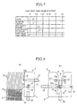
- Fig. 1 is a plan view showing a state where a main part of a tuck-in device built in a loom (shuttles loom) according to an embodiment of the invention;
- Fig. 2 is a side view of the main part (block body) of the tuck-in device of the invention;
- Fig. 3 is a block diagram of an airflow supply device of the tuck-in device of the invention;
- Fig. 4 is a timing diagram showing operations of constituent members of the tuck-in device relative to a main shaft rotary angle of the loom at the time of normal tuck-in operation;
- Fig. 5 is a timing diagram showing operations of constituent members of the tuck-in device relative to the main shaft rotary angle of the loom at the time of non tuck-in operation;
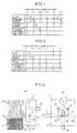
- Fig. 6(a) and Fig. 6 (b) are views explaining the main part (block body) of the tuck-in device according to the embodiment of the invention at the time of non tuck-in operation, wherein Fig. 6 (A) is a plan view and Fig. 6 (B) is a side view;
- Fig. 7 is a timing diagram showing operations of constituent members of the tuck-in device according to another embodiment of the invention relative to the main shaft rotary angle of the loom at the time of non tuck-in operation; and
- Fig. 8 is a view explaining the main part (block body) of the tuck-in device according to another embodiment of the invention, wherein Fig. 8 (A) is a plan view and Fig. 8 (B) is a side view.
-
- Figs. 1 and 2 show an embodiment where a tuck-in
device 2 of the invention is built in a loom (shuttleless loom) 1. The tuck-indevice 2 is disposed at a weaving end of a weft insertion or the weaving end of a weft arrival side. Further, a plurality of cloths are woven, the tuck-indevice 2 is also disposed between woven cloths. Fig. 1 shows the tuck-indevice 2 disposed only at the weft arrival side. The tuck-indevice 2 comprises a cutter 7 for cutting aweft 16, ablock body 3 disposed between the cutter 7 and awoven cloth end 31 of awoven cloth 5, and anairflow supply device 4 for supplying air to a grippingnozzle 12, a first tuck-innozzle 18 and a second tuck-innozzle 19 integrally provided in theblock body 3. Further, there is provided anejector 39, positioned opposite to theblock body 3 while intervening the cutter 7, for drawing a cut end of theweft 16 which was cut by the cutter 7. - The
block body 3 has aslit 9 which leaves open in three directions, namely, leaves open at a front side thereof opposite to areed 8, the cutter 7 side and thewoven cloth 5 side. Taperedguide surfaces 10 are positioned on an inner wall thereof at the front entrance thereof and they are gradually enlarged in a slit width toward thereed 8. Theslit 9 has agripping nozzle 12 on anupper wall 11 of its inner wall and anairflow entrance port 14 on alower wall 13 of its inner wall, and these grippingnozzle 12 andairflow entrance port 14 penetrate the inner wall of theslit 9 from upper and lower surfaces of theblock body 3 and oppose each other. Thegripping nozzle 12 is connected to theairflow supply device 4 through agripping pipe 15 and receives air from theairflow supply device 4 and injects it toward theairflow entrance port 14 when it operates. In this embodiment, although thegripping nozzle 12 is provided on theupper wall 11 and theairflow entrance port 14 is provided on thelower wall 13, theairflow entrance port 14 may be provided on theupper wall 11 and thegripping nozzle 12 may be provided on thelower wall 13. - Further, the
slit 9 has the first tuck-innozzle 18 on itsinnermost wall 17. Still further, two second tuck-innozzles 19 are provided up and down on the outer wall of theblock body 3 at thewoven cloth end 31 side while intervening theslit 9 therebetween. When viewing the two second tuck-innozzles 19 from thereed 8 side, the two second tuck-innozzles 19 penetrate theblock body 3 in a slanted manner while intervening theslit 9 therebetween, and the central lines of nozzle holes of the second tuck-innozzles 19 cross each other in ashedding 34 of awarp 33 if they are extended. - One first tuck-in
nozzle 18 and two second tuck-innozzles 19 are structured to receive air from theairflow supply device 4 through a first tuck-inpipe 26 and a second tuck-inpipe 27. - Fig. 3 shows an injection control system of the tuck-in
device 2. In Fig. 3, theairflow supply device 4 comprises apressure air source 20,pressure regulators closing valves closing valve controller 25. Thepressure air source 20 is connected to thegripping nozzle 12 via thepressure regulator 21 a, theclosing valve 22 and thegripping pipe 15. Air supplied from thepressure air source 20 is branched at thepressure regulator 21 b. Thepressure air source 20 is connected to the first tuck-innozzle 18 via thepressure regulator 21 b, theclosing valve 23 and the first tuck-inpipe 26, and also connected to the second tuck-innozzle 19 via thepressure regulator 21 b, theclosing valve 24, the second tuck-inpipe 27. Theclosing valve controller 25 opens and closes theclosing valves encoder 29 connected to amain shaft 28 of the loom based on an injection timing set by amain controller 35, and controls injection of air to be supplied to the grippingnozzle 12, the first tuck-innozzle 18 and the second tuck-innozzle 19. - The
main controller 35 performs control necessary for stopping a tuck-in operation in the manner of changing opening and closing control of theclosing valves weft detection sensor 36. Theweft detection sensor 36 is disposed on the side end of areed holder 38 for detecting theweft end 37 of theweft 16, and generating a weft stoppage signal at the time of defective picking, and supplying this weft stoppage signal to themain controller 35. - When picking, the
weft 16 is picked in theshedding 34 of thewarp 33 and theweft 16 is beaten by thereed 8 and is beaten in a cloth fell 6 of thewoven cloth 5. At this time, theweft 16 enters theslit 9 and it is cut by the cutter 7 at its tip. The cut weft end of theweft 16 is drawn by theejector 39 and subjected to a discard process. Thereafter, at the next picking time, the tuck-indevice 2 sequentially injects air through the grippingnozzle 12, the first tuck-innozzle 18, and the second tuck-innozzles 19, whereby a tuck-in operation is performed by an airflow produced at this time to fold back theweft end 37 of theweft 16 together with the airflow in theshedding 34 formed at the next picking time. - Fig. 4 is a timing diagram showing an air injection timing of respective nozzles relative to the main shaft rotary angle of the loom at the time of normal tuck-in operation. At the time of normal tuck-in operation, the gripping
nozzle 12 injects air toward theairflow entrance port 14 for a given period of time to form afirst airflow 30 so that theweft end 37 of theweft 16 cut by the cutter 7 is pulled in theairflow entrance port 14 inside theslit 9 and gripped at the locations of theslit 9 and theairflow entrance port 14. - Then, the first tuck-in
nozzle 18 injects air toward thereed 8 upon elapse of a given period of time from the start of injection by the gripping nozzle 12 (formation of the first airflow 30) to form anair flow 32a as a part of the air flow 32, while the second tuck-innozzle 19 injects air toward theshedding 34 of thewarp 33 upon elapse of a given period of time from the start of injection by the first tuck-in nozzle 18 (formation of theair flow 32a) to form anair flow 32b as a part of the air flow 32, thereby folding back theweft end 37 inside theshedding 34 of thewarp 33. In such a manner, the tuck-indevice 2 performs a tuck-in operation by folding back theweft end 37 inside theshedding 34 of thewarp 33. - The
first airflow 30 is not only formed by the airflow injected from thegripping nozzle 12 but also may be formed by an airflow drawn in the drawing pot of theairflow entrance port 14 and by a plurality of different airflows. - The air flow 32 is formed by only the airflow injected from the injection port and is not formed by the airflow drawn in the drawing port. The air flow 32 is preferable to be formed by the plurality of
airflows - Fig. 5 is a timing diagram showing air injection timings of respective nozzles relative to the main shaft rotary angle of the loom at the time of non tuck-in operation caused by the weft stoppage. When the
weft 16 does not reach theweft detection sensor 36 due to defective picking, for example, due to short picking, theweft detection sensor 36 can not detect theweft 16 so that it outputs a weft stoppage signal to themain controller 35 as a cause of the weft stoppage. Themain controller 35 outputs a valve opening inhibition signal of theclosing valves closing valve controller 25 upon reception of the weft stoppage signal. At this time, although theclosing valve controller 25 allows the grippingnozzle 12 to inject air, it keeps theclosing valves nozzle 18 and the second tuck-innozzle 19 to inject air. Further, the injection by thegripping nozzle 12 may last longer than that during the normal period of time, for example, it may continue or last, for example, until the completion of injection of air by the second tuck-innozzle 19 at the normal time. Meanwhile, the cutter 7 cuts theweft 16 inside theslit 9 after beating in the same manner as the normal picking time. - Figs. 6(a) and 6(b) show the behavior of the
weft 16 in theslit 9 of theblock body 3 at the time of non tuck-in operation. Theweft end 37 advanced inside theslit 9 by the beating of thereed 8 is cut by the cutter 7, then it is inserted in theairflow entrance port 14 by thefirst airflow 30 from the grippingnozzle 12, and thereafter pulled inside and gripped by theairflow entrance port 14. Thereafter, themain controller 35 stops the injection of air by the grippingnozzle 12. - In such a manner, the
closing valve controller 25 breaks off the opening of theclosing valve 23 of the first tuck-innozzle 18 and theclosing valve 24 of the second tuck-innozzle 19 in response to the instruction from the loom 1 based on the weft stoppage causing the stoppage of the loom 1, thereby not forming the air flow 32 (32a, 32b) so that theweft end 37 stays in theairflow entrance port 14 and hence it is not tucked in theshedding 34 of thewarp 33. Meanwhile, ever if thefirst airflow 30 from the grippingnozzle 12 is stopped, theweft end 37 is held in theairflow entrance port 14. - Although the non tuck-in operation is reliably performed by allowing both the
airflows airflows weft end 37 is not folded back in the shedding 34 by the other airflows (e.g., 32a) alone so that the entire air flow 32 is substantially rendered inoperative. Accordingly, "non-operation of the air flow 32 (32a, 32b)" has to be construed to include the case where the air flow 32 is formed of the plurality of airflows, the case where all the airflows are rendered inoperative and the case where only a part of the airflows is rendered inoperative. - Owing to the non tuck-in operation, after the loom 1 is stopped, an operator performs pick finding of the cloth fell 6 by rotating the loom 1 in reverse, thereby extracting a
defective weft 16, which is not tucked in the shedding 34, from the cloth fell 6 of thewoven cloth 5. - If a defective weft removing device is provided on a picking side, not shown, the defective weft removing device receives an instruction from an operator or an instruction from the loom 1, thereby taking the
defective weft 16 therein to automatically remove thedefective weft 16 from the cloth fell 6 of thewoven cloth 5. Thedefective weft 16 is displaced outside a cutting area by the airflow from an exclusive nozzle between a picking nozzle, not shown, and thewoven cloth 5 at the picking side, so as to facilitate the extraction of thedefective weft 16 or a cutter is rendered inoperative, and hence thedefective weft 16 remains to be connected to theweft 16 inside the picking nozzle. - Further, in this embodiment, the tuck-in
device 2 performs the injection of thefirst airflow 30 by the grippingnozzle 12, the injection of the air flow 32 (32a,32b) by the first and second tuck-innozzles - Fig. 7 is a timing diagram showing air injection timing of respective nozzles relative to a main shaft rotary angle of a loom at the time of non tuck-in operation according to another embodiment of the invention. A method of performing non tuck-in operation of a shuttleless loom according to the embodiment in Fig. 7 is characterized in that a
weft end 37 in aslit 9 is not folded back inside a shedding 34 of awarp 33 by injecting afirst airflow 30 from a grippingnozzle 12 during the injection of at least an air flow 32 (32a, 32b) by a first tuck-innozzle 18 and a second tuck-innozzle 19 in response to an instruction from a loom 1 based on a stoppage cause of a loom 1. - A
main controller 35 outputs a valve opening continuation signal to aclosing valve controller 25 upon reception of a weft stoppage signal, and the closingvalve controller 25 keeps the closingvalve 22 in the opening state during a period of time longer than a normal operation time, and injects thefirst airflow 30 from the grippingnozzle 12 during the injection of at least the air flow 32 (32a, 32b) by the first tuck-innozzle 18 and the second tuck-innozzle 19. Meanwhile, the opening of the closingvalve 23 of the first tuck-innozzle 18 and the opening of the closingvalve 24 of the second tuck-innozzle 19 are respectively performed for a period of time in the same manner as the normal tuck-in operation, thereby forming the air flow 32 (32a, 32b). - Fig .8 shows a behavior of a
weft 16 at aslit 9 of ablock body 3 at the time of non tuck-in operation in the embodiment shown in Fig. 7. Theweft end 37 which advanced in theslit 9 by the beating of thereed 8 is cut by the cutter 7, then it is inserted in anairflow entrance port 14 by thefirst airflow 30 from the grippingnozzle 12, and thereafter pulled in and griped by theairflow entrance port 14. Since the injection of thefirst airflow 30 from the grippingnozzle 12 continues until the completion of the injection of the air flow 32 (32a, 32b) from the first tuck-innozzle 18 and the second tuck-innozzle 19, theweft end 37 is pulled in and griped by thefirst airflow 30 and stays in theairflow entrance port 14, and it is not tucked in the shedding 34 of thewarp 33 even if the air flow 32 (32a, 32b) is formed. - At this time, the injecting pressure of the
first airflow 30 from the grippingnozzle 12 is increased compared with that at the normal time to prevent theweft end 37 from being tucked in the shedding 34 of thewarp 33 when theweft end 37 bows to the injection pressure of the air flow 32 (32a, 32b), or the injection pressure of air flow 32 (32a, 32b) is decreased so that theweft end 37 is allowed to stay in theairflow entrance port 14 with assurance to prevent theweft end 37 from being tucked in the shedding 34 of thewarp 33. Further, if the injection period of the air flow 32 (32a, 32b) is shortened, the continuous injection time of thefirst airflow 30 can be shortened, thereby preventing an air pressure of apressure air source 20 from being lowered temporarily. - Since the closing
valve controller 25 opens the closingvalve 22 of the grippingnozzle 12 during the opening of at lest the closingvalves nozzles weft end 37 stays in theairflow entrance port 14 and an operator rotates the loom 1 in reverse to perform the pick finding, thereby extracting thedefective weft 16, which is not tucked in the shedding 34 of thewarp 33, from the wovencloth 5 with ease. - In this embodiment, the operation to prevent the
weft end 37 from being tucked in the shedding 34 of thewarp 33 by the injection of the air flow 32 (32a, 32b) by keeping the gripping of theweft end 37 by thefirst airflow 30 is performed by taking over the operation state of thefirst airflow 30 at the normal time so that theweft end 37 is prevented from being tucked in the shedding 34 of thewarp 33 not owing to the delay of the operation of a control system because the operation itself is not changed. - The operation to prevent the
weft end 37 from being tucked in the shedding 34 of thewarp 33 by the injection of the air flow 32 (32a, 32b) while gripping theweft end 37 by thefirst airflow 30 does not always continue from the operation to pull in and grip theweft end 37 in theairflow entrance port 14. In the case where the injection of the air flow 32 (32a, 32b) starts while delayed from the completion of thefirst airflow 30 at the normal time or in the case where the injection of the air flow 32 (32a, 32b) is temporarily interrupted, the operation to prevent theweft end 37 from being tucked in the shedding 34 of thewarp 33 may be interrupted in the middle of the operation thereof. The manner of operation shown in Fig. 7 is a preferable example for continuing the formation of thefirst airflow 30 until the completion of the air flow 32 (32a, 32b). In this case, the operation to prevent theweft end 37 from being tucked in the shedding 34 of thewarp 33 by the injection of the air flow 32 while gripping theweft end 37 by thefirst airflow 30 is performed by taking over the operation state of a normal airflow, and the closingvalve 22 is not operated in the middle of the operation, and hence there is an advantage that theweft end 37 is prevented from being tucked in the shedding 34 of thewarp 33 not owing to the delay of the operation. - According to the first aspect of the invention, in the case where the defective weft is required to be extracted from the cloth fell of the woven cloth owing to the stoppage cause of the loom such as the weft stoppage and the like, the airflow to fold back the weft end is not injected in response to the instruction from the loom, so that the weft end is not tucked in the shedding of the warp, thereby removing the defective weft from the woven cloth with ease. Particularly, since (1) the operation per se for folding back the weft end in the shedding of the warp is rendered inoperative, there is no likelihood that the weft end is erroneously tucked in the shedding of the warp, (2) since the injection of airflow is made after the gripping of the weft, it is possible to cope with the instruction from the loom in good time, and (3) since the non- operation of injection of the airflow is performed by continuing the inoperative state of the injection, and the state of the injection is not changed during that period of time, so that the weft end is not tucked in the shedding 34 of the warp not owing to the delay of the changing operation, and hence the weft end is not reliably tucked in the shedding of the warp.
- According to the second aspect of the invention, when it is required to extract the defective weft from the cloth fell of the woven cloth owing to the stoppage cause of the loom such as the weft stoppage and the like, the state for gripping the weft end by the first airflow is effected during the injection of at least airflow, so that the weft end is not tucked in the shedding of the warp, thereby removing the defective weft from the woven cloth with ease. Particularly, the gripping operation for preventing the weft end from being tucked in the shedding of the warp by the injection of the airflow among the weft end gripping operations by the first airflow is made after the normal gripping operation by the first airflow, and hence it is possible to cope with the instruction from the loom in good time, thereby reliably preventing the weft end from being tucked in the shedding of the warp.
- According to the apparatus of the third aspect of the invention, it can reasonably realize the method of the first aspect of the invention, thereby obtaining the same effect as the method of the first aspect of the invention.
- According to the apparatus of the fourth aspect of the invention, it can reasonably realize the method of the second aspect of the invention, thereby obtaining the same effect as the method of the first aspect of the invention.
- According to the fifth aspect of the invention, since the slit, the gripping nozzle, the first tuck-in nozzle, and the second tuck-in nozzle are respectively disposed in the block body in a reasonable state, a normal tuck-in operation is sequentially effected by airflows, and also non tuck-in operation of the weft can be reliably executed when the first tuck-in nozzle and the second tuck-in nozzle are not operated.
- The features disclosed in the foregoing description, in the claims and/or in the accompanying drawings may, both separately and in any combination thereof, be material for realising the invention in diverse forms thereof.
Claims (5)
- A method of performing a tuck-in operation in a tuck-in device (2) of a shuttleless loom for folding back a weft end (37) of a picked weft (16) inside a shedding (34) of a warp (33) by injecting an air flow (32) after gripping the weft end (37) of the picked weft (16), said method comprising:allowing injection of the air flow (32) inoperative in response to an instruction from a loom (1) based on a stoppage cause of the loom (1) not to fold back the weft end (37) inside the shedding (34) of the warp (33).
- A method of performing a tuck-in operation in a tuck-in device (2) of a shuttleless loom for folding back a weft end (37) of a picked weft (16) inside a shedding (34) of a warp (33) by injecting an air flow (32) after pulling and gripping the weft end (37) of the picked weft (16) by a first airflow (30), said method comprising:injecting the first airflow (30) during the injection of at least the air flow (32) in response to an instruction from a loom (1) based on a stoppage cause of the loom (1) not to fold back the weft end (37) to the shedding (34) of the warp (33).
- A tuck-in device (2) of a shuttleless loom provided with one or more tuck-in nozzles (18, 19) and an airflow supply device (4):
wherein the airflow supply device (4) comprises a pressure air source (20), closing valves (23, 24) which open or close to permit or not permit the pressurized air in the pressure air source (20) to be supplied or not supplied from the pressure air source (20) to the tuck-in nozzles (18, 19), and a closing valve controller (25) for controlling the closing valves (23, 24);
wherein a weft end (37) of a picked weft (16) is folded back inside a shedding (34) of a warp (33) by injecting airflow from the tuck-in nozzles (18, 19) after the weft end (37) of the picked weft (16) is gripped; and
wherein the closing valve controller 25 stops the opening of at least one of the closing valves (23, 24) of the tuck-in nozzles (18, 19) in response to an instruction from a loom (1) based on the stoppage cause of the loom (1). - A tuck-in device (2) of a shuttleless loom provided with a gripping nozzle (12), tuck-in nozzles (18, 19) and an airflow supply device (4):
wherein the airflow supply device (4) comprises a pressure air source (20), closing valves (22, 23, 24) which open or close to permit or not permit the pressurized air in the pressure air source (20) to be supplied or not supplied from the pressure air source (20) to the gripping nozzle (12) and the tuck-in nozzles (18, 19), and a closing valve controller (25) for controlling the closing valves (22, 23, 24);
wherein a cut weft end (37) of a picked weft (16) is folded back inside a shedding (34) of a warp (33) by injecting airflow from the tuck-in nozzles (18, 19) after the cut weft end (37) of the picked weft (16) is pulled and gripped by air from the gripping nozzle (12) or by air drawn in the gripping nozzle (12); and
wherein the closing valve controller (25) opens the closing valve (22) of the gripping nozzle (12) during the opening of at least the closing valves (23, 24) of the tuck-in nozzles (18, 19) in response to an instruction from a loom (1) based on the stoppage cause of the loom (1). - A tuck-in device (2) of a shuttles loom provided with a block body (3) disposed close to a woven cloth end (31) positioned in an outside of a woven cloth (5), and a airflow supply device (4):
wherein the block body (3) has a slit (9) which leaves open in front thereof and is opposite to a reed (8) for receiving a weft end (37) of a picked weft (16) during a beating operation, and the slit (9) has a gripping nozzle (12) and an airflow entrance port (14) provided opposite to each other on an upper wall (11) and a lower wall (13) or vice verse, and a first tuck-in nozzle (18) provided on an innermost wall (17) of the slit (9) and a second tuck-in nozzle (19) provided at the woven cloth end (31);
wherein the airflow supply device (4) comprises a pressure air source (20), closing valves (22, 23, 24) which open or close to permit or not permit the pressurized air in the pressure air source (20) to be supplied or not supplied from the pressure air source (20) to a gripping nozzle (12), the first tuck-in nozzle (18) and the second tuck-in nozzle (19), and a closing valve controller (25) for controlling the closing valves (22, 23, 24);
wherein air is injected from the gripping nozzle (12) toward the airflow entrance port (14) during a given period of time at the time of normal tuck-in operation to form a first airflow (30), thereby pulling and holding the cut weft end (37), and air is injected from the first tuck-in nozzle (18) toward the reed (8) during a given period of time after the start of injection from the gripping nozzle (12), and air is injected from the second tuck-in nozzle (19) toward the shedding (34) of the warp (33) during a given period of time after the start of injection from the first tuck-in nozzle (18), thereby folding back the weft end (37) inside the shedding (34) of the warp (33); and
wherein the closing valve controller (25) stops to open at lest one of the closing valves (23, 24) of the first and second tuck-in nozzles (18, 19) in response to an instruction from a loom (1) based on a stoppage cause of the loom (1).
Applications Claiming Priority (2)
| Application Number | Priority Date | Filing Date | Title |
|---|---|---|---|
| JP2002290357A JP2004124302A (en) | 2002-10-02 | 2002-10-02 | Tack-in operation method and tuck-in device for shuttleless loom |
| JP2002290357 | 2002-10-02 |
Publications (2)
| Publication Number | Publication Date |
|---|---|
| EP1405942A1 true EP1405942A1 (en) | 2004-04-07 |
| EP1405942B1 EP1405942B1 (en) | 2010-10-27 |
Family
ID=31987172
Family Applications (1)
| Application Number | Title | Priority Date | Filing Date |
|---|---|---|---|
| EP03020622A Expired - Lifetime EP1405942B1 (en) | 2002-10-02 | 2003-09-10 | Method of tuck-in operation of a shuttleless loom and a tuck-in device |
Country Status (5)
| Country | Link |
|---|---|
| EP (1) | EP1405942B1 (en) |
| JP (1) | JP2004124302A (en) |
| CN (1) | CN1260415C (en) |
| AT (1) | ATE486162T1 (en) |
| DE (1) | DE60334666D1 (en) |
Cited By (3)
| Publication number | Priority date | Publication date | Assignee | Title |
|---|---|---|---|---|
| EP2330239A1 (en) * | 2009-11-30 | 2011-06-08 | Tsudakoma Kogyo Kabushiki Kaisha | Tuck-in method and tuck-in device for shuttleless loom |
| CN102618995A (en) * | 2012-04-20 | 2012-08-01 | 山东日发纺织机械有限公司 | Fabric edge treatment device of cord fabric air jet loom |
| CN107090650A (en) * | 2017-04-19 | 2017-08-25 | 张赓 | A kind of Weft search unit and its application method |
Families Citing this family (8)
| Publication number | Priority date | Publication date | Assignee | Title |
|---|---|---|---|---|
| BE1017684A3 (en) * | 2007-07-12 | 2009-03-03 | Picanol Nv | METHOD FOR INSERTING AN END OF A WELDING THREAD INTO A SIDE OF A TISSUE AND A PNEUMATIC EDGE INSERT. |
| JP2011122263A (en) * | 2009-12-10 | 2011-06-23 | Tsudakoma Corp | Tuck-in selvage-forming apparatus in loom for weaving woven fabric for rubber reinforcement |
| CN101967720A (en) * | 2010-10-11 | 2011-02-09 | 青岛天一集团红旗纺织机械有限公司 | Special pneumatic optical margin mechanism for jet loom |
| CN102286833B (en) * | 2011-08-09 | 2013-09-18 | 青岛铠硕纺机有限公司 | Jet loom for weaving medical gauze |
| DE102013207805A1 (en) * | 2013-04-29 | 2014-10-30 | Lindauer Dornier Gesellschaft Mit Beschränkter Haftung | Method for inserting weft thread ends on a weaving machine with additional weft effects |
| CN104562394B (en) * | 2014-12-30 | 2016-04-13 | 浙江理工大学 | The pure pneumatic Tucked-in selvage apparatus in a kind of shuttleless loom undercoat limit |
| CN105332148B (en) * | 2015-12-01 | 2017-08-01 | 安平县明信金属丝网制品有限公司 | The steel wire crimping unit supporting with rapier loom |
| CN111826784B (en) * | 2020-06-15 | 2021-11-23 | 苏州市天翱特种织绣有限公司 | Make up sled device that stops that floro weavingd |
Citations (5)
| Publication number | Priority date | Publication date | Assignee | Title |
|---|---|---|---|---|
| JPH03113051A (en) * | 1989-09-27 | 1991-05-14 | Toyota Autom Loom Works Ltd | Method and device for tucking is shuttleless loom |
| EP1087046A2 (en) * | 1999-09-21 | 2001-03-28 | Tsudakoma Kogyo Kabushiki Kaisha | Weft holding device for tuck-in device |
| EP1130145A1 (en) * | 2000-02-22 | 2001-09-05 | Tsudakoma Kogyo Kabushiki Kaisha | Method and apparatus for driving selvedge forming device in weaving machine |
| EP1174532A2 (en) * | 2000-07-21 | 2002-01-23 | Tsudakoma Kogyo Kabushiki Kaisha | Tuck-in apparatus |
| JP2002054053A (en) * | 2000-08-07 | 2002-02-19 | Tsudakoma Corp | Weft displacement device of loom |
-
2002
- 2002-10-02 JP JP2002290357A patent/JP2004124302A/en active Pending
-
2003
- 2003-09-10 EP EP03020622A patent/EP1405942B1/en not_active Expired - Lifetime
- 2003-09-10 AT AT03020622T patent/ATE486162T1/en not_active IP Right Cessation
- 2003-09-10 DE DE60334666T patent/DE60334666D1/en not_active Expired - Lifetime
- 2003-10-08 CN CN200310100601.1A patent/CN1260415C/en not_active Expired - Fee Related
Patent Citations (6)
| Publication number | Priority date | Publication date | Assignee | Title |
|---|---|---|---|---|
| JPH03113051A (en) * | 1989-09-27 | 1991-05-14 | Toyota Autom Loom Works Ltd | Method and device for tucking is shuttleless loom |
| EP1087046A2 (en) * | 1999-09-21 | 2001-03-28 | Tsudakoma Kogyo Kabushiki Kaisha | Weft holding device for tuck-in device |
| JP2001159053A (en) * | 1999-09-21 | 2001-06-12 | Tsudakoma Corp | Tack-in device weft holding device |
| EP1130145A1 (en) * | 2000-02-22 | 2001-09-05 | Tsudakoma Kogyo Kabushiki Kaisha | Method and apparatus for driving selvedge forming device in weaving machine |
| EP1174532A2 (en) * | 2000-07-21 | 2002-01-23 | Tsudakoma Kogyo Kabushiki Kaisha | Tuck-in apparatus |
| JP2002054053A (en) * | 2000-08-07 | 2002-02-19 | Tsudakoma Corp | Weft displacement device of loom |
Non-Patent Citations (2)
| Title |
|---|
| PATENT ABSTRACTS OF JAPAN vol. 015, no. 306 (C - 0856) 6 August 1991 (1991-08-06) * |
| PATENT ABSTRACTS OF JAPAN vol. 2002, no. 06 4 June 2002 (2002-06-04) * |
Cited By (4)
| Publication number | Priority date | Publication date | Assignee | Title |
|---|---|---|---|---|
| EP2330239A1 (en) * | 2009-11-30 | 2011-06-08 | Tsudakoma Kogyo Kabushiki Kaisha | Tuck-in method and tuck-in device for shuttleless loom |
| CN102618995A (en) * | 2012-04-20 | 2012-08-01 | 山东日发纺织机械有限公司 | Fabric edge treatment device of cord fabric air jet loom |
| CN107090650A (en) * | 2017-04-19 | 2017-08-25 | 张赓 | A kind of Weft search unit and its application method |
| CN107090650B (en) * | 2017-04-19 | 2018-09-14 | 张赓 | A kind of Weft search unit and its application method |
Also Published As
| Publication number | Publication date |
|---|---|
| ATE486162T1 (en) | 2010-11-15 |
| CN1497084A (en) | 2004-05-19 |
| JP2004124302A (en) | 2004-04-22 |
| CN1260415C (en) | 2006-06-21 |
| DE60334666D1 (en) | 2010-12-09 |
| EP1405942B1 (en) | 2010-10-27 |
Similar Documents
| Publication | Publication Date | Title |
|---|---|---|
| EP1405942B1 (en) | Method of tuck-in operation of a shuttleless loom and a tuck-in device | |
| US6705354B2 (en) | Method of forming tuck-in selvage in cloth | |
| JP3344714B2 (en) | Tack-in device weft holding device | |
| JP3513122B2 (en) | Tuck-in device | |
| US6129123A (en) | Method for correcting a weft fault on weaving machines, especially air-jet weaving machines with automatic selvedge tucking devices | |
| US5351721A (en) | Mispicked weft removing method | |
| JP3157779B2 (en) | Driving device of the tuft-restrictor | |
| KR20030084599A (en) | Method and Apparatus for Removing Defective Yarn in a Loom | |
| JP4056060B2 (en) | Tuck-in method | |
| JP3094636B2 (en) | Weaving method in jet loom | |
| JP2893111B2 (en) | Weft removal method for loom | |
| JP3560332B2 (en) | Defective yarn removing method and defective yarn removing device | |
| JP2001329453A (en) | Tack-in device weft relaxation device | |
| JP3635994B2 (en) | Weft processing method and apparatus in jet loom | |
| JP2623746B2 (en) | Weft treatment method in jet loom | |
| JP2530132B2 (en) | Bad yarn removing device for shuttleless loom | |
| JP2671518B2 (en) | Weft processing equipment in jet looms | |
| JP2002069801A (en) | Weft cutting method for removing defective yarn | |
| JP3458615B2 (en) | Weft treatment method in jet loom | |
| JP2679431B2 (en) | Weft system treatment method in jet loom | |
| JP2002054053A (en) | Weft displacement device of loom | |
| JPH06101139A (en) | Device for treating excess warp in jet room | |
| JPH03119153A (en) | Picking failure detector of air jet loom | |
| JPH07113183B2 (en) | Weft processing device for shuttleless loom | |
| JPS61113856A (en) | Weft yarn treatment apparatus of air jet type loom |
Legal Events
| Date | Code | Title | Description |
|---|---|---|---|
| PUAI | Public reference made under article 153(3) epc to a published international application that has entered the european phase |
Free format text: ORIGINAL CODE: 0009012 |
|
| AK | Designated contracting states |
Kind code of ref document: A1 Designated state(s): AT BE BG CH CY CZ DE DK EE ES FI FR GB GR HU IE IT LI LU MC NL PT RO SE SI SK TR |
|
| AX | Request for extension of the european patent |
Extension state: AL LT LV MK |
|
| 17P | Request for examination filed |
Effective date: 20040806 |
|
| AKX | Designation fees paid |
Designated state(s): AT BE BG CH CY CZ DE DK EE ES FI FR GB GR HU IE IT LI LU MC NL PT RO SE SI SK TR |
|
| 17Q | First examination report despatched |
Effective date: 20091204 |
|
| GRAP | Despatch of communication of intention to grant a patent |
Free format text: ORIGINAL CODE: EPIDOSNIGR1 |
|
| GRAS | Grant fee paid |
Free format text: ORIGINAL CODE: EPIDOSNIGR3 |
|
| GRAA | (expected) grant |
Free format text: ORIGINAL CODE: 0009210 |
|
| AK | Designated contracting states |
Kind code of ref document: B1 Designated state(s): AT BE BG CH CY CZ DE DK EE ES FI FR GB GR HU IE IT LI LU MC NL PT RO SE SI SK TR |
|
| REG | Reference to a national code |
Ref country code: GB Ref legal event code: FG4D |
|
| REG | Reference to a national code |
Ref country code: CH Ref legal event code: EP |
|
| REG | Reference to a national code |
Ref country code: IE Ref legal event code: FG4D |
|
| REF | Corresponds to: |
Ref document number: 60334666 Country of ref document: DE Date of ref document: 20101209 Kind code of ref document: P |
|
| REG | Reference to a national code |
Ref country code: NL Ref legal event code: VDEP Effective date: 20101027 |
|
| PG25 | Lapsed in a contracting state [announced via postgrant information from national office to epo] |
Ref country code: PT Free format text: LAPSE BECAUSE OF FAILURE TO SUBMIT A TRANSLATION OF THE DESCRIPTION OR TO PAY THE FEE WITHIN THE PRESCRIBED TIME-LIMIT Effective date: 20110228 Ref country code: BG Free format text: LAPSE BECAUSE OF FAILURE TO SUBMIT A TRANSLATION OF THE DESCRIPTION OR TO PAY THE FEE WITHIN THE PRESCRIBED TIME-LIMIT Effective date: 20110127 Ref country code: SE Free format text: LAPSE BECAUSE OF FAILURE TO SUBMIT A TRANSLATION OF THE DESCRIPTION OR TO PAY THE FEE WITHIN THE PRESCRIBED TIME-LIMIT Effective date: 20101027 Ref country code: SI Free format text: LAPSE BECAUSE OF FAILURE TO SUBMIT A TRANSLATION OF THE DESCRIPTION OR TO PAY THE FEE WITHIN THE PRESCRIBED TIME-LIMIT Effective date: 20101027 Ref country code: FI Free format text: LAPSE BECAUSE OF FAILURE TO SUBMIT A TRANSLATION OF THE DESCRIPTION OR TO PAY THE FEE WITHIN THE PRESCRIBED TIME-LIMIT Effective date: 20101027 Ref country code: AT Free format text: LAPSE BECAUSE OF FAILURE TO SUBMIT A TRANSLATION OF THE DESCRIPTION OR TO PAY THE FEE WITHIN THE PRESCRIBED TIME-LIMIT Effective date: 20101027 Ref country code: NL Free format text: LAPSE BECAUSE OF FAILURE TO SUBMIT A TRANSLATION OF THE DESCRIPTION OR TO PAY THE FEE WITHIN THE PRESCRIBED TIME-LIMIT Effective date: 20101027 |
|
| PG25 | Lapsed in a contracting state [announced via postgrant information from national office to epo] |
Ref country code: GR Free format text: LAPSE BECAUSE OF FAILURE TO SUBMIT A TRANSLATION OF THE DESCRIPTION OR TO PAY THE FEE WITHIN THE PRESCRIBED TIME-LIMIT Effective date: 20110128 Ref country code: BE Free format text: LAPSE BECAUSE OF FAILURE TO SUBMIT A TRANSLATION OF THE DESCRIPTION OR TO PAY THE FEE WITHIN THE PRESCRIBED TIME-LIMIT Effective date: 20101027 |
|
| PG25 | Lapsed in a contracting state [announced via postgrant information from national office to epo] |
Ref country code: ES Free format text: LAPSE BECAUSE OF FAILURE TO SUBMIT A TRANSLATION OF THE DESCRIPTION OR TO PAY THE FEE WITHIN THE PRESCRIBED TIME-LIMIT Effective date: 20110207 Ref country code: EE Free format text: LAPSE BECAUSE OF FAILURE TO SUBMIT A TRANSLATION OF THE DESCRIPTION OR TO PAY THE FEE WITHIN THE PRESCRIBED TIME-LIMIT Effective date: 20101027 Ref country code: CZ Free format text: LAPSE BECAUSE OF FAILURE TO SUBMIT A TRANSLATION OF THE DESCRIPTION OR TO PAY THE FEE WITHIN THE PRESCRIBED TIME-LIMIT Effective date: 20101027 |
|
| PG25 | Lapsed in a contracting state [announced via postgrant information from national office to epo] |
Ref country code: RO Free format text: LAPSE BECAUSE OF FAILURE TO SUBMIT A TRANSLATION OF THE DESCRIPTION OR TO PAY THE FEE WITHIN THE PRESCRIBED TIME-LIMIT Effective date: 20101027 Ref country code: DK Free format text: LAPSE BECAUSE OF FAILURE TO SUBMIT A TRANSLATION OF THE DESCRIPTION OR TO PAY THE FEE WITHIN THE PRESCRIBED TIME-LIMIT Effective date: 20101027 Ref country code: SK Free format text: LAPSE BECAUSE OF FAILURE TO SUBMIT A TRANSLATION OF THE DESCRIPTION OR TO PAY THE FEE WITHIN THE PRESCRIBED TIME-LIMIT Effective date: 20101027 |
|
| PLBE | No opposition filed within time limit |
Free format text: ORIGINAL CODE: 0009261 |
|
| STAA | Information on the status of an ep patent application or granted ep patent |
Free format text: STATUS: NO OPPOSITION FILED WITHIN TIME LIMIT |
|
| 26N | No opposition filed |
Effective date: 20110728 |
|
| REG | Reference to a national code |
Ref country code: DE Ref legal event code: R097 Ref document number: 60334666 Country of ref document: DE Effective date: 20110728 |
|
| PG25 | Lapsed in a contracting state [announced via postgrant information from national office to epo] |
Ref country code: MC Free format text: LAPSE BECAUSE OF NON-PAYMENT OF DUE FEES Effective date: 20110930 |
|
| REG | Reference to a national code |
Ref country code: CH Ref legal event code: PL |
|
| GBPC | Gb: european patent ceased through non-payment of renewal fee |
Effective date: 20110910 |
|
| REG | Reference to a national code |
Ref country code: IE Ref legal event code: MM4A |
|
| REG | Reference to a national code |
Ref country code: FR Ref legal event code: ST Effective date: 20120531 |
|
| PG25 | Lapsed in a contracting state [announced via postgrant information from national office to epo] |
Ref country code: CH Free format text: LAPSE BECAUSE OF NON-PAYMENT OF DUE FEES Effective date: 20110930 Ref country code: IE Free format text: LAPSE BECAUSE OF NON-PAYMENT OF DUE FEES Effective date: 20110910 Ref country code: LI Free format text: LAPSE BECAUSE OF NON-PAYMENT OF DUE FEES Effective date: 20110930 |
|
| PG25 | Lapsed in a contracting state [announced via postgrant information from national office to epo] |
Ref country code: GB Free format text: LAPSE BECAUSE OF NON-PAYMENT OF DUE FEES Effective date: 20110910 Ref country code: FR Free format text: LAPSE BECAUSE OF NON-PAYMENT OF DUE FEES Effective date: 20110930 |
|
| PG25 | Lapsed in a contracting state [announced via postgrant information from national office to epo] |
Ref country code: CY Free format text: LAPSE BECAUSE OF EXPIRATION OF PROTECTION Effective date: 20101027 Ref country code: LU Free format text: LAPSE BECAUSE OF NON-PAYMENT OF DUE FEES Effective date: 20110910 |
|
| PG25 | Lapsed in a contracting state [announced via postgrant information from national office to epo] |
Ref country code: TR Free format text: LAPSE BECAUSE OF FAILURE TO SUBMIT A TRANSLATION OF THE DESCRIPTION OR TO PAY THE FEE WITHIN THE PRESCRIBED TIME-LIMIT Effective date: 20101027 |
|
| PG25 | Lapsed in a contracting state [announced via postgrant information from national office to epo] |
Ref country code: HU Free format text: LAPSE BECAUSE OF FAILURE TO SUBMIT A TRANSLATION OF THE DESCRIPTION OR TO PAY THE FEE WITHIN THE PRESCRIBED TIME-LIMIT Effective date: 20101027 |
|
| PGFP | Annual fee paid to national office [announced via postgrant information from national office to epo] |
Ref country code: DE Payment date: 20140903 Year of fee payment: 12 |
|
| PGFP | Annual fee paid to national office [announced via postgrant information from national office to epo] |
Ref country code: IT Payment date: 20140911 Year of fee payment: 12 |
|
| REG | Reference to a national code |
Ref country code: DE Ref legal event code: R119 Ref document number: 60334666 Country of ref document: DE |
|
| PG25 | Lapsed in a contracting state [announced via postgrant information from national office to epo] |
Ref country code: IT Free format text: LAPSE BECAUSE OF NON-PAYMENT OF DUE FEES Effective date: 20150910 |
|
| PG25 | Lapsed in a contracting state [announced via postgrant information from national office to epo] |
Ref country code: DE Free format text: LAPSE BECAUSE OF NON-PAYMENT OF DUE FEES Effective date: 20160401 |