EP1405815A1 - Elevator hoist - Google Patents
Elevator hoist Download PDFInfo
- Publication number
- EP1405815A1 EP1405815A1 EP01947962A EP01947962A EP1405815A1 EP 1405815 A1 EP1405815 A1 EP 1405815A1 EP 01947962 A EP01947962 A EP 01947962A EP 01947962 A EP01947962 A EP 01947962A EP 1405815 A1 EP1405815 A1 EP 1405815A1
- Authority
- EP
- European Patent Office
- Prior art keywords
- support plate
- brake
- opening
- case
- brake support
- Prior art date
- Legal status (The legal status is an assumption and is not a legal conclusion. Google has not performed a legal analysis and makes no representation as to the accuracy of the status listed.)
- Withdrawn
Links
Images





Classifications
-
- F—MECHANICAL ENGINEERING; LIGHTING; HEATING; WEAPONS; BLASTING
- F16—ENGINEERING ELEMENTS AND UNITS; GENERAL MEASURES FOR PRODUCING AND MAINTAINING EFFECTIVE FUNCTIONING OF MACHINES OR INSTALLATIONS; THERMAL INSULATION IN GENERAL
- F16D—COUPLINGS FOR TRANSMITTING ROTATION; CLUTCHES; BRAKES
- F16D51/00—Brakes with outwardly-movable braking members co-operating with the inner surface of a drum or the like
- F16D51/16—Brakes with outwardly-movable braking members co-operating with the inner surface of a drum or the like shaped as brake-shoes pivoted on a fixed or nearly-fixed axis
- F16D51/18—Brakes with outwardly-movable braking members co-operating with the inner surface of a drum or the like shaped as brake-shoes pivoted on a fixed or nearly-fixed axis with two brake-shoes
-
- B—PERFORMING OPERATIONS; TRANSPORTING
- B66—HOISTING; LIFTING; HAULING
- B66B—ELEVATORS; ESCALATORS OR MOVING WALKWAYS
- B66B11/00—Main component parts of lifts in, or associated with, buildings or other structures
- B66B11/04—Driving gear ; Details thereof, e.g. seals
-
- B—PERFORMING OPERATIONS; TRANSPORTING
- B66—HOISTING; LIFTING; HAULING
- B66B—ELEVATORS; ESCALATORS OR MOVING WALKWAYS
- B66B11/00—Main component parts of lifts in, or associated with, buildings or other structures
- B66B11/04—Driving gear ; Details thereof, e.g. seals
- B66B11/043—Driving gear ; Details thereof, e.g. seals actuated by rotating motor; Details, e.g. ventilation
- B66B11/0438—Driving gear ; Details thereof, e.g. seals actuated by rotating motor; Details, e.g. ventilation with a gearless driving, e.g. integrated sheave, drum or winch in the stator or rotor of the cage motor
-
- F—MECHANICAL ENGINEERING; LIGHTING; HEATING; WEAPONS; BLASTING
- F16—ENGINEERING ELEMENTS AND UNITS; GENERAL MEASURES FOR PRODUCING AND MAINTAINING EFFECTIVE FUNCTIONING OF MACHINES OR INSTALLATIONS; THERMAL INSULATION IN GENERAL
- F16D—COUPLINGS FOR TRANSMITTING ROTATION; CLUTCHES; BRAKES
- F16D65/00—Parts or details
- F16D65/02—Braking members; Mounting thereof
- F16D65/04—Bands, shoes or pads; Pivots or supporting members therefor
- F16D65/08—Bands, shoes or pads; Pivots or supporting members therefor for internally-engaging brakes
- F16D65/09—Pivots or supporting members therefor
-
- F—MECHANICAL ENGINEERING; LIGHTING; HEATING; WEAPONS; BLASTING
- F16—ENGINEERING ELEMENTS AND UNITS; GENERAL MEASURES FOR PRODUCING AND MAINTAINING EFFECTIVE FUNCTIONING OF MACHINES OR INSTALLATIONS; THERMAL INSULATION IN GENERAL
- F16D—COUPLINGS FOR TRANSMITTING ROTATION; CLUTCHES; BRAKES
- F16D2121/00—Type of actuator operation force
- F16D2121/18—Electric or magnetic
- F16D2121/20—Electric or magnetic using electromagnets
- F16D2121/22—Electric or magnetic using electromagnets for releasing a normally applied brake
Definitions
- This invention relates to an elevator hoist having a drive sheave portion around which a main rope is wrapped, a drive motor for rotating the drive sheave portion, and a brake device for braking the rotation of the drive sheave portion.
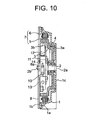
- Fig. 9 is a front view showing a conventional elevator hoist disclosed, for example, in Japanese Patent Application Laid-open No. 2000-289954, and Fig. 10 is a side view, partially in section, showing the inner structure of the hoist of Fig. 9.
- a metal case 1 has a cylindrical portion 1a, an opening 1b provided at one axial end of the cylindrical portion, and a bottom portion 1c provided at the other axial end of the cylindrical portion 1a.
- a main shaft 2 extending in the axial direction of the cylindrical portion 1a (from side to side in Fig. 10) is supported.
- the case 1 contains a rotating body 3 rotatable around the main shaft 2.
- the rotating body 3 has a drive sheave portion 3a and a cylindrical drum portion 3b formed integrally with the drive sheave portion 3a.
- a plurality of main ropes 4 are wrapped around the outer peripheral portion of the drive sheave portion 3a.
- An armature 5 is mounted on the outer peripheral surface of the drum portion 3b. Fixed to the inner peripheral surface of the cylindrical portion 1a is a stator winding 6 opposed to the armature 5.
- a driving motor 7 for rotating the rotating member 3 has the armature 5 and the stator winding 6.
- Mounted on the main shaft 2 is an encoder 15 for detecting the rotating speed of the rotating body 3.
- a brake support plate 8 is mounted to one end portion of the cylindrical portion 1a.
- the brake support plate 8 is equipped with a support hole 8a into which the other end portion 2b of the main shaft 2 is inserted. Further, mounted on the brake support plate 8 is a brake device 10 for braking the rotation of the rotating body 3.
- the brake device 10 has a pair of rockable brake arms 11, a pair of brake shoes 12 mounted on the brake arms 11 and adapted to move toward and away from the inner peripheral surface of the drum portion 3b by the rocking of the brake arms 11, a pair of springs 13 for urging the brake arms 11 in such a direction that the brake shoes 12 may come into contact with the drum portion 3b, and a pair of electromagnet mechanisms 14 for causing the brake arms 11 to rock in such a direction that the brake shoes 12 may be separated from the drum portion 3b against the force of the springs 13.
- the driving motor 7, the brake device 10, etc. are exposed through the opening 1b of the case 1, so that foreign matter, such as water, oil, or dust, adheres to the driving motor 7, the brake device 10, etc., resulting in the fear of deterioration in the insulating portion, a reduction in the braking force, and damage to the apparatus.
- Japanese Patent Application Laid-open No. Hei 8-40675 discloses an elevator in which the hoist is arranged in the lower portion of the hoistway. In such an elevator, it is highly possible for dust, water drops, etc. falling from the upper portion of the hoistway to enter the case 1 through the opening 1b.
- This invention has been made with a view toward solving the above problems. It is an object of this invention to provide an elevator hoist which can prevent intrusion of foreign matter into the case and which allows more accurate positioning of the support hole with respect to the cylindrical portion of the case.
- an elevator hoist comprising: a case having a cylindrical portion, an opening provided at one axial end of the cylindrical portion, and a bottom portion provided at the other axial end of the cylindrical portion; a main shaft whose one end is supported by the bottom portion and which extends along the axial direction of the cylindrical portion; a rotating body which is contained in the case, which has a drive sheave portion around which a main rope is wrapped and a cylindrical drum portion, and which is rotatable around the main shaft; a driving motor provided between the case and the rotating body and adapted to rotate the rotating body; a brake support plate attached to one end portion of the cylindrical portion and having a support hole into which the other end portion of the main shaft is inserted; and a brake device mounted on the brake support plate and adapted to brake rotation of the rotating body, wherein the brake support plate also serves as a cover for closing the entire opening, the brake support plate is provided with a step portion to be fit-engaged with the peripheral edge portion of
- Fig. 1 is a front view of an elevator hoist according to Embodiment 1 of this invention
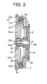
- Fig. 2 is a sectional view taken along the line II-II of Fig. 1.
- a metal case 1 has a cylindrical portion 1a, an opening 1b provided at one axial end of the cylindrical portion, and a bottom portion 1c provided at the other axial end of the cylindrical portion 1a.
- a main shaft 2 extending in the axial direction of the cylindrical portion 1a (from side to side in Fig. 2) is supported.
- the case 1 contains a rotating body 3 rotatable around the main shaft 2.
- the rotating body 3 has a drive sheave portion 3a and a cylindrical drum portion 3b formed integrally with the drive sheave portion 3a.
- a plurality of main ropes 4 are wrapped around the outer peripheral portion of the drive sheave portion 3a.
- An armature 5 is mounted on the outer peripheral surface of the drum portion 3b. Fixed to the inner peripheral surface of the cylindrical portion 1a is a stator winding 6 opposed to the armature 5.
- a driving motor 7 for rotating the rotating member 3 has the armature 5 and the stator winding 6.
- Mounted on the main shaft 2 is an encoder 15 for detecting the rotating speed of the rotating body 3.
- a brake support plate 21 is mounted to one end portion of the cylindrical portion 1a by means of a plurality of bolts 20.
- the brake support plate 21 is equipped with a circular support hole 21a into which the other end portion 2b of the main shaft 2 is inserted. Further, mounted on the brake support plate 21 is a brake device 22 for braking the rotation of the rotating body 3.
- the brake device 22 has a pair of rockable brake arms 23, a pair of brake shoes 24 mounted on the brake arms 23 and adapted to move toward and away from the inner peripheral surface of the drum portion 3b by the rocking of the brake arms 23, a pair of springs 25 for urging the brake arms 23 in such a direction that the brake shoes 24 may come into contact with the drum portion 3b, and a pair of electromagnet mechanisms 26 for causing the brake arms 23 to rock in such a direction that the brake shoes 24 may be separated from the drum portion 3b against the force of the springs 25.
- the brake support plate 21 also serves as a cover closing the entire opening 1b.
- the brake support plate 21 is equipped with a step portion 21b to be fit-engaged with the peripheral edge portion of the opening 1b.
- the step portion 21b is provided so as to extend along the entire circumference of a circle whose center is the support hole 21a. That is, the step portion 21b is provided so as to extend along a concentric circle of the support hole 12a.
- an arm support portion 21c supporting the brake arm 23 and protrusions 21d and 21e to which a spring 25 and an electromagnet mechanism 26 are mounted. Between the protrusions 21d and 21e, there is secured a place 27 for arranging the encoder 15.
- Fig. 3 is an enlarged view showing a main portion of Fig. 2.
- a groove 21f so as to surround the entire periphery of the opening 1b.
- An O-ring 28 as an elastic member is inserted into the groove 21f.
- the depth of the groove 21f is smaller than the section diameter of the O-ring 28.
- the brake support plate 21 closes the entire opening 1b, so that even when it is arranged in the lower portion of a hoistway, intrusion of foreign matter into the case 1 is prevented, making it possible to prevent deterioration in insulation and deterioration in the performance of the apparatus.
- step portion 21b fit-engaged with the opening 1b and the support hole 21a supporting the other end portion 2b of the main shaft 2 are provided in the brake support plate 21, and constitute concentric circles, so that it is possible to perform positioning on the support hole 21a more accurately with respect to the cylindrical portion 1a. That is, by positioning the support hole 21a at the center of the circular step portion 21b and fitting the step portion 21b into the opening 1b, it is possible to easily arrange the support hole 21a at the center of the cylindrical portion 1a, making it possible to easily perform centering on the main shaft 2.
- step portions 21b prefferably be provided as arcuate parts extending along a circumference having the support hole 21a as its center.
- the groove 21f is provided in the brake support plate 21, it is also possible to provide the groove in the end surface of the cylindrical portion of the case. Further, it is also possible to provide a groove in both the brake support plate and the case.
- Fig. 4 is a front view, partially broken away, showing an elevator hoist according to Embodiment 2 of this invention.
- the brake support plate 21 is provided with a pair of inspection openings 21g for performing inspection on the brake device 22, and a pair of inspection covers 31 for opening and closing the inspection openings 21g are mounted thereto.
- step portions 21h are provided in the peripheral edge portions of the inspection openings 21g so that the surfaces of the inspection covers 31 may be flush with the surface of the brake support plate 21.
- the inspection covers 31 are mounted to the brake support plate 21 by a plurality of screws 32. Otherwise, this embodiment is of the same construction as Embodiment 1.
- the inspection covers 31 are removed at the time of inspection of the brake device 22, and the inspection openings 21g are opened, whereby it is possible to easily perform inspections of the brake device 22 without removing the brake support plate 21 from the case 1, thereby facilitating inspection of the brake device 22, reducing the operation time, and achieving an improvement in operability.
- the inspection covers 31 do not protrude beyond the surface of the brake support plate 21, making it possible to install the hoist in a small hoistway.
- Fig. 5 is a front view of an elevator hoist according to Embodiment 3 of this invention
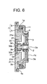
- Fig. 6 is a sectional view taken along the line VI-VI of Fig. 5.
- the brake support plate 21 is provided with a central opening 21i for attaching and detaching the encoder 15 with respect to the main shaft 2, and a central cover 33 for opening and closing the central opening 21i is mounted thereto.
- the central cover 33 is provided with a cover recess 33a. At the bottom of the cover recess 33a, there is provided a support hole 33b for supporting the other end portion 2b of the main shaft 2. Mounted to the central cover 33 is a lid 34 for closing the opening of the cover recess 33a. The surface of the central cover 33 and the surface of the lid 34 are flush with the surface of the brake support plate 21. otherwise, this embodiment is of the same construction as Embodiment 2.
- Fig. 7 is a front view of an elevator hoist according to Embodiment 4 of this invention
- Fig. 8 is a sectional view taken along the line VIII-VIII of Fig. 7.
- the brake support plate 21 is provided with a groove portion 21j into which a plurality of electric wires 35 led out of the case 1 are inserted.
- the electric wires 35 are connected to the stator winding 6 and the electromagnet of the electromagnet mechanism 26.
- a cylindrical protecting member (buffer member) 36 Arranged in the groove portion 21j is a cylindrical protecting member (buffer member) 36 capable of undergoing elastic deformation and adapted to protect the electric wires 35 while filling the gap between the groove portion 21j and the electric wires 35.
- the protecting member 36 is formed, for example, of foam polystyrene or rubber. otherwise, this embodiment is of the same construction as Embodiment 3.
- the groove portion 21j is provided in the brake support plate 21, so that it is possible to lead the electric wires 35 to the exterior of the case 1 by means of a simple structure. Further, since the protecting member 36 is arranged in the groove portion 21j, damage to the electric wires 35 can be prevented.
Landscapes
- Engineering & Computer Science (AREA)
- General Engineering & Computer Science (AREA)
- Mechanical Engineering (AREA)
- Civil Engineering (AREA)
- Structural Engineering (AREA)
- Cage And Drive Apparatuses For Elevators (AREA)
Abstract
In an elevator hoist, one end portion of a main shaft is supported
by the bottom portion of a case. The other end portion of the main
shaft is supported by a brake support plate supporting a brake device.
The brake support plate is provided with a support hole into which
the other end portion of the main shaft is inserted. The brake support
plate also serves as a cover for closing the entire opening of the
case. The brake support plate is provided with a step portion to
be fit-engaged with the peripheral edge portion of the opening.
The step portion is provided so as to extend at least a part of
a circumference having the support hole as its center.
Description
This invention relates to an elevator hoist having a drive
sheave portion around which a main rope is wrapped, a drive motor
for rotating the drive sheave portion, and a brake device for braking
the rotation of the drive sheave portion.
Fig. 9 is a front view showing a conventional elevator hoist
disclosed, for example, in Japanese Patent Application Laid-open
No. 2000-289954, and Fig. 10 is a side view, partially in section,
showing the inner structure of the hoist of Fig. 9.
In the drawings, a metal case 1 has a cylindrical portion 1a,
an opening 1b provided at one axial end of the cylindrical portion,
and a bottom portion 1c provided at the other axial end of the
cylindrical portion 1a. At the bottom portion 1c, one end portion
2a of a main shaft 2 extending in the axial direction of the cylindrical
portion 1a (from side to side in Fig. 10) is supported.
The case 1 contains a rotating body 3 rotatable around the
main shaft 2. The rotating body 3 has a drive sheave portion 3a
and a cylindrical drum portion 3b formed integrally with the drive
sheave portion 3a. A plurality of main ropes 4 are wrapped around
the outer peripheral portion of the drive sheave portion 3a.
An armature 5 is mounted on the outer peripheral surface of
the drum portion 3b. Fixed to the inner peripheral surface of the
cylindrical portion 1a is a stator winding 6 opposed to the armature
5. A driving motor 7 for rotating the rotating member 3 has the
armature 5 and the stator winding 6. Mounted on the main shaft 2
is an encoder 15 for detecting the rotating speed of the rotating
body 3.
A brake support plate 8 is mounted to one end portion of the
cylindrical portion 1a. The brake support plate 8 is equipped with
a support hole 8a into which the other end portion 2b of the main
shaft 2 is inserted. Further, mounted on the brake support plate
8 is a brake device 10 for braking the rotation of the rotating
body 3.
The brake device 10 has a pair of rockable brake arms 11, a
pair of brake shoes 12 mounted on the brake arms 11 and adapted
to move toward and away from the inner peripheral surface of the
drum portion 3b by the rocking of the brake arms 11, a pair of springs
13 for urging the brake arms 11 in such a direction that the brake
shoes 12 may come into contact with the drum portion 3b, and a pair
of electromagnet mechanisms 14 for causing the brake arms 11 to
rock in such a direction that the brake shoes 12 may be separated
from the drum portion 3b against the force of the springs 13.
In the conventional elevator hoist described above, the driving
motor 7, the brake device 10, etc. are exposed through the opening
1b of the case 1, so that foreign matter, such as water, oil, or
dust, adheres to the driving motor 7, the brake device 10, etc.,
resulting in the fear of deterioration in the insulating portion,
a reduction in the braking force, and damage to the apparatus.
As an example of the problem, Japanese Patent Application
Laid-open No. Hei 8-40675 discloses an elevator in which the hoist
is arranged in the lower portion of the hoistway. In such an elevator,
it is highly possible for dust, water drops, etc. falling from the
upper portion of the hoistway to enter the case 1 through the opening
1b.
Further, while one end portion 2a of themain shaft 2 is supported
by the bottom portion 1c of the case 1, the other end portion 2b
of the main shaft 2 is inserted into a support hole 8a of the brake
support plate 8, so that it is rather difficult to line up the support
hole 8a with the center of the cylindrical portion 1a.
Further, when the encoder 15 is out of order, it is necessary
to detach the brake support plate 8 from the case 1; since the brake
device 10 is mounted on the brake support plate 8, it is necessary
to adjust the way the brake shoes 12 come into contact with the
drum portion 3b after re-attaching the brake support plate 8 to
the case 1, resulting in a rather low operational efficiency.
This invention has been made with a view toward solving the
above problems. It is an object of this invention to provide an
elevator hoist which can prevent intrusion of foreign matter into
the case and which allows more accurate positioning of the support
hole with respect to the cylindrical portion of the case.
To this end, according to one aspect of the present invention,
there is provided an elevator hoist comprising: a case having a
cylindrical portion, an opening provided at one axial end of the
cylindrical portion, and a bottom portion provided at the other
axial end of the cylindrical portion; a main shaft whose one end
is supported by the bottom portion and which extends along the axial
direction of the cylindrical portion; a rotating body which is
contained in the case, which has a drive sheave portion around which
a main rope is wrapped and a cylindrical drum portion, and which
is rotatable around the main shaft; a driving motor provided between
the case and the rotating body and adapted to rotate the rotating
body; a brake support plate attached to one end portion of the
cylindrical portion and having a support hole into which the other
end portion of the main shaft is inserted; and a brake device mounted
on the brake support plate and adapted to brake rotation of the
rotating body, wherein the brake support plate also serves as a
cover for closing the entire opening, the brake support plate is
provided with a step portion to be fit-engaged with the peripheral
edge portion of the opening, and the step portion is provided so
as to extend along at least a part of a circumference having the
support hole as its center.
Preferred embodiments of this invention will now be described
with reference to the drawings.
Fig. 1 is a front view of an elevator hoist according to
Embodiment 1 of this invention, and Fig. 2 is a sectional view taken
along the line II-II of Fig. 1.
In the drawings, a metal case 1 has a cylindrical portion 1a,
an opening 1b provided at one axial end of the cylindrical portion,
and a bottom portion 1c provided at the other axial end of the
cylindrical portion 1a. At the bottom portion 1c, one end portion
2a of a main shaft 2 extending in the axial direction of the cylindrical
portion 1a (from side to side in Fig. 2) is supported.
The case 1 contains a rotating body 3 rotatable around the
main shaft 2. The rotating body 3 has a drive sheave portion 3a
and a cylindrical drum portion 3b formed integrally with the drive
sheave portion 3a. A plurality of main ropes 4 are wrapped around
the outer peripheral portion of the drive sheave portion 3a.
An armature 5 is mounted on the outer peripheral surface of
the drum portion 3b. Fixed to the inner peripheral surface of the
cylindrical portion 1a is a stator winding 6 opposed to the armature
5. A driving motor 7 for rotating the rotating member 3 has the
armature 5 and the stator winding 6. Mounted on the main shaft 2
is an encoder 15 for detecting the rotating speed of the rotating
body 3.
A brake support plate 21 is mounted to one end portion of the
cylindrical portion 1a by means of a plurality of bolts 20. The
brake support plate 21 is equipped with a circular support hole
21a into which the other end portion 2b of the main shaft 2 is inserted.
Further, mounted on the brake support plate 21 is a brake device
22 for braking the rotation of the rotating body 3.
The brake device 22 has a pair of rockable brake arms 23, a
pair of brake shoes 24 mounted on the brake arms 23 and adapted
to move toward and away from the inner peripheral surface of the
drum portion 3b by the rocking of the brake arms 23, a pair of springs
25 for urging the brake arms 23 in such a direction that the brake
shoes 24 may come into contact with the drum portion 3b, and a pair
of electromagnet mechanisms 26 for causing the brake arms 23 to
rock in such a direction that the brake shoes 24 may be separated
from the drum portion 3b against the force of the springs 25.
Further, the brake support plate 21 also serves as a cover
closing the entire opening 1b. The brake support plate 21 is equipped
with a step portion 21b to be fit-engaged with the peripheral edge
portion of the opening 1b. The step portion 21b is provided so as
to extend along the entire circumference of a circle whose center
is the support hole 21a. That is, the step portion 21b is provided
so as to extend along a concentric circle of the support hole 12a.
Further, formed on the back surface of the brake support plate
21 (the surface opposed to the rotating body 3) are an arm support
portion 21c supporting the brake arm 23 and protrusions 21d and
21e to which a spring 25 and an electromagnet mechanism 26 are mounted.
Between the protrusions 21d and 21e, there is secured a place 27
for arranging the encoder 15.
Fig. 3 is an enlarged view showing a main portion of Fig. 2.
In the surface of the brake support plate 21 held in contact with
the end surface of the case 1, there is provided a groove 21f so
as to surround the entire periphery of the opening 1b. An O-ring
28 as an elastic member is inserted into the groove 21f. The depth
of the groove 21f is smaller than the section diameter of the O-ring
28. Thus, when the brake support plate 21 is mounted to the case
1, the O-ring 28 is brought into press contact with the inner wall
surface of the groove 21f and the end surface of the cylindrical
portion 1a.
In this elevator hoist, the brake support plate 21 closes the
entire opening 1b, so that even when it is arranged in the lower
portion of a hoistway, intrusion of foreign matter into the case
1 is prevented, making it possible to prevent deterioration in
insulation and deterioration in the performance of the apparatus.
Further, the step portion 21b fit-engaged with the opening
1b and the support hole 21a supporting the other end portion 2b
of the main shaft 2 are provided in the brake support plate 21,
and constitute concentric circles, so that it is possible to perform
positioning on the support hole 21a more accurately with respect
to the cylindrical portion 1a. That is, by positioning the support
hole 21a at the center of the circular step portion 21b and fitting
the step portion 21b into the opening 1b, it is possible to easily
arrange the support hole 21a at the center of the cylindrical portion
1a, making it possible to easily perform centering on the main shaft
2.
Further, since the O-ring 28 exists between the case 1 and
the brake support plate 21, it is possible to more reliably prevent
intrusion of oil, water drops or the like into the case 1.
It is also possible for the step portions 21b to be provided
as arcuate parts extending along a circumference having the support
hole 21a as its center.
Further, while in the above-described example the groove 21f
is provided in the brake support plate 21, it is also possible to
provide the groove in the end surface of the cylindrical portion
of the case. Further, it is also possible to provide a groove in
both the brake support plate and the case.
Next, Fig. 4 is a front view, partially broken away, showing
an elevator hoist according to Embodiment 2 of this invention. In
the drawing, the brake support plate 21 is provided with a pair
of inspection openings 21g for performing inspection on the brake
device 22, and a pair of inspection covers 31 for opening and closing
the inspection openings 21g are mounted thereto.
Further, step portions 21h are provided in the peripheral edge
portions of the inspection openings 21g so that the surfaces of
the inspection covers 31 may be flush with the surface of the brake
support plate 21. The inspection covers 31 are mounted to the brake
support plate 21 by a plurality of screws 32. Otherwise, this
embodiment is of the same construction as Embodiment 1.
In this elevator hoist, the inspection covers 31 are removed
at the time of inspection of the brake device 22, and the inspection
openings 21g are opened, whereby it is possible to easily perform
inspections of the brake device 22 without removing the brake support
plate 21 from the case 1, thereby facilitating inspection of the
brake device 22, reducing the operation time, and achieving an
improvement in operability.
Further, since the step portions 21h are provided in the
peripheral edge portions of the inspection openings 21g, the
inspection covers 31 do not protrude beyond the surface of the brake
support plate 21, making it possible to install the hoist in a small
hoistway.
Next, Fig. 5 is a front view of an elevator hoist according
to Embodiment 3 of this invention, and Fig. 6 is a sectional view
taken along the line VI-VI of Fig. 5. In the drawings, the brake
support plate 21 is provided with a central opening 21i for attaching
and detaching the encoder 15 with respect to the main shaft 2, and
a central cover 33 for opening and closing the central opening 21i
is mounted thereto.
The central cover 33 is provided with a cover recess 33a. At
the bottom of the cover recess 33a, there is provided a support
hole 33b for supporting the other end portion 2b of the main shaft
2. Mounted to the central cover 33 is a lid 34 for closing the opening
of the cover recess 33a. The surface of the central cover 33 and
the surface of the lid 34 are flush with the surface of the brake
support plate 21. otherwise, this embodiment is of the same
construction as Embodiment 2.
In this elevator hoist, after removing the lid 34 and removing
a lock nut, etc. from the other end portion 2b of the main shaft
2, the central cover 33 is removed from the brake support plate
21, whereby the central opening 21i is opened without detaching
the brake support plate 21 from the case 1, making it possible to
perform the operation of attaching and detaching the encoder 15
with respect to the main shaft 2 and achieving an improvement in
operability.
Further, since the opening of the cover recess 33a is closed
by the lid 34, it is possible to prevent foreign matter from adhering
to the other end portion of the main shaft 2.
Next, Fig. 7 is a front view of an elevator hoist according
to Embodiment 4 of this invention, and Fig. 8 is a sectional view
taken along the line VIII-VIII of Fig. 7. In the drawings, the brake
support plate 21 is provided with a groove portion 21j into which
a plurality of electric wires 35 led out of the case 1 are inserted.
The electric wires 35 are connected to the stator winding 6 and
the electromagnet of the electromagnet mechanism 26.
Arranged in the groove portion 21j is a cylindrical protecting
member (buffer member) 36 capable of undergoing elastic deformation
and adapted to protect the electric wires 35 while filling the gap
between the groove portion 21j and the electric wires 35. The
protecting member 36 is formed, for example, of foam polystyrene
or rubber. otherwise, this embodiment is of the same construction
as Embodiment 3.
In this elevator hoist, the groove portion 21j is provided
in the brake support plate 21, so that it is possible to lead the
electric wires 35 to the exterior of the case 1 by means of a simple
structure. Further, since the protecting member 36 is arranged in
the groove portion 21j, damage to the electric wires 35 can be
prevented.
Claims (7)
- An elevator hoist comprising:wherein the brake support plate also serves as a cover for closing the entire opening, the brake support plate is provided with a step portion to be fit-engaged with the peripheral edge portion of the opening, and the step portion is provided so as to extend along at least a part of a circumference having the support hole as its center.a case having a cylindrical portion, an opening provided at one axial end of the cylindrical portion, and a bottom portion provided at the other axial end of the cylindrical portion;a main shaft whose one end is supported by the bottom portion and which extends along the axial direction of the cylindrical portion;a rotating body which is contained in the case, which has a drive sheave portion around which a main rope is wrapped and a cylindrical drum portion, and which is rotatable around the main shaft;a driving motor provided between the case and the rotating body and adapted to rotate the rotating body;a brake support plate attached to one end portion of the cylindrical portion and having a support hole into which the other end portion of the main shaft is inserted; anda brake device mounted on the brake support plate and adapted to brake rotation of the rotating body,
- An elevator hoist according to Claim 1, wherein in at least one of the contact surfaces of the case and the brake support plate, there is provided a groove so as to surround the entire periphery of the opening, an elastic member is inserted into the groove, and the elastic member is brought into press contact with the case and the brake support plate when the brake support plate is attached to the case.
- An elevator hoist according to Claim 1, wherein the brake support plate is provided with an inspection opening for performing inspection on the brake device and has attached thereto an inspection cover for opening and closing the inspection opening.
- An elevator hoist according to Claim 1, wherein an encoder for detecting the rotating speed of the rotating body is mounted on the main shaft, the brake support plate is provided with a central opening for attaching and detaching the encoder with respect to the main shaft and has attached thereto a central cover for opening and closing the central opening, and the central cover is provided with the support hole.
- An elevator hoist according to Claim 4, wherein the central cover is provided with a cover recess at the bottom of which the support hole is provided, and a lid for closing the opening of the cover recess is mounted to the central cover.
- An elevator hoist according to Claim 1, wherein the brake support plate is provided with a groove portion into which an electric wire led out to the exterior of the case is inserted.
- An elevator hoist according to Claim 6, wherein arranged in the groove portion is an elastically deformable protecting member adapted to protect the electric wire while filling the gap between the groove portion and the electric wire.
Applications Claiming Priority (1)
| Application Number | Priority Date | Filing Date | Title |
|---|---|---|---|
| PCT/JP2001/005984 WO2003008320A1 (en) | 2001-07-10 | 2001-07-10 | Elevator hoist |
Publications (2)
| Publication Number | Publication Date |
|---|---|
| EP1405815A1 true EP1405815A1 (en) | 2004-04-07 |
| EP1405815A4 EP1405815A4 (en) | 2010-02-24 |
Family
ID=11737533
Family Applications (1)
| Application Number | Title | Priority Date | Filing Date |
|---|---|---|---|
| EP01947962A Withdrawn EP1405815A4 (en) | 2001-07-10 | 2001-07-10 | ELEVATOR WINCH |
Country Status (5)
| Country | Link |
|---|---|
| EP (1) | EP1405815A4 (en) |
| JP (1) | JPWO2003008320A1 (en) |
| KR (1) | KR100502458B1 (en) |
| CN (1) | CN1469837A (en) |
| WO (1) | WO2003008320A1 (en) |
Cited By (2)
| Publication number | Priority date | Publication date | Assignee | Title |
|---|---|---|---|---|
| FR2890499A1 (en) * | 2005-09-05 | 2007-03-09 | Leroy Somer Moteurs | ROTATING ELECTRIC MACHINE |
| EP1630120A4 (en) * | 2003-06-05 | 2009-05-13 | Mitsubishi Electric Corp | WINCH AND ELEVATOR MOTOR |
Families Citing this family (5)
| Publication number | Priority date | Publication date | Assignee | Title |
|---|---|---|---|---|
| JP4558724B2 (en) * | 2004-02-19 | 2010-10-06 | 三菱電機株式会社 | Elevator hoisting machine and brake device therefor |
| CN1926052B (en) * | 2004-12-15 | 2012-06-06 | 三菱电机株式会社 | Traction machine for elevator |
| DK2725107T3 (en) | 2007-10-19 | 2019-01-02 | Univ Columbia | DNA Sequencing with Non-Fluorescent Nucleotide Reversible Terminators and ddNTPs Modified by Split Label and Nucleic Acid comprising Inosine with Reversible Terminators |
| JP2010037042A (en) * | 2008-08-04 | 2010-02-18 | Toshiba Elevator Co Ltd | Elevator driving device |
| JP2012051693A (en) * | 2010-09-01 | 2012-03-15 | Hitachi Ltd | Elevator hoisting machine |
Family Cites Families (7)
| Publication number | Priority date | Publication date | Assignee | Title |
|---|---|---|---|---|
| US4355785A (en) * | 1981-02-23 | 1982-10-26 | Westinghouse Electric Corp. | Electrically driven sheave |
| JPS58102834U (en) * | 1981-12-29 | 1983-07-13 | 日信工業株式会社 | Internal expansion type drum brake device |
| JPH0135068Y2 (en) * | 1985-07-05 | 1989-10-25 | ||
| JPS63135032U (en) * | 1987-02-27 | 1988-09-05 | ||
| FI94123C (en) * | 1993-06-28 | 1995-07-25 | Kone Oy | Traction sheave elevator |
| DE19910926A1 (en) * | 1999-03-12 | 2000-09-14 | Blocher Motor Gmbh | Drive for hoist has a pulley cylinder fixed to the stator of an electric motor and to the shaft |
| JP3537348B2 (en) * | 1999-04-05 | 2004-06-14 | 三菱電機株式会社 | Traction elevator hoist |
-
2001
- 2001-07-10 CN CNA018173551A patent/CN1469837A/en active Pending
- 2001-07-10 WO PCT/JP2001/005984 patent/WO2003008320A1/en not_active Ceased
- 2001-07-10 JP JP2002589144A patent/JPWO2003008320A1/en active Pending
- 2001-07-10 EP EP01947962A patent/EP1405815A4/en not_active Withdrawn
- 2001-07-10 KR KR10-2003-7003345A patent/KR100502458B1/en not_active Expired - Fee Related
Cited By (3)
| Publication number | Priority date | Publication date | Assignee | Title |
|---|---|---|---|---|
| EP1630120A4 (en) * | 2003-06-05 | 2009-05-13 | Mitsubishi Electric Corp | WINCH AND ELEVATOR MOTOR |
| FR2890499A1 (en) * | 2005-09-05 | 2007-03-09 | Leroy Somer Moteurs | ROTATING ELECTRIC MACHINE |
| US7538462B2 (en) | 2005-09-05 | 2009-05-26 | Moteurs Leroy-Somer | Electrical machine with rotating cable drive and integrated brake |
Also Published As
| Publication number | Publication date |
|---|---|
| KR100502458B1 (en) | 2005-07-20 |
| WO2003008320A1 (en) | 2003-01-30 |
| CN1469837A (en) | 2004-01-21 |
| EP1405815A4 (en) | 2010-02-24 |
| KR20030026363A (en) | 2003-03-31 |
| JPWO2003008320A1 (en) | 2004-11-04 |
Similar Documents
| Publication | Publication Date | Title |
|---|---|---|
| KR100396809B1 (en) | Elevator traction machine | |
| JP4365345B2 (en) | Hoisting machine and its installation method | |
| EP1405815A1 (en) | Elevator hoist | |
| CN100545070C (en) | Elevator hoist | |
| JP2004338915A (en) | Elevator hoist | |
| JP4550120B2 (en) | Elevator hoisting machine | |
| JP4439470B2 (en) | Thin hoisting machine for elevator | |
| JP4476809B2 (en) | Elevator drive device | |
| JP4408347B2 (en) | Elevator hoisting machine | |
| KR100441043B1 (en) | Slimming type traction machine | |
| CN1270961C (en) | Windlass for elevator | |
| JP4312553B2 (en) | Traction elevator hoisting machine | |
| WO2004076328A1 (en) | Hoist for elevator | |
| JP4522181B2 (en) | Elevator hoisting machine | |
| JP2004091215A5 (en) | ||
| JP4606619B2 (en) | Elevator hoisting machine | |
| KR20230104309A (en) | Structure for installing encoders on both sides of the elevator | |
| CN1310820C (en) | Hoist for elevator | |
| KR100790654B1 (en) | Elevator hoist | |
| WO2025009014A1 (en) | Hoisting machine and elevator | |
| JP2024161951A (en) | Hoists and elevators |
Legal Events
| Date | Code | Title | Description |
|---|---|---|---|
| PUAI | Public reference made under article 153(3) epc to a published international application that has entered the european phase |
Free format text: ORIGINAL CODE: 0009012 |
|
| 17P | Request for examination filed |
Effective date: 20030311 |
|
| AK | Designated contracting states |
Kind code of ref document: A1 Designated state(s): AT BE CH CY DE DK ES FI FR GB GR IE IT LI LU MC NL PT SE TR |
|
| RAP1 | Party data changed (applicant data changed or rights of an application transferred) |
Owner name: MITSUBISHI DENKI KABUSHIKI KAISHA |
|
| A4 | Supplementary search report drawn up and despatched |
Effective date: 20100122 |
|
| 17Q | First examination report despatched |
Effective date: 20100427 |
|
| STAA | Information on the status of an ep patent application or granted ep patent |
Free format text: STATUS: THE APPLICATION IS DEEMED TO BE WITHDRAWN |
|
| 18D | Application deemed to be withdrawn |
Effective date: 20100907 |