EP1404405B1 - Miniature implantable array and stimulation system suitable for eyelid stimulation - Google Patents
Miniature implantable array and stimulation system suitable for eyelid stimulation Download PDFInfo
- Publication number
- EP1404405B1 EP1404405B1 EP02739717A EP02739717A EP1404405B1 EP 1404405 B1 EP1404405 B1 EP 1404405B1 EP 02739717 A EP02739717 A EP 02739717A EP 02739717 A EP02739717 A EP 02739717A EP 1404405 B1 EP1404405 B1 EP 1404405B1
- Authority
- EP
- European Patent Office
- Prior art keywords
- eyelid
- electrode
- signal
- pulse generator
- implantable electrode
- Prior art date
- Legal status (The legal status is an assumption and is not a legal conclusion. Google has not performed a legal analysis and makes no representation as to the accuracy of the status listed.)
- Expired - Lifetime
Links
Images




Classifications
-
- A—HUMAN NECESSITIES
- A61—MEDICAL OR VETERINARY SCIENCE; HYGIENE
- A61N—ELECTROTHERAPY; MAGNETOTHERAPY; RADIATION THERAPY; ULTRASOUND THERAPY
- A61N1/00—Electrotherapy; Circuits therefor
- A61N1/02—Details
- A61N1/04—Electrodes
- A61N1/05—Electrodes for implantation or insertion into the body, e.g. heart electrode
- A61N1/0526—Head electrodes
- A61N1/0543—Retinal electrodes
-
- A—HUMAN NECESSITIES
- A61—MEDICAL OR VETERINARY SCIENCE; HYGIENE
- A61N—ELECTROTHERAPY; MAGNETOTHERAPY; RADIATION THERAPY; ULTRASOUND THERAPY
- A61N1/00—Electrotherapy; Circuits therefor
- A61N1/02—Details
- A61N1/04—Electrodes
Definitions
- This invention relates to a prosthetic medical device and more particularly to implantable eyelid devices for controlling the opening and closing of an eyelid.
- the structure of the eyelid 56 is shown in FIG. 1 .
- the muscle fibers of the orbicularis oculi 50 surround the palpebral fissure, which is the slit between the upper and lower lids.
- the function of the orbicularis oculi 50 is to close the eye.
- the palpebral part 52 sweeps in curves in the upper and lower eyelids. On contraction, the eyelids are closed gently.
- the orbital part 54 sweeps in concentric curves in the forehead and cheek as a flat, thin sheet of muscle. Contraction lowers the eyebrow, and when this muscle contracts with the palpebral part 52, the eyes are squeezed tightly shut.
- the orbicularis oculi 50 can fail to contract in a damaged, partially denervated eyelid, thus there is a loss of eyelid blinking.
- the levator palpebrae superioris 58 functions to elevate the upper eyelid, thus opposing the orbicularis oculi 50 muscle.
- the frontalis-occipitalis 60 elevates the eyebrows and is a dilator of the palpebral fissure.
- U.S. Patent Nos. 4,799,487 and 5,843,147 presents an implantable electrode approach to solving this problem.
- the electrode for the system must be designed such that it can be easily implanted, is chronically stable once implanted, and provides electrical stimulation without causing pain to the patients. For example, it is important to avoid stimulation of surrounding facial muscles or nearby sensory nerves.
- Current known electrodes do not provide all of such functionality as applicable to the eyelid, eye, and surrounding area.
- U.S. Patent No. 6,275,735 describes normal retinal cell function as a photochemical reaction converting light energy to an electrical impulse that travels to the brain and vision occurs.
- AMD age-related macular degeneration
- ATP Adenosine triphosphate
- protein synthesis drops, the electrical resistance goes up, and cell membrane electrical potential goes down.
- the cells may go dormant for a time before they die.
- microcurrent stimulation will help rejuvenate the cells in the retina to slow or stop degeneration of the eye due to AMD. With the proper microcurrent stimulation waveform and therapy procedures, AMD may be slowed or stopped in a large number of people suffering from the disease.
- the apparatus of the instant invention is an implantable electrode apparatus as defined in claim 1. Preferred embodiments are defined in the dependent claims.
- FIG. 1 illustrates relevant facial muscles relating to eyelid stimulation.
- An eyelid stimulator 2 and a controller 3 are illustrated in a preferred implant orientation to a paralyzed eyelid 9.
- Implantable eyelid stimulator 2 is generally illustrated in FIG. 2 .
- the overall approximate dimensions of the eyelid stimulator 2, excluding insulated signal cable bundle 14 and insulated neutral cable bundle 16, are less than about 20 mm in length by less than about 10 mm in width, and, as shown in FIG. 3 , less than about 0.50 mm in thickness.
- the eyelid stimulator 2 contains an electrode array.
- Leaflet bodies 4 hold electrically conductive signal electrodes 6 and neutral electrodes 7 that contact a nerve or a muscle that is to be stimulated.
- the signal electrodes 6 pass a stimulating electrical signal to the nerve or muscle, with the neutral electrodes 7 also contacting the nerve or muscle, thereby completing the stimulation circuit.
- neutral electrode and “signal electrode” is arbitrary, because the neutral electrodes 7 and the signal electrodes 6 will preferably be reverse biased on each cycle.
- the eyelid stimulator 2 may be used as a sensor to detect signals and to transmit these signals to a remotely located signal receiver and processor.
- the eyelid stimulator 2 is similar to those disclosed in U.S. Patent Nos. 6,315,721 and 6,208,894 .
- a feature of this preferred embodiment is the flexibility of leaflet bodies 4, which are free to move with the eyelid and the stimulated muscle.
- the signal electrodes 6 and the neutral electrodes 7 are located in the leaflet body 4.
- Apertures 30 are located in one surface of the leaflet body 4 to expose the signal electrodes 6 and the neutral electrodes 7 to the living tissue, thereby allowing electrical contact between the living tissue and the signal electrodes 6 and the neutral electrode 7.
- Electrode lead body 10, FIG. 2 is joined to the leaflet bodies 4 such that a joint 12 is formed between the leaflet bodies 4, near the attachment of the leaflet bodies 4 and the electrode lead body 10.
- Anchor holes 20 in the electrode lead body 10 or leaflet bodies 4 preferably provide locations where attachments, such as sutures, may be placed for anchoring the eyelid stimulator 2. Alternately, living tissue may grow into the anchor holes 20, forming an attachment to the living tissue.
- the insulated signal cable bundle 14 and the insulated neutral cable bundle 16, shown in FIG. 2 are each connected to a remotely located implanted miniature electric generator 66 (see FIG. 7 ) that produces electrical impulses that in turn stimulate the nerve or muscle that causes the eyelid to blink.
- the electric generator 66 could be a microstimulator or it could be another type of stimulator.
- the strands of wire comprising the insulated signal cable bundle 14 or insulated neutral cable bundle 16 are made of a highly conductive metal that is benign in the body, such as MP35N, stainless steel, iridium or an alloy of iridium, platinum or an alloy of platinum, such as platinum-iridium.
- each strand of the wire has a diameter of approximately 0.001 inches.
- insulated signal cable bundle 14 and insulated neutral cable bundle 16 are comprised of approximately 19 strands of platinum-20 weight percent iridium wire.
- the insulated signal cable bundle 14 and the insulated neutral cable bundle 16 are electrically isolated from each other and from the environment in the living tissue by electrical insulation 32, which is preferably an outer covering of Teflon ® , a registered trademark of E.I. du Pont de Nemours and Company, Wilmington, Delaware.
- each leaflet body 4 containing one signal electrode 6 and one neutral electrode 7.
- the signal electrodes 6 and the neutral electrodes 7 are made of a biocompatible material, such as stainless steel, iridium or an alloy of iridium, platinum or an alloy of platinum, such as platinum-iridium, and in a preferred embodiment, they are platinum-10 weight percent iridium.
- the signal electrodes 6 and the neutral electrodes 7 are essentially identical physically and are approximately 0.50 mm thick and 0.80 mm in diameter. While the signal electrodes 6 and the neutral electrodes 7 are shown in FIGS. 2 and 3 with the preferred round shape, the signal electrodes 6 and the neutral electrodes 7 may be of any shape, for example, rectangular, square, oval, or round, etc.
- the eyelid stimulator 2 of FIGS. 2 and 3 is preferably oriented in the eyelid such that the leaflet bodies 4 lay across the orbicularis oculi muscle 50 (see FIG. 1 ) . Accordingly, as the muscle contracts due to the applied electrical stimulation, the flexible leaflet bodies 4 of the present invention move freely with the muscle.
- FIG. 3 illustrates the eyelid stimulator 2 from a side view and illustrates the insulated neutral cable bundle 16 entering the electrode lead body 10 at seal 18.
- the electrode lead body 10 is comprised of a top layer 24 and a bottom layer 26 that are joined together.
- the joint 12 is formed where the leaflet bodies 4 join the electrode lead body 10.
- FIG. 4 illustrates a simplified view of the electrodes connection scheme, where the signal electrodes 6 operate in unison and where the neutral electrodes 7 operate in unison.
- FIG. 5b illustrates a simplified view of the electrodes connection scheme, where an alternative embodiment preferably has a common insulated signal cable bundle 14 that is connected to all of the signal electrodes 6 in the leaflet bodies 4.
- At least one ground electrode 8, which may be located remote from the eyelid stimulator 2, is in electrical contact with the living tissue. The ground electrode 8 is utilized to complete the circuit.
- FIG. 5c illustrates a simplified view of the electrodes connection scheme, where a further alternative embodiment preferably has the individual signal electrodes 6 each connected to the individual signal lead wires 23, such that each signal electrode 6 may be individually powered and controlled.
- the ground electrode 8 may be either locally mounted in the eyelid stimulator 2 or in contact with the living tissue remote from the eyelid stimulator 2.
- FIG. 5d illustrates a simplified view of the electrodes connection scheme, where a further alternative embodiment is described as bipolar pairs, which preferably has individual signal electrodes 6 each connected to individual signal lead wires 23, such that each signal electrode 6 may be individually powered.
- Each signal electrode 6 is paired with a neutral electrode 7, forming a bipolar pair.
- This bipolar pair is powered by an electric pulse generator, such as the implanted miniature electric generator 66, where generator 66a powers one bipolar pair, generator 66b powers a second bipolar pair, etc. It is obvious that one electric generator 66 may power sequentially or simultaneously one or any combination of bipolar pairs.
- each neutral electrode 7 is to attach each neutral electrode 7 to a separate neutral lead wire 22, that in turn passes along and through the leaflet body 4, along and through lead body 10, through seal 18 (see FIGS. 2 and 3 ), and into insulated neutral cable bundle 16. It is obvious that more than one neutral electrode 7 can be attached to the neutral lead wire 22.
- the signal electrodes 6 are attached to the separate signal lead wire 23 that passes through the leaflet bodies 4 and along the lead body 10, through the seal 18, and into the insulated signal cable bundle 14.
- the lead body 10 is comprised of the top layer 24 and the bottom layer 26.
- the leaflet bodies 4 and the electrode lead body 10 are preferably made of a biocompatible material that is electrically insulating.
- the biocompatible material is silicone having a hardness of about 70 on the Shore A scale as measured with a durometer.
- the insulated signal cable bundle 14 and insulated neutral cable bundle 16 pass through the seal 18, which is attached to the electrode lead body 10.
- the seal 18 is preferably made of silicone.
- the electrode lead body 10 and the leaflet bodies 4 are comprised of a biodegradable material that is resorbed by the body post-implantation. It is obvious that the insulated signal cable bundle 14 and the insulated neutral cable bundle 16 may be combined into one cable bundle.
- An alternative method (not illustrated) of making the eyelid stimulator 2 is to utilize a flexible substrate on which a circuit is printed on one surface that is conformal-coated using biocompatible materials.
- the electrical contact points are made by placing holes through the substrate.
- contact points may be made by masking the conformal coating or photolithographically patterning the conformal coating.
- the signal electrodes 6 are preferably attached by welding to the signal lead wire 23 at signal bond joint 34.
- the neutral electrodes 7 are attached by welding to the neutral lead wire 22 at neutral bond joint 36.
- the leaflet bodies 4 are comprised of the top layer 24 and the bottom layer 26, which are bonded together (see FIG. 4 ). Sandwiched between the top layer 24 and the bottom layer 26 is a separation layer 28.
- the separation layer 28 is preferably comprised of an electrically insulating material that is soft and biocompatible. In a preferred embodiment, the separation layer 28 is silicone having a hardness of about 70 on the Shore A scale as measured with a durometer.
- FIG. 6 illustrates an alternative embodiment of an eyelid stimulator 37, wherein flexible leg electrodes 40 are contained within flexible legs 38.
- the eyelid stimulator 37 has a generally sinusoidal shape with rounded ends.
- the flexible legs 38 are connected by flexible joints 44, which provide flexibility for the apparatus to conform to the eyelid while maintaining electrical contact with the living tissue as it moves during muscle contraction.
- the flexible leg electrodes 40 are located with apertures 41 in the flexible legs 38.
- the flexible leg electrodes 40 make contact with the nerve or muscle tissue that is to be stimulated by contacting it through the apertures 41 in the flexible legs 38.
- the flexible leg 38 is made of a material, such as silicon, which has a hardness of about 25 on the Shore A scale as measured with a durometer.
- the eyelid stimulator 37 is very flexible, allowing it to move and flex with the muscle as it responds to the electrical stimulation.
- An advantage of this embodiment is that the eyelid stimulator 37 is very soft and flexible, easily conforming to the shape of the eyelid.
- the eyelid stimulator 37 is preferably oriented in the eyelid such that the flexible legs 38 lay across the orbicularis oculi muscle 50 (see FIG. 1 ). As the orbicularis oculi muscle 50 contracts due to the applied electrical stimulation, the flexible legs 38 move freely with the muscle.
- the flexible leg electrodes 40 may be positive, negative, or neutral biased, depending upon which wire in cable bundle 42 is attached to the flexible leg electrodes 40.
- FIG. 7 illustrates an exemplary open loop control system of the present invention wherein an implanted eyelid stimulator 62 is located in an eyelid.
- the implanted miniature electric generator 66 is located in an implanted position under the skin of the patient near the implanted eyelid stimulator 62 and connected to it by a transmission wire 64.
- the implanted miniature electric generator 66 is controlled by internal programming to generate an electric pulse on a programmed schedule at regular or irregular intervals.
- the implanted miniature electric generator 66 may receive an electric signal from a remote controller (not illustrated) to generate an electric pulse. Examples of known pulse generators are disclosed by U.S. Patent Nos. 6,185,452 ; 6,208,894 ; and 6,315,721 .
- a further alternative embodiment combines the controller with the implanted eyelid stimulator 62.
- This embodiment is not illustrated.
- the controller exemplified by electric generator 66, is mounted on and therefore is a part of eyelid stimulator 62. More than one stimulator 62, having a controller integrally mounted thereon, may be connected with other similar stimulators 62.
- Known examples of miniature electric pulse generators are disclosed in U.S. Patent No. 5,999,848 , which describes an implantable sensor/stimulator connectable to a controller.
- FIG. 8 illustrates an exemplary open loop control scheme 100 that coordinates stimulation between a functioning eyelid 111 and a paralyzed eyelid 109 via an implanted eyelid stimulator 112, located in the paralyzed eyelid 109.
- the implanted eyelid stimulator 112 is controlled by an implanted miniature electric pulse generator 104 via a transmission wire 110.
- the electric pulse generator 104, transmission wire 110, and eyelid stimulator 112 in combination form a stimulating device.
- Known examples of miniature electric pulse generators are disclosed in U.S. Patent Nos. 6,164,284 ; 6,185,452 ; 6,208,894 ; and 6,315,721
- a control signal is generated by the functioning eyelid 111, which is detected by an implanted eyelid sensor electrode 114 (similar in structure to that of eyelid stimulator 112) that is located in the muscle of the functioning eyelid 111.
- the electrical signal is transmitted by a sensor wire 106 to a control microsensor 102 which, when it receives the signal indicating that the functioning eyelid 111 has closed, sends an electric signal to the implanted miniature electric pulse generator 104 via the connection 108, thereby causing a signal to be generated by the implanted miniature electric pulse generator 104 to the eyelid stimulator 112, which causes the paralyzed eyelid 109 to close.
- the implanted eyelid stimulator 112 may be located on the nerves or on the muscles to cause the eyelid to open or to close.
- the miniature electric pulse generator 104 and control microsensor 102 are typical of the miniature monitoring and/or stimulating devices for implantation in living tissue disclosed by Schulman et al. (U.S. Patent No. 6,164,284 ), Schulman et al. (U.S. Patent No. 6,185,452 ), and Schulman et al. (U.S. Patent No. 6,208,894 ) .
- connection 108 between the control microsensor 102 and the implanted miniature electric pulse generator 104 may be sent by wireless means, such as by RF signals, propagated radio signals, or alternating magnetic fields.
- wireless means such as by RF signals, propagated radio signals, or alternating magnetic fields.
- FIG. 9 illustrates an embodiment wherein a master control unit 116 may control one or more implanted miniature electric pulse generators 104, to control opening and/or closing of the paralyzed eyelid 109 in a timing sequence determined by the master control unit 116.
- a master control unit 116 may control one or more implanted miniature electric pulse generators 104, to control opening and/or closing of the paralyzed eyelid 109 in a timing sequence determined by the master control unit 116.
- FIG. 9 illustrates an embodiment where there is one paralyzed eyelid 109 and one functioning eyelid 111. Closing the functioning eyelid 111 causes an electric signal to be generated that triggers the implanted eyelid pulse generators 104 to close the paralyzed eyelid 109.
- the signal from the muscle of the functioning eyelid 111 is preferably detected by implanted eyelid sensor electrode 114 and sent to control microsensor 102 by sensor wire 106, which in turn transmits a signal by connection 107 to the master control unit 116.
- Connection 107 may be a wire or an RF signal, propagated radio signal, or alternating magnetic field.
- the master control unit 116 initiates a signal to the implanted miniature electric pulse generators 104, which send a signal to the implanted eyelid stimulator 112 by transmission wire 110, which is implanted in the paralyzed eyelid 109.
- the control microsensor 102, sensor wire 106, and eyelid sensor electrode 114 in combination form a sensing device.
- the control signal to the implanted miniature electric pulse generators 104, that is generated by the master control unit 116, travels along connections 108, which may be a wire or an RF signal, propagated radio signal, or alternating magnetic field.
- a further embodiment is a closed loop control scheme 101 that uses a signal from the paralyzed eyelid 109, which is preferably detected by an implanted eyelid sensor electrode 118 to modify the electric signal that closes the paralyzed eyelid 109. For example, if the paralyzed eyelid 109 fails to close properly, then the electric pulse is increased (in amplitude and/or duration) to properly stimulate the eyelid 109 to close. The electric feedback signal is generated when the paralyzed eyelid 109 closes. Eyelid closure is detected by implanted eyelid sensor electrode 118 and is transmitted to an implanted miniature electric pulse sensor 120. A signal is then transmitted to the control microsensor 102 via a connection 122.
- connection 122 may be a wire or a wireless signal, such as an RF link.
- the signal that is sent from the control microsensor 102 to the implanted miniature electric pulse generator 104 via connection 108 is preferably modified to attain the desired response of the paralyzed eyelid 109 to the electric signal from the implanted miniature electric pulse generator 104.
- U.S. Patent No. 6,164,284 discloses a known closed loop control scheme. Alternately, the feedback may be sent to multiple master controllers rather than to a single controller. Numerous feedback loops from numerous stimulation sites may exist to achieve the desired result.
- the eyelid stimulator 2 ( FIG. 1 ) can be used to transmit electrical signals as a therapeutic electrical stimulator. Electrical stimulation of the retina may have a beneficial effect on certain degenerative eye diseases, e.g., age-related macular degeneration (AMD). By virtue of having the eyelid stimulated, the additional benefit of therapeutic electrical stimulation to the eye and/or the retina can be achieved.
- AMD age-related macular degeneration
Landscapes
- Health & Medical Sciences (AREA)
- Animal Behavior & Ethology (AREA)
- Engineering & Computer Science (AREA)
- Biomedical Technology (AREA)
- Nuclear Medicine, Radiotherapy & Molecular Imaging (AREA)
- Radiology & Medical Imaging (AREA)
- Life Sciences & Earth Sciences (AREA)
- General Health & Medical Sciences (AREA)
- Public Health (AREA)
- Veterinary Medicine (AREA)
- Cardiology (AREA)
- Heart & Thoracic Surgery (AREA)
- Ophthalmology & Optometry (AREA)
- Electrotherapy Devices (AREA)
Abstract
Description
- This invention relates to a prosthetic medical device and more particularly to implantable eyelid devices for controlling the opening and closing of an eyelid.
- Injury or neurological disorders, such as Bell's palsy, myasthenia gravis, and Lou Gehrig's disease (amyotrophic lateral sclerosis), cause one or both of the upper and/or the lower eyelids to droop and to stop their natural blinking. When this occurs the eye surface dries out, leading to pain and discomfort, infection, blindness, and possibly loss of the eye.
- Traditional treatments for this condition include implanted eyelid weights or springs, lubricating eye drops, and surgical suturing or taping of the eyelids shut. Various disadvantages exist for each of these existing treatments, e.g., the use of implanted eyelid weights may cause the eyelid to open when opening is not desired.
- The structure of the
eyelid 56 is shown inFIG. 1 . The muscle fibers of theorbicularis oculi 50 surround the palpebral fissure, which is the slit between the upper and lower lids. The function of theorbicularis oculi 50 is to close the eye. The palpebral part 52 sweeps in curves in the upper and lower eyelids. On contraction, the eyelids are closed gently. Theorbital part 54 sweeps in concentric curves in the forehead and cheek as a flat, thin sheet of muscle. Contraction lowers the eyebrow, and when this muscle contracts with the palpebral part 52, the eyes are squeezed tightly shut. Theorbicularis oculi 50 can fail to contract in a damaged, partially denervated eyelid, thus there is a loss of eyelid blinking. - The levator palpebrae superioris 58 functions to elevate the upper eyelid, thus opposing the
orbicularis oculi 50 muscle. The frontalis-occipitalis 60 elevates the eyebrows and is a dilator of the palpebral fissure. - Depending on the cause of the inability to close or open an eyelid, one possible solution is to stimulate the muscle or nerve of the nonfunctioning eyelid. A number of approaches have been proposed, such as in
U.S. Patent Nos. 4,799,487 and5,843,147 .U.S. Patent No. 5,843,147 presents an implantable electrode approach to solving this problem. For any such stimulus system to be efficiently utilized, the electrode for the system must be designed such that it can be easily implanted, is chronically stable once implanted, and provides electrical stimulation without causing pain to the patients. For example, it is important to avoid stimulation of surrounding facial muscles or nearby sensory nerves. Current known electrodes do not provide all of such functionality as applicable to the eyelid, eye, and surrounding area. - It is well known that electrical stimulation of the retina may have a beneficial effect on certain degenerative eye diseases. For example,
U.S. Patent No. 6,275,735 describes normal retinal cell function as a photochemical reaction converting light energy to an electrical impulse that travels to the brain and vision occurs. With age-related macular degeneration (AMD) and other visual system diseases, diseased, inflamed retinal cells eventually lose cell function. Adenosine triphosphate (ATP) levels drop, protein synthesis drops, the electrical resistance goes up, and cell membrane electrical potential goes down. The cells may go dormant for a time before they die. If electrical stimulation is provided to the cells before they die, blood vessel permeability is increased, a more normal cellular electrical potential will be achieved, the ATP levels will increase, protein synthesis will occur again, and normal cell metabolism will be restored. In addition, electrical stimulation appears to have a healing effect on the small blood vessels in the retina, promoting a more efficient delivery of nutrients to the retinal cells and a more efficient uptake of proteins that can accumulate on the retina. Thus, microcurrent stimulation will help rejuvenate the cells in the retina to slow or stop degeneration of the eye due to AMD. With the proper microcurrent stimulation waveform and therapy procedures, AMD may be slowed or stopped in a large number of people suffering from the disease. - For the reasons indicated above and for other reasons which will become apparent from the detail below, improved implantable eyelid electrode devices are needed. It is therefore the object of the present invention to provide such electrodes for closing or opening an eyelid by closed or open loop methods.
- The apparatus of the instant invention is an implantable electrode apparatus as defined in claim 1. Preferred embodiments are defined in the dependent claims.
- It is an object of the invention to provide an implantable miniature array suitable to cause an eyelid to blink.
- It is an object of the invention to provide an implantable miniature array.
- It is an object of the invention to provide a biocompatible miniature implant that is connected by an electrical connection to a remote control device.
- Other objects, advantages and novel features of the present invention will become apparent from the following detailed description of the invention when considered in conjunction with the accompanying drawings.
-
-
FIG. 1 illustrates the structure of the human eyelid. -
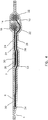
FIG. 2 illustrates a top view of the eyelid stimulator. -
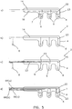
FIG. 3 illustrates a side view of the eyelid stimulator ofFIG. 2 . -
FIG. 4 illustrates a cross-sectional view of the stimulating and neutral electrodes of the eyelid stimulator through section 4-4 ofFIG. 2 . -
FIG. 5 illustrates simplified top view electrode connection schemes. -
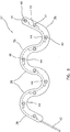
FIG. 6 illustrates a top view of an alternative eyelid stimulator. -
FIG. 7 illustrates the implanted eyelid stimulator connected to an implanted miniature electric generator. -
FIG. 8 illustrates a control scheme for an eyelid stimulator. -
FIG. 9 illustrates a master control scheme for an eyelid stimulator. -
FIG. 10 illustrates a closed loop control scheme for an eyelid stimulator. - The following description is the best mode presently contemplated for carrying out the invention. This description is not to be taken in a limiting sense, but is made merely for the purpose of describing the general principles of the invention. The scope of the invention is determined by the claims.
-
FIG. 1 illustrates relevant facial muscles relating to eyelid stimulation. Aneyelid stimulator 2 and acontroller 3 are illustrated in a preferred implant orientation to a paralyzedeyelid 9. -
Implantable eyelid stimulator 2 is generally illustrated inFIG. 2 . In a preferred embodiment, the overall approximate dimensions of theeyelid stimulator 2, excluding insulatedsignal cable bundle 14 and insulatedneutral cable bundle 16, are less than about 20 mm in length by less than about 10 mm in width, and, as shown inFIG. 3 , less than about 0.50 mm in thickness. Theeyelid stimulator 2 contains an electrode array.Leaflet bodies 4 hold electricallyconductive signal electrodes 6 andneutral electrodes 7 that contact a nerve or a muscle that is to be stimulated. Thesignal electrodes 6 pass a stimulating electrical signal to the nerve or muscle, with theneutral electrodes 7 also contacting the nerve or muscle, thereby completing the stimulation circuit. - It is well known that when a muscle or nerve is electrically stimulated, alternating charge and discharge cycles must be employed to ensure that the muscle continues to respond to the stimulus. Therefore, the terminology of "neutral electrode" and "signal electrode" is arbitrary, because the
neutral electrodes 7 and thesignal electrodes 6 will preferably be reverse biased on each cycle. - Additionally, the
eyelid stimulator 2 may be used as a sensor to detect signals and to transmit these signals to a remotely located signal receiver and processor. Theeyelid stimulator 2 is similar to those disclosed inU.S. Patent Nos. 6,315,721 and6,208,894 . A feature of this preferred embodiment is the flexibility ofleaflet bodies 4, which are free to move with the eyelid and the stimulated muscle. Thesignal electrodes 6 and theneutral electrodes 7 are located in theleaflet body 4.Apertures 30 are located in one surface of theleaflet body 4 to expose thesignal electrodes 6 and theneutral electrodes 7 to the living tissue, thereby allowing electrical contact between the living tissue and thesignal electrodes 6 and theneutral electrode 7. -
Electrode lead body 10,FIG. 2 , is joined to theleaflet bodies 4 such that a joint 12 is formed between theleaflet bodies 4, near the attachment of theleaflet bodies 4 and theelectrode lead body 10. Anchor holes 20 in theelectrode lead body 10 orleaflet bodies 4 preferably provide locations where attachments, such as sutures, may be placed for anchoring theeyelid stimulator 2. Alternately, living tissue may grow into the anchor holes 20, forming an attachment to the living tissue. - The insulated
signal cable bundle 14 and the insulatedneutral cable bundle 16, shown inFIG. 2 , are each connected to a remotely located implanted miniature electric generator 66 (seeFIG. 7 ) that produces electrical impulses that in turn stimulate the nerve or muscle that causes the eyelid to blink. Theelectric generator 66 could be a microstimulator or it could be another type of stimulator. The strands of wire comprising the insulatedsignal cable bundle 14 or insulatedneutral cable bundle 16 are made of a highly conductive metal that is benign in the body, such as MP35N, stainless steel, iridium or an alloy of iridium, platinum or an alloy of platinum, such as platinum-iridium. Preferably, each strand of the wire has a diameter of approximately 0.001 inches. In a preferred embodiment, insulatedsignal cable bundle 14 and insulatedneutral cable bundle 16 are comprised of approximately 19 strands of platinum-20 weight percent iridium wire. The insulatedsignal cable bundle 14 and the insulatedneutral cable bundle 16 are electrically isolated from each other and from the environment in the living tissue byelectrical insulation 32, which is preferably an outer covering of Teflon®, a registered trademark of E.I. du Pont de Nemours and Company, Wilmington, Delaware. - In the preferred embodiment, shown in
FIGS. 2 and 3 , there are approximately sixleaflet bodies 4, each containing onesignal electrode 6 and oneneutral electrode 7. Thesignal electrodes 6 and theneutral electrodes 7 are made of a biocompatible material, such as stainless steel, iridium or an alloy of iridium, platinum or an alloy of platinum, such as platinum-iridium, and in a preferred embodiment, they are platinum-10 weight percent iridium. Typically, thesignal electrodes 6 and theneutral electrodes 7 are essentially identical physically and are approximately 0.50 mm thick and 0.80 mm in diameter. While thesignal electrodes 6 and theneutral electrodes 7 are shown inFIGS. 2 and 3 with the preferred round shape, thesignal electrodes 6 and theneutral electrodes 7 may be of any shape, for example, rectangular, square, oval, or round, etc. - The
eyelid stimulator 2 ofFIGS. 2 and 3 is preferably oriented in the eyelid such that theleaflet bodies 4 lay across the orbicularis oculi muscle 50 (seeFIG. 1 ). Accordingly, as the muscle contracts due to the applied electrical stimulation, theflexible leaflet bodies 4 of the present invention move freely with the muscle. -
FIG. 3 illustrates theeyelid stimulator 2 from a side view and illustrates the insulatedneutral cable bundle 16 entering theelectrode lead body 10 atseal 18. Theelectrode lead body 10 is comprised of atop layer 24 and abottom layer 26 that are joined together. The joint 12 is formed where theleaflet bodies 4 join theelectrode lead body 10. - In the preferred embodiment shown in
FIG. 4 , whereFIG. 4 is the view defined by section 4-4 ofFIG. 2 , signallead wires 23 of the insulatedsignal cable bundle 14 are not insulated from each other. Hence, the insulatedsignal cable bundle 14 and all of thesignal electrodes 6, attached thereto, are stimulated simultaneously. Similarly, all of theneutral lead wires 22 of the insulatedneutral cable bundle 16 are connected together and are connected to theneutral electrodes 7. Allneutral electrodes 7 are therefore at the same neutral voltage.FIG. 5a illustrates a simplified view of the electrodes connection scheme, where thesignal electrodes 6 operate in unison and where theneutral electrodes 7 operate in unison. -
FIG. 5b illustrates a simplified view of the electrodes connection scheme, where an alternative embodiment preferably has a common insulatedsignal cable bundle 14 that is connected to all of thesignal electrodes 6 in theleaflet bodies 4. At least oneground electrode 8, which may be located remote from theeyelid stimulator 2, is in electrical contact with the living tissue. Theground electrode 8 is utilized to complete the circuit. -
FIG. 5c illustrates a simplified view of the electrodes connection scheme, where a further alternative embodiment preferably has theindividual signal electrodes 6 each connected to the individualsignal lead wires 23, such that eachsignal electrode 6 may be individually powered and controlled. Theground electrode 8 may be either locally mounted in theeyelid stimulator 2 or in contact with the living tissue remote from theeyelid stimulator 2. -
FIG. 5d illustrates a simplified view of the electrodes connection scheme, where a further alternative embodiment is described as bipolar pairs, which preferably hasindividual signal electrodes 6 each connected to individualsignal lead wires 23, such that eachsignal electrode 6 may be individually powered. Eachsignal electrode 6 is paired with aneutral electrode 7, forming a bipolar pair. This bipolar pair is powered by an electric pulse generator, such as the implanted miniatureelectric generator 66, where generator 66a powers one bipolar pair, generator 66b powers a second bipolar pair, etc. It is obvious that oneelectric generator 66 may power sequentially or simultaneously one or any combination of bipolar pairs. - While there are numerous schemes for arranging the various electrodes, which may include
signal electrodes 6,neutral electrodes 7, and/or ground electrodes (not illustrated), the preferred manner of arranging theneutral electrodes 7, shown inFIG. 4 , is to attach eachneutral electrode 7 to a separateneutral lead wire 22, that in turn passes along and through theleaflet body 4, along and throughlead body 10, through seal 18 (seeFIGS. 2 and 3 ), and into insulatedneutral cable bundle 16. It is obvious that more than oneneutral electrode 7 can be attached to theneutral lead wire 22. - The
signal electrodes 6 are attached to the separatesignal lead wire 23 that passes through theleaflet bodies 4 and along thelead body 10, through theseal 18, and into the insulatedsignal cable bundle 14. Thelead body 10 is comprised of thetop layer 24 and thebottom layer 26. - The
leaflet bodies 4 and theelectrode lead body 10 are preferably made of a biocompatible material that is electrically insulating. In a preferred embodiment, the biocompatible material is silicone having a hardness of about 70 on the Shore A scale as measured with a durometer. The insulatedsignal cable bundle 14 and insulatedneutral cable bundle 16 pass through theseal 18, which is attached to theelectrode lead body 10. Theseal 18 is preferably made of silicone. In an alternative embodiment, theelectrode lead body 10 and theleaflet bodies 4 are comprised of a biodegradable material that is resorbed by the body post-implantation. It is obvious that the insulatedsignal cable bundle 14 and the insulatedneutral cable bundle 16 may be combined into one cable bundle. - An alternative method (not illustrated) of making the
eyelid stimulator 2 is to utilize a flexible substrate on which a circuit is printed on one surface that is conformal-coated using biocompatible materials. The electrical contact points are made by placing holes through the substrate. Alternatively, contact points may be made by masking the conformal coating or photolithographically patterning the conformal coating. - The
signal electrodes 6 are preferably attached by welding to thesignal lead wire 23 at signal bond joint 34. Similarly, theneutral electrodes 7 are attached by welding to theneutral lead wire 22 at neutral bond joint 36. - The
leaflet bodies 4 are comprised of thetop layer 24 and thebottom layer 26, which are bonded together (seeFIG. 4 ). Sandwiched between thetop layer 24 and thebottom layer 26 is aseparation layer 28. Theseparation layer 28 is preferably comprised of an electrically insulating material that is soft and biocompatible. In a preferred embodiment, theseparation layer 28 is silicone having a hardness of about 70 on the Shore A scale as measured with a durometer. -
FIG. 6 illustrates an alternative embodiment of aneyelid stimulator 37, whereinflexible leg electrodes 40 are contained withinflexible legs 38. Theeyelid stimulator 37 has a generally sinusoidal shape with rounded ends. Theflexible legs 38 are connected byflexible joints 44, which provide flexibility for the apparatus to conform to the eyelid while maintaining electrical contact with the living tissue as it moves during muscle contraction. Theflexible leg electrodes 40 are located withapertures 41 in theflexible legs 38. Theflexible leg electrodes 40 make contact with the nerve or muscle tissue that is to be stimulated by contacting it through theapertures 41 in theflexible legs 38. Preferably, theflexible leg 38 is made of a material, such as silicon, which has a hardness of about 25 on the Shore A scale as measured with a durometer. Theeyelid stimulator 37 is very flexible, allowing it to move and flex with the muscle as it responds to the electrical stimulation. An advantage of this embodiment is that theeyelid stimulator 37 is very soft and flexible, easily conforming to the shape of the eyelid. - The
eyelid stimulator 37 is preferably oriented in the eyelid such that theflexible legs 38 lay across the orbicularis oculi muscle 50 (seeFIG. 1 ). As the orbicularis oculimuscle 50 contracts due to the applied electrical stimulation, theflexible legs 38 move freely with the muscle. - The
flexible leg electrodes 40 may be positive, negative, or neutral biased, depending upon which wire incable bundle 42 is attached to theflexible leg electrodes 40. -
FIG. 7 illustrates an exemplary open loop control system of the present invention wherein an implantedeyelid stimulator 62 is located in an eyelid. The implanted miniatureelectric generator 66 is located in an implanted position under the skin of the patient near the implantedeyelid stimulator 62 and connected to it by atransmission wire 64. In this system, the implanted miniatureelectric generator 66 is controlled by internal programming to generate an electric pulse on a programmed schedule at regular or irregular intervals. In an alternate embodiment, the implanted miniatureelectric generator 66 may receive an electric signal from a remote controller (not illustrated) to generate an electric pulse. Examples of known pulse generators are disclosed byU.S. Patent Nos. 6,185,452 ;6,208,894 ; and6,315,721 . A further alternative embodiment combines the controller with the implantedeyelid stimulator 62. This embodiment is not illustrated. The controller, exemplified byelectric generator 66, is mounted on and therefore is a part ofeyelid stimulator 62. More than onestimulator 62, having a controller integrally mounted thereon, may be connected with othersimilar stimulators 62. Known examples of miniature electric pulse generators are disclosed inU.S. Patent No. 5,999,848 , which describes an implantable sensor/stimulator connectable to a controller. -
FIG. 8 illustrates an exemplary openloop control scheme 100 that coordinates stimulation between a functioningeyelid 111 and a paralyzedeyelid 109 via an implantedeyelid stimulator 112, located in the paralyzedeyelid 109. The implantedeyelid stimulator 112 is controlled by an implanted miniatureelectric pulse generator 104 via atransmission wire 110. Theelectric pulse generator 104,transmission wire 110, andeyelid stimulator 112 in combination form a stimulating device. Known examples of miniature electric pulse generators are disclosed inU.S. Patent Nos. 6,164,284 ;6,185,452 ;6,208,894 ; and6,315,721 - In the open
loop control scheme 100 ofFIG. 8 , a control signal is generated by the functioningeyelid 111, which is detected by an implanted eyelid sensor electrode 114 (similar in structure to that of eyelid stimulator 112) that is located in the muscle of the functioningeyelid 111. The electrical signal is transmitted by asensor wire 106 to acontrol microsensor 102 which, when it receives the signal indicating that the functioningeyelid 111 has closed, sends an electric signal to the implanted miniatureelectric pulse generator 104 via theconnection 108, thereby causing a signal to be generated by the implanted miniatureelectric pulse generator 104 to theeyelid stimulator 112, which causes the paralyzedeyelid 109 to close. Thecontrol microsensor 102,sensor wire 106, andeyelid sensor electrode 114 in combination form a sensing device. Obviously, the implantedeyelid stimulator 112 may be located on the nerves or on the muscles to cause the eyelid to open or to close. The miniatureelectric pulse generator 104 andcontrol microsensor 102 are typical of the miniature monitoring and/or stimulating devices for implantation in living tissue disclosed bySchulman et al. (U.S. Patent No. 6,164,284 ),Schulman et al. (U.S. Patent No. 6,185,452 ), andSchulman et al. (U.S. Patent No. 6,208,894 ) . - Alternatively, the
connection 108 between thecontrol microsensor 102 and the implanted miniatureelectric pulse generator 104 may be sent by wireless means, such as by RF signals, propagated radio signals, or alternating magnetic fields. An embodiment using aconnection 108 that is wireless, simplifies the implantation process by eliminating implantation of a wire. - In a further alternate embodiment (see
FIG. 9 ), the openloop control scheme 100 is illustrated wherein amaster control unit 116 may control one or more implanted miniatureelectric pulse generators 104, to control opening and/or closing of the paralyzedeyelid 109 in a timing sequence determined by themaster control unit 116. This approach is useful to, but not limited to, applications when both eyelids are paralyzed.FIG. 9 illustrates an embodiment where there is one paralyzedeyelid 109 and one functioningeyelid 111. Closing the functioningeyelid 111 causes an electric signal to be generated that triggers the implantedeyelid pulse generators 104 to close the paralyzedeyelid 109. In this embodiment, the signal from the muscle of the functioningeyelid 111 is preferably detected by implantedeyelid sensor electrode 114 and sent to controlmicrosensor 102 bysensor wire 106, which in turn transmits a signal byconnection 107 to themaster control unit 116.Connection 107 may be a wire or an RF signal, propagated radio signal, or alternating magnetic field. Themaster control unit 116 initiates a signal to the implanted miniatureelectric pulse generators 104, which send a signal to the implantedeyelid stimulator 112 bytransmission wire 110, which is implanted in the paralyzedeyelid 109. Thecontrol microsensor 102,sensor wire 106, andeyelid sensor electrode 114 in combination form a sensing device. Theelectric pulse generator 104,transmission wire 110, andeyelid stimulator 112 in combination form a stimulating device. While two implanted miniatureelectric pulse generators 104 are illustrated, each of which is connected to one implantedeyelid stimulator 112, it is obvious that there may be either one or several miniatureelectric pulse generators 104 activated in response to signals from themaster control unit 116. There may also be more than one implantedeyelid stimulator 112 connected to each of the implanted miniatureelectric pulse generators 104. The control signal to the implanted miniatureelectric pulse generators 104, that is generated by themaster control unit 116, travels alongconnections 108, which may be a wire or an RF signal, propagated radio signal, or alternating magnetic field. - A further embodiment (see
FIG. 10 ) is a closedloop control scheme 101 that uses a signal from the paralyzedeyelid 109, which is preferably detected by an implantedeyelid sensor electrode 118 to modify the electric signal that closes the paralyzedeyelid 109. For example, if the paralyzedeyelid 109 fails to close properly, then the electric pulse is increased (in amplitude and/or duration) to properly stimulate theeyelid 109 to close. The electric feedback signal is generated when the paralyzedeyelid 109 closes. Eyelid closure is detected by implantedeyelid sensor electrode 118 and is transmitted to an implanted miniatureelectric pulse sensor 120. A signal is then transmitted to thecontrol microsensor 102 via aconnection 122. Theconnection 122 may be a wire or a wireless signal, such as an RF link. The signal that is sent from thecontrol microsensor 102 to the implanted miniatureelectric pulse generator 104 viaconnection 108 is preferably modified to attain the desired response of the paralyzedeyelid 109 to the electric signal from the implanted miniatureelectric pulse generator 104.U.S. Patent No. 6,164,284 discloses a known closed loop control scheme. Alternately, the feedback may be sent to multiple master controllers rather than to a single controller. Numerous feedback loops from numerous stimulation sites may exist to achieve the desired result. - The eyelid stimulator 2 (
FIG. 1 ) can be used to transmit electrical signals as a therapeutic electrical stimulator. Electrical stimulation of the retina may have a beneficial effect on certain degenerative eye diseases, e.g., age-related macular degeneration (AMD). By virtue of having the eyelid stimulated, the additional benefit of therapeutic electrical stimulation to the eye and/or the retina can be achieved. - Obviously, many modifications and variations of the present invention are possible in light of the above teachings. It is therefore to be understood that, within the scope of the appended claims, the invention may be practiced otherwise than as specifically described.
Claims (17)
- An implantable electrode apparatus suitable for providing or sensing signals from an eyelid, said apparatus comprising:a body of flexible material (10);a plurality of electrically conductive electrodes (6, 7, 40); andat least one lead wire (22, 23) in electrical contact with said conductive electrodes wherein said at least one lead wire is attached to said conductive electrodes;characterized in thatsaid body (10) comprises a plurality of flexible leg portions (4, 38)containing said electrically conductive electrodes (6, 7, 40), at least one of said electrically conductive electrodes (6, 7, 40) being contained in each flexible leg portion.
- The implantable electrode apparatus according to claim 1 wherein said body of flexible material (10) is made of silicone having a hardness of about 70 or less on the Shore A scale as measured with a durometer.
- The implantable electrode apparatus according to claim 1 wherein said flexible leg portions (4, 38)are each made of silicone having a hardness of about 70 or less on the Shore A scale as measured with a durometer.
- The implantable electrode apparatus according to claim 1 wherein said flexible leg portions (4, 38) each have an aperture on one surface which allows said conductive electrode to contact living tissue.
- The implantable electrode apparatus according to claim 1 wherein said at least one electrically conductive electrode (7, 40) is comprised of platinum, a platinum alloy, iridium or an iridium alloy.
- The implantable electrode apparatus according to claim 1 wherein said at least one electrically conductive electrode (7, 40) is capable of being operated as an anode, a cathode, or a ground.
- The implantable electrode apparatus according to claim 1 wherein said at least one lead wire (14, 42) is comprised of MP35N metal alloy, platinum, a platinum metal alloy, or a stainless steel metal alloy.
- The implantable electrode apparatus according to claim 1 wherein said lead wire (14, 42) is attached to said conductive electrode (7, 40) by welding or crimping.
- The implantable electrode apparatus according to claim 1 wherein said body of flexible material (10) includes anchor holes (20).
- The implantable electrode apparatus according to claim 1 additionally comprising a controller (66) mounted on said body of flexible material.
- A system for providing blink stimulation of an eyelid, comprising an implantable electrode apparatus according to any one of claims 1 to 10, and a pulse generator (104) electrically connected to said at least one lead wire.
- The system of claim 11, wherein the system is for periodically producing stimulation pulses to an eyelid;
each leg portion (4, 38) being a leaflet body and the body of flexible material (10) being an electrode lead body suitable for implantation proximal to an eyelid;
the pulse generator (104) being coupled to said at least one electrode in at least one of said leaflet bodies; the system further comprising
means for determining when said at least one electric pulse generator will communicate with said at least one electrode. - The control system according to claim 12 wherein said means for determining when said at least one electric pulse generator (104) will stimulate said at least one electrode is a master control unit (116), wherein said master control unit receives electric signals from a functioning eyelid (111) and transmits electric signals to said at least one electric pulse generator (104).
- The control system according to claim 13 wherein said electric signal between said at least one electric pulse generator (104) and said master control unit (116) is an RF signal.
- The control system according to claim 13 wherein said electric signal between said at least one electric pulse generator (104) and said master control unit (116) is a propagated radio signal.
- The control system according to claim 13 wherein said electric signal between said at least one electric pulse generator (104) and said master control unit (116) is an alternating magnetic field.
- The control system according to claim 12 wherein said apparatus has dimensions less than about 20 mm in length by less than about 10 mm in width and less than about 0.50 mm in thickness.
Applications Claiming Priority (5)
| Application Number | Priority Date | Filing Date | Title |
|---|---|---|---|
| US29937901P | 2001-06-18 | 2001-06-18 | |
| US299379P | 2001-06-18 | ||
| US160804 | 2002-05-31 | ||
| US10/160,804 US6792314B2 (en) | 2001-06-18 | 2002-05-31 | Miniature implantable array and stimulation system suitable for eyelid stimulation |
| PCT/US2002/017852 WO2002102455A1 (en) | 2001-06-18 | 2002-06-05 | Miniature implantable array and stimulation system suitable for eyelid stimulation |
Publications (3)
| Publication Number | Publication Date |
|---|---|
| EP1404405A1 EP1404405A1 (en) | 2004-04-07 |
| EP1404405A4 EP1404405A4 (en) | 2007-01-03 |
| EP1404405B1 true EP1404405B1 (en) | 2012-04-11 |
Family
ID=26857241
Family Applications (1)
| Application Number | Title | Priority Date | Filing Date |
|---|---|---|---|
| EP02739717A Expired - Lifetime EP1404405B1 (en) | 2001-06-18 | 2002-06-05 | Miniature implantable array and stimulation system suitable for eyelid stimulation |
Country Status (3)
| Country | Link |
|---|---|
| US (1) | US6792314B2 (en) |
| EP (1) | EP1404405B1 (en) |
| WO (1) | WO2002102455A1 (en) |
Families Citing this family (85)
| Publication number | Priority date | Publication date | Assignee | Title |
|---|---|---|---|---|
| US20050021118A1 (en) * | 2000-07-13 | 2005-01-27 | Chris Genau | Apparatuses and systems for applying electrical stimulation to a patient |
| JP4204066B2 (en) * | 2002-12-05 | 2009-01-07 | 保雄 田野 | Artificial vision system |
| US7321795B2 (en) * | 2003-03-24 | 2008-01-22 | Les Bogdanowicz | Compositions for electric stimulation of the eye |
| US7035692B1 (en) * | 2003-04-30 | 2006-04-25 | The Regents Of The University Of California | High density polymer-based integrated electrode array |
| US9278208B1 (en) | 2003-10-20 | 2016-03-08 | University Of Central Florida Research Foundation, Inc. | Spatial-temporal deep brain stimulation methods and systems |
| US8024049B1 (en) | 2003-10-20 | 2011-09-20 | University Of Central Florida Research Foundation, Inc. | Spatial-temporal deep brain stimulation methods and systems |
| GB0409769D0 (en) * | 2004-04-30 | 2004-06-09 | Algotec Ltd | Electrical nerve stimulation device |
| US9168383B2 (en) | 2005-10-14 | 2015-10-27 | Pacesetter, Inc. | Leadless cardiac pacemaker with conducted communication |
| EP2471450A1 (en) | 2005-10-14 | 2012-07-04 | Nanostim, Inc. | Leadless cardiac pacemaker and system |
| CN100591391C (en) * | 2006-07-28 | 2010-02-24 | 中国科学院上海微系统与信息技术研究所 | Implantable microelectrode with integrated drug release function, manufacturing method and application |
| DE102006048819A1 (en) * | 2006-10-10 | 2008-04-17 | NMI Naturwissenschaftliches und Medizinisches Institut an der Universität Tübingen | Device with a basic body |
| US20080103572A1 (en) | 2006-10-31 | 2008-05-01 | Medtronic, Inc. | Implantable medical lead with threaded fixation |
| US8019443B2 (en) | 2008-04-01 | 2011-09-13 | Boston Scientific Neuromodulation Corporation | Anchoring units for leads of implantable electric stimulation systems and methods of making and using |
| US9320891B2 (en) * | 2008-04-02 | 2016-04-26 | Boston Scientific Neuromodulation Corporation | Lead anchor for implantable devices and methods of manufacture and use |
| US8685093B2 (en) | 2009-01-23 | 2014-04-01 | Warsaw Orthopedic, Inc. | Methods and systems for diagnosing, treating, or tracking spinal disorders |
| US8126736B2 (en) | 2009-01-23 | 2012-02-28 | Warsaw Orthopedic, Inc. | Methods and systems for diagnosing, treating, or tracking spinal disorders |
| US8527068B2 (en) | 2009-02-02 | 2013-09-03 | Nanostim, Inc. | Leadless cardiac pacemaker with secondary fixation capability |
| US8442641B2 (en) | 2010-08-06 | 2013-05-14 | Nano-Retina, Inc. | Retinal prosthesis techniques |
| US8428740B2 (en) | 2010-08-06 | 2013-04-23 | Nano-Retina, Inc. | Retinal prosthesis techniques |
| US8150526B2 (en) * | 2009-02-09 | 2012-04-03 | Nano-Retina, Inc. | Retinal prosthesis |
| US8706243B2 (en) | 2009-02-09 | 2014-04-22 | Rainbow Medical Ltd. | Retinal prosthesis techniques |
| US8718784B2 (en) | 2010-01-14 | 2014-05-06 | Nano-Retina, Inc. | Penetrating electrodes for retinal stimulation |
| US9887470B2 (en) | 2009-04-27 | 2018-02-06 | Boston Scienific Neuromodulation Corporation | Torque lock anchor and methods and devices using the anchor |
| US9352147B2 (en) | 2009-04-27 | 2016-05-31 | Boston Scientific Neuromodulation Corporation | Torque lock anchor and methods and devices using the anchor |
| US9061134B2 (en) * | 2009-09-23 | 2015-06-23 | Ripple Llc | Systems and methods for flexible electrodes |
| US9060692B2 (en) | 2010-10-12 | 2015-06-23 | Pacesetter, Inc. | Temperature sensor for a leadless cardiac pacemaker |
| WO2012051237A1 (en) | 2010-10-12 | 2012-04-19 | Nanostim, Inc. | Temperature sensor for a leadless cardiac pacemaker |
| CN103249454A (en) | 2010-10-13 | 2013-08-14 | 内诺斯蒂姆股份有限公司 | Leadless pacemaker with anti-swivel construction |
| CA2817589A1 (en) | 2010-11-16 | 2012-05-24 | The Board Of Trustees Of The Leland Stanford Junior University | Systems and methods for treatment of dry eye |
| US9821159B2 (en) | 2010-11-16 | 2017-11-21 | The Board Of Trustees Of The Leland Stanford Junior University | Stimulation devices and methods |
| EP2651502B1 (en) | 2010-12-13 | 2016-11-09 | Pacesetter, Inc. | Pacemaker retrieval systems |
| EP2651494B1 (en) | 2010-12-13 | 2017-02-15 | Pacesetter, Inc. | Delivery catheter |
| WO2012088118A1 (en) | 2010-12-20 | 2012-06-28 | Nanostim, Inc. | Leadless pacemaker with radial fixation mechanism |
| US8571669B2 (en) | 2011-02-24 | 2013-10-29 | Nano-Retina, Inc. | Retinal prosthesis with efficient processing circuits |
| US9511236B2 (en) | 2011-11-04 | 2016-12-06 | Pacesetter, Inc. | Leadless cardiac pacemaker with integral battery and redundant welds |
| US8781594B2 (en) | 2011-12-14 | 2014-07-15 | Med-El Elektromedizinische Geraete Gmbh | System and method for eyelid simulation |
| AU2013237171B2 (en) * | 2012-03-23 | 2017-04-20 | Microarray Limited | Skin dressing with electrodes and physiologically active precursor substance |
| JP2015513980A (en) * | 2012-04-05 | 2015-05-18 | ザ リージェンツ オブ ザ ユニバーシティ オブ カリフォルニア | Subcutaneous electrode for cranial nerve stimulation |
| EP2879758B1 (en) | 2012-08-01 | 2018-04-18 | Pacesetter, Inc. | Biostimulator circuit with flying cell |
| US8849408B1 (en) | 2013-01-04 | 2014-09-30 | University Of Central Florida Research Foundation, Inc. | Methods for electronic directionality of deep-brain stimulation |
| WO2014110575A1 (en) | 2013-01-14 | 2014-07-17 | Massachusetts Eye & Ear Infirmary | Facial movement and expression detection and stimulation |
| WO2014138709A1 (en) | 2013-03-08 | 2014-09-12 | Oculeve, Inc. | Devices and methods for treating dry eye in animals |
| US9717627B2 (en) | 2013-03-12 | 2017-08-01 | Oculeve, Inc. | Implant delivery devices, systems, and methods |
| US9370417B2 (en) | 2013-03-14 | 2016-06-21 | Nano-Retina, Inc. | Foveated retinal prosthesis |
| EP2986339A4 (en) | 2013-04-19 | 2016-12-21 | Oculeve Inc | DEVICES AND METHODS FOR NASAL STIMULATION |
| US9216563B2 (en) | 2013-08-19 | 2015-12-22 | Boston Scientific Neuromodulation Corporation | Lead anchor with adhesive and systems and methods using the lead anchor |
| US9517334B2 (en) | 2013-08-19 | 2016-12-13 | Boston Scientific Neuromodulation Corporation | Lead anchors and systems and methods employing the lead anchors |
| US9474902B2 (en) | 2013-12-31 | 2016-10-25 | Nano Retina Ltd. | Wearable apparatus for delivery of power to a retinal prosthesis |
| US9331791B2 (en) | 2014-01-21 | 2016-05-03 | Nano Retina Ltd. | Transfer of power and data |
| JP6604963B2 (en) | 2014-02-25 | 2019-11-20 | オキュリーブ, インコーポレイテッド | Polymer formulations for nasolacrimal gland stimulation |
| US9415212B2 (en) | 2014-02-28 | 2016-08-16 | Boston Scientific Neuromodulation Corporation | Side loading lead anchor and methods of making and using thereof |
| US9987482B2 (en) | 2014-05-27 | 2018-06-05 | Boston Scientific Neuromodulation Corporation | Systems and methods for making and using reversible mechanical lead anchors for electrical stimulation systems |
| CA2956176A1 (en) | 2014-07-25 | 2016-01-28 | Oculeve, Inc. | Stimulation patterns for treating dry eye |
| US9802038B2 (en) * | 2014-08-15 | 2017-10-31 | Axonics Modulation Technologies, Inc. | Implantable lead affixation structure for nerve stimulation to alleviate bladder dysfunction and other indication |
| JP6735742B2 (en) | 2014-10-22 | 2020-08-05 | オキュリーブ, インコーポレイテッド | Stimulator and method for the treatment of dry eye |
| US10207108B2 (en) | 2014-10-22 | 2019-02-19 | Oculeve, Inc. | Implantable nasal stimulator systems and methods |
| AU2015335772B2 (en) | 2014-10-22 | 2020-07-09 | Oculeve, Inc. | Contact lens for increasing tear production |
| US9636498B2 (en) | 2015-08-03 | 2017-05-02 | Boston Scientific Neuromodulation Corporation | Lead anchor with a wedge and systems using the lead anchor |
| WO2017048731A1 (en) | 2015-09-15 | 2017-03-23 | Amerivision International, Inc. | Apparatus and method for ocular microcurrent stimulation therapy |
| US10426958B2 (en) | 2015-12-04 | 2019-10-01 | Oculeve, Inc. | Intranasal stimulation for enhanced release of ocular mucins and other tear proteins |
| US10252048B2 (en) | 2016-02-19 | 2019-04-09 | Oculeve, Inc. | Nasal stimulation for rhinitis, nasal congestion, and ocular allergies |
| US10071242B2 (en) | 2016-02-29 | 2018-09-11 | Boston Scientific Neuromodulation Corporation | Lead anchor for an electrical stimulation system |
| US10918864B2 (en) | 2016-05-02 | 2021-02-16 | Oculeve, Inc. | Intranasal stimulation for treatment of meibomian gland disease and blepharitis |
| US10369354B2 (en) | 2016-05-17 | 2019-08-06 | Boston Scientific Neuromodulation Corporation | Systems and method for anchoring a lead for neurostimulation of a target anatomy |
| RU2019118600A (en) | 2016-12-02 | 2021-01-11 | Окулив, Инк. | APPARATUS AND METHOD FOR MAKING DRY EYE SYNDROME PREDICTION AND TREATMENT RECOMMENDATIONS |
| US10709886B2 (en) | 2017-02-28 | 2020-07-14 | Boston Scientific Neuromodulation Corporation | Electrical stimulation leads and systems with elongate anchoring elements and methods of making and using |
| US10835739B2 (en) | 2017-03-24 | 2020-11-17 | Boston Scientific Neuromodulation Corporation | Electrical stimulation leads and systems with elongate anchoring elements and methods of making and using |
| US10857351B2 (en) | 2017-04-28 | 2020-12-08 | Boston Scientific Neuromodulation Corporation | Lead anchors for electrical stimulation leads and systems and methods of making and using |
| WO2018227019A1 (en) | 2017-06-07 | 2018-12-13 | Neuronexus Technologies, Inc. | Systems and methods for flexible electrode arrays |
| US10959674B2 (en) | 2017-10-23 | 2021-03-30 | Datafeel Inc. | Communication devices, methods, and systems |
| US10729564B2 (en) | 2018-01-12 | 2020-08-04 | Ripple Llc | Sensor system |
| EP3755418B1 (en) | 2018-02-22 | 2023-06-21 | Axonics, Inc. | Neurostimulation leads for trial nerve stimulation |
| EP3801746B1 (en) | 2018-08-14 | 2023-05-10 | Neurotrigger Ltd. | Apparatus for transcutaneous facial nerve stimulation |
| US11338139B2 (en) | 2018-10-01 | 2022-05-24 | Biovisics Medical, Inc. | System and methods for controlled electrical modulation for vision therapy |
| US11305118B2 (en) | 2018-11-30 | 2022-04-19 | Biovisics Medical, Inc. | Head worn apparatuses for vision therapy |
| US20220047866A1 (en) | 2018-12-20 | 2022-02-17 | I-Lumen Scientific, Inc. | Apparatus and method for microcurrent stimulation therapy |
| CN109718468A (en) * | 2019-01-13 | 2019-05-07 | 常州瑞神安医疗器械有限公司 | A kind of external current electrode |
| EP3952979A1 (en) | 2019-04-10 | 2022-02-16 | Biovisics Medical, Inc. | Systems and interfaces for ocular therapy |
| US11511112B2 (en) | 2019-06-14 | 2022-11-29 | Biovisics Medical, Inc. | Wearable medical device |
| WO2021011255A1 (en) | 2019-07-12 | 2021-01-21 | Biovisics Medical, Inc. | Ocular therapy modes and systems |
| WO2021069058A1 (en) * | 2019-10-07 | 2021-04-15 | Abuyousef Nuha Awni | System, device and method to induce eyelid movement |
| US12420103B1 (en) | 2020-08-20 | 2025-09-23 | Axonics, Inc. | Neurostimulation leads with reduced current leakage |
| KR20240083855A (en) | 2020-10-30 | 2024-06-12 | 데이터필 인코포레이티드 | Wearable data communication devices, kits, methods, and systems |
| USD1010832S1 (en) * | 2021-12-01 | 2024-01-09 | I-Lumen Scientific, Inc. | Medical electrode |
| US12589243B2 (en) | 2022-10-21 | 2026-03-31 | I-Lumen Scientific, Inc. | Ocular devices and controller interfaces for ocular therapy |
Family Cites Families (14)
| Publication number | Priority date | Publication date | Assignee | Title |
|---|---|---|---|---|
| US4271841A (en) | 1980-01-31 | 1981-06-09 | Medtronic, Inc. | Electro-ocular stimulation system |
| US4799487A (en) | 1987-05-11 | 1989-01-24 | Bleicher Joel N | Reanimation device and method for treating the paralyzed face |
| US5324322A (en) | 1992-04-20 | 1994-06-28 | Case Western Reserve University | Thin film implantable electrode and method of manufacture |
| US5255692A (en) | 1992-09-04 | 1993-10-26 | Siemens Aktiengesellschaft | Subcostal patch electrode |
| DE4433111A1 (en) * | 1994-09-16 | 1996-03-21 | Fraunhofer Ges Forschung | Cuff electrode |
| US5843147A (en) | 1996-04-30 | 1998-12-01 | Medtronic, Inc. | Implantable eyelid electrode and method of implanting same |
| CA2281880C (en) | 1997-02-26 | 2007-03-06 | Alfred E. Mann Foundation For Scientific Research | Battery-powered patient implantable device |
| US6208894B1 (en) | 1997-02-26 | 2001-03-27 | Alfred E. Mann Foundation For Scientific Research And Advanced Bionics | System of implantable devices for monitoring and/or affecting body parameters |
| US6164284A (en) | 1997-02-26 | 2000-12-26 | Schulman; Joseph H. | System of implantable devices for monitoring and/or affecting body parameters |
| US5917346A (en) | 1997-09-12 | 1999-06-29 | Alfred E. Mann Foundation | Low power current to frequency converter circuit for use in implantable sensors |
| US6259937B1 (en) | 1997-09-12 | 2001-07-10 | Alfred E. Mann Foundation | Implantable substrate sensor |
| US5999849A (en) | 1997-09-12 | 1999-12-07 | Alfred E. Mann Foundation | Low power rectifier circuit for implantable medical device |
| US5999848A (en) | 1997-09-12 | 1999-12-07 | Alfred E. Mann Foundation | Daisy chainable sensors and stimulators for implantation in living tissue |
| US6088608A (en) | 1997-10-20 | 2000-07-11 | Alfred E. Mann Foundation | Electrochemical sensor and integrity tests therefor |
-
2002
- 2002-05-31 US US10/160,804 patent/US6792314B2/en not_active Expired - Lifetime
- 2002-06-05 EP EP02739717A patent/EP1404405B1/en not_active Expired - Lifetime
- 2002-06-05 WO PCT/US2002/017852 patent/WO2002102455A1/en not_active Ceased
Also Published As
| Publication number | Publication date |
|---|---|
| EP1404405A4 (en) | 2007-01-03 |
| US20030023297A1 (en) | 2003-01-30 |
| WO2002102455A8 (en) | 2004-05-21 |
| WO2002102455A1 (en) | 2002-12-27 |
| US6792314B2 (en) | 2004-09-14 |
| EP1404405A1 (en) | 2004-04-07 |
Similar Documents
| Publication | Publication Date | Title |
|---|---|---|
| US6792314B2 (en) | Miniature implantable array and stimulation system suitable for eyelid stimulation | |
| US7628750B2 (en) | Actuation and control of limbs through motor nerve stimulation | |
| Szeto et al. | Sensory feedback using electrical stimulation of the tactile sense | |
| Navarro et al. | A critical review of interfaces with the peripheral nervous system for the control of neuroprostheses and hybrid bionic systems | |
| EP1706178B1 (en) | System for routing electrical current to bodily tissues via implanted passive conductors | |
| CN103313754B (en) | Systems and methods for treating dry eye | |
| JP5188494B2 (en) | System and method using multiple timing channels for electrode adjustment during implant stimulator setup | |
| US20070049988A1 (en) | Optimal electrode contact polarity configurations for implantable stimulation systems | |
| Loeb | Neural prosthetic interfaces with the nervous system | |
| Mokwa et al. | Intraocular epiretinal prosthesis to restore vision in blind humans | |
| US20240325757A1 (en) | Devices and methods for improving headache disorders | |
| Peckham et al. | Implantable neural stimulators | |
| CN110270009B (en) | Extraocular electrode array device for local electrical stimulation of retina | |
| Uhlir et al. | Performance of epimysial stimulating electrodes in the lower extremities of individuals with spinal cord injury | |
| Kelly et al. | Realization of a 15-channel, hermetically-encased wireless subretinal prosthesis for the blind | |
| Prodanov et al. | Functional electric stimulation for sensory and motor functions: progress and problems | |
| Popovic et al. | Recruitment and comfort of BION implanted electrical stimulation: implications for FES applications | |
| US12138466B2 (en) | Cable-less lead adapter for implantable neurostimulator system | |
| Stieglitz | Neural prostheses in clinical practice: biomedical microsystems in neurological rehabilitation | |
| JP2024528224A (en) | Systems and methods for inducing muscle contraction | |
| Sherwood et al. | Biomedical engineering specifications for epidural spinal cord stimulation to augment motor performance | |
| Meadows | Portable electrical stimulation systems | |
| Bijak et al. | Functional and biological test of a 20 channel implantable stimulator in sheep in view of functional electrical stimulation walking for spinal cord injured persons | |
| Popovic | Neural prostheses for movement restoration | |
| Normann et al. | Control of skeletal muscle force with currents injected via an intrafascicular, microelectrode array |
Legal Events
| Date | Code | Title | Description |
|---|---|---|---|
| PUAI | Public reference made under article 153(3) epc to a published international application that has entered the european phase |
Free format text: ORIGINAL CODE: 0009012 |
|
| 17P | Request for examination filed |
Effective date: 20040107 |
|
| AK | Designated contracting states |
Kind code of ref document: A1 Designated state(s): AT BE CH CY DE DK ES FI FR GB GR IE IT LI LU MC NL PT SE TR |
|
| AX | Request for extension of the european patent |
Extension state: AL LT LV MK RO SI |
|
| RIC1 | Information provided on ipc code assigned before grant |
Ipc: 7A 61N 1/04 A |
|
| A4 | Supplementary search report drawn up and despatched |
Effective date: 20061201 |
|
| RIC1 | Information provided on ipc code assigned before grant |
Ipc: A61N 1/05 20060101AFI20061127BHEP |
|
| 17Q | First examination report despatched |
Effective date: 20080813 |
|
| GRAP | Despatch of communication of intention to grant a patent |
Free format text: ORIGINAL CODE: EPIDOSNIGR1 |
|
| RAP1 | Party data changed (applicant data changed or rights of an application transferred) |
Owner name: ALFRED E. MANN FOUNDATION FOR SCIENTIFIC RESEARCH |
|
| GRAS | Grant fee paid |
Free format text: ORIGINAL CODE: EPIDOSNIGR3 |
|
| GRAA | (expected) grant |
Free format text: ORIGINAL CODE: 0009210 |
|
| AK | Designated contracting states |
Kind code of ref document: B1 Designated state(s): DE GB |
|
| REG | Reference to a national code |
Ref country code: GB Ref legal event code: FG4D |
|
| REG | Reference to a national code |
Ref country code: DE Ref legal event code: R096 Ref document number: 60242632 Country of ref document: DE Effective date: 20120531 |
|
| PLBE | No opposition filed within time limit |
Free format text: ORIGINAL CODE: 0009261 |
|
| STAA | Information on the status of an ep patent application or granted ep patent |
Free format text: STATUS: NO OPPOSITION FILED WITHIN TIME LIMIT |
|
| 26N | No opposition filed |
Effective date: 20130114 |
|
| REG | Reference to a national code |
Ref country code: DE Ref legal event code: R097 Ref document number: 60242632 Country of ref document: DE Effective date: 20130114 |
|
| PGFP | Annual fee paid to national office [announced via postgrant information from national office to epo] |
Ref country code: GB Payment date: 20170627 Year of fee payment: 16 |
|
| PGFP | Annual fee paid to national office [announced via postgrant information from national office to epo] |
Ref country code: DE Payment date: 20170628 Year of fee payment: 16 |
|
| REG | Reference to a national code |
Ref country code: DE Ref legal event code: R119 Ref document number: 60242632 Country of ref document: DE |
|
| GBPC | Gb: european patent ceased through non-payment of renewal fee |
Effective date: 20180605 |
|
| PG25 | Lapsed in a contracting state [announced via postgrant information from national office to epo] |
Ref country code: GB Free format text: LAPSE BECAUSE OF NON-PAYMENT OF DUE FEES Effective date: 20180605 Ref country code: DE Free format text: LAPSE BECAUSE OF NON-PAYMENT OF DUE FEES Effective date: 20190101 |