EP1404168A2 - Kaskadiertes Spülgassystem - Google Patents
Kaskadiertes Spülgassystem Download PDFInfo
- Publication number
- EP1404168A2 EP1404168A2 EP03255755A EP03255755A EP1404168A2 EP 1404168 A2 EP1404168 A2 EP 1404168A2 EP 03255755 A EP03255755 A EP 03255755A EP 03255755 A EP03255755 A EP 03255755A EP 1404168 A2 EP1404168 A2 EP 1404168A2
- Authority
- EP
- European Patent Office
- Prior art keywords
- pressure
- fluid
- pressurized fluid
- data component
- data
- Prior art date
- Legal status (The legal status is an assumption and is not a legal conclusion. Google has not performed a legal analysis and makes no representation as to the accuracy of the status listed.)
- Withdrawn
Links
Images



Classifications
-
- H—ELECTRICITY
- H05—ELECTRIC TECHNIQUES NOT OTHERWISE PROVIDED FOR
- H05K—PRINTED CIRCUITS; CASINGS OR CONSTRUCTIONAL DETAILS OF ELECTRIC APPARATUS; MANUFACTURE OF ASSEMBLAGES OF ELECTRICAL COMPONENTS
- H05K5/00—Casings, cabinets or drawers for electric apparatus
- H05K5/06—Hermetically-sealed casings
Definitions
- the present invention relates to systems used for protecting electronic, mechanical, hydraulic or other components from the effects of harsh environments that may exist in industrial facilities.
- U.S. Patent No. 5,603,892 provides a gas purged electronics enclosure in which a control system is used to open and close valves to purge a contaminant-free gas through the electronics enclosure.
- a getter material is used as a scavenger to ensure the removal of contaminants.
- This patent describes a system that has only one enclosure for housing electronic components.
- the present invention provides a system that protects electronic and other components from the outside environment by means of continuously cascading a flowing pressurized gas through the system to prevent harsh environmental conditions from adversely effecting system components' and the components ability to monitor a plurality of plant operations.
- the present invention is an integral cascaded distributed purge system used to protect interconnected electronic components, although the system is not limited to such electronic components.
- the system is particularly useful in industrial applications where the surrounding environment can adversely affect electronic components. For example, in a food plant, cleaning procedures require that hot water, strong caustic detergents and steam be used to wash down equipment. This creates an atmosphere where moisture can inadvertently enter into a sealed enclosure, ultimately leading to electronic failures.
- the distributed purge gas system of the present invention electronic devices located at different points in a process are protected by an integrated system that continuously purges pressurized gas through the system. This is accomplished in an efficient and cost effective manner, i.e. through already existing interconnecting cabling and fixtures.
- the system is capable of providing protection to the entire system of separately housed electronic devices from a single highly reliable source.
- the present invention is a system for protecting electronic or other components from contamination, which includes a tightly controlled, multi-tiered distribution means; a pressurized gas in fluid communication with the distribution means; a plurality of apparatus for enclosing electronic devices connected to the distribution means, with each apparatus connected to the distribution means by a conduit having a first end and a second end, wherein the first end is connected to the distribution means and the second end is connected to the apparatus.
- the present invention also includes:
- the present invention prevents moisture and contaminants from the surrounding process environment from contacting for example, electronic or mechanical components, or data gathering devices situated in the environment.
- contaminants as used herein means moisture, particulate matter or any other substance which may adversely impact the components and their operation.
- FIG. 1 electronic components are protected in a distributed or cascaded purge gas system of the present invention shown generally at 10, where pressurized gas is directed to flow from 12 into a distribution means such as distribution manifold 20.
- the manifold 20 distributes the pressurized gas through a conduit, such as cable or conduit 40, to apparatuses 22, 23, 24, 25 and 26 ("22-26"), which house the electronic or mechanical components at different locations along the process.
- the components are constructed to generate signals representing data sensed at locations in a plant or processing environment.
- the manifold includes electric components (not shown) for the system. These components are constructed and arranged as transceivers, i.e. to receive sensor signals from the apparatus 22-26 via the conduit 40 and in turn generate a data signal to another remote location reporting on the production environment being sensed and monitored.
- each of the apparatus 22-26 can be used for different sensory functions, i.e., the sensing of temperature, pressure, humidity, flow, level, noise, etc. of other devices or systems being monitored or controlled by the system 10.
- Each manifold 20 in combination with the apparatus 22-26 are referred to herein as a hub network 14.
- a hub network 14 preferably includes one manifold 20, at least one of the apparatus 22-26 and the conduit 40 connecting the manifold and apparatus selected. However, for most processing environments, a plurality of apparatus will be connected to the manifold 20. See for example, Figure 2.
- the system 10 may include a plurality of the hub networks 14 for a single plant facility. Where a plurality of hub networks 14 are used, the manifolds 20 will be preferably arranged in parallel.
- Each apparatus 22-26 is designed with a pressure or flow control means such as check valve 30.
- the valve 30 allows the manifold 20 and therefore the system 10 to purge pressurized gas through each apparatus serially or in parallel by continuously (if necessary) venting or bleeding a portion of the pressurized gas through the check valve to maintain the system 10 at a desired pressure.
- the valve 30 is set to open and release the pressurized gas at a predetermined pressure.
- the check valve 30 continuously controls the pressurized gas at a preferred pressure to be about 1 to 2 psi above the next level in the flow cascade and at the least, to maintain a pressure within the system 10 above that of the plant environment so that moisture, for example, is prevented from entering the apparatus 22-26 in the system 10.
- a pressurized wall of a fluid preferably a gas
- a fluid preferably a gas
- the check valve 30 will typically hold the internal pressure of the final apparatus at about 0.5 to 1 psi above the surrounding external environment.
- Figure 2 represents another embodiment of a distributed purge system of the present invention shown generally at 100.
- Pressurized gas is supplied from supply tank 50 and directed to filter 58 for removal of contaminants and moisture.
- the pressure of the pressurized gas is decreased through a series of pressure regulating valves 52 and 54.
- pressurized gas from the supply tank 50 may be at about 45 psi.
- the pressure is reduced to 35 psi by pressure regulating valve 52 and then reduced further to 30 psi by pressure regulating valve 54.
- the supply tank 50 may contain liquid nitrogen (LN) for use with the system 100.
- a supply tank 51 contains compressed dry air, which air can be sourced from the immediate facility in which the system 100 is operating.
- a solid state membrane air dryer can be used which provides (-)40° F dewpoint air; which is a very dry air.
- the compressed dry air can be introduced from the tank 51 to the system 100 through either line 51a or 51b.
- the selection of line 51a or 51b will be determined by whether or not the compressed dry air is to be introduced upstream or downstream of the pressure regulating valve 52. Regardless of which of the lines 51a, 51b is used, it is preferred to introduce the compressed dry air from the tank 51 upstream of the filter 58 to take advantage of filtering the air to be introduced into the system 100.
- Differential flow control module 56 modulates the pressure of its effluent pressurized gas to control the flow of the pressurized gas into the distribution manifold 20.
- pressurized gas at about 30 psi may be continuously modulated at about 2 psi at the effluent of the flow control module 56.
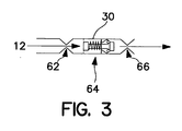
- the pressurized gas 12 is shown flowing continuously through conduit 40 into the apparatuses 22-26, such as for example, apparatus 22, and being exhausted through check valve 30, which is shown in greater detail in Figure 3.
- the apparatuses 22-26 are shown with sensing means 34, which is a part of the respective one of the apparatus 22-26.
- the sensing means 34 can optionally be constructed and arranged within each apparatus.
- the sensing means is in communication with a process, system or apparatus (not shown) of the host facility by connector 35. Where a plurality of the hub networks 14 are used, the sensing means 34 are preferably arranged in series.
- the control module 56 is provided for each manifold 20 and preferably for each hub network 14.
- the module 56 preferably includes a needle valve and a constant differential relay.
- the carefully controlled pressurized gas-sharing arrangement minimizes the number of separate pressurized gas supply sources that are needed by doing away with the closed system arrangement used in the prior art, where each electronic device is housed in its own system, thereby greatly increasing complexity and material costs.
- the system 10,100 of the present invention easily and capably maintains pressure in the system by controlling, via cascade, the flow of the pressurized gas through a multitude of apparatuses 22-26 that house electronic devices in the system by utilizing "cracking" or relief pressures of the check valves 30 installed in each apparatus to apportion the flow.
- apparatuses 22-26 are shown in Figure1, it should be understood that the present invention will provide protection for one or a plurality of cascaded levels of purged enclosures. This protection is achieved from the present system also utilizing the existing cascaded electrical connectivity of the distributed electronics system to distribute the purge gas.
- the distribution means may be any suitable device that is capable of distributing pressurized gas 12 to each apparatus 22-26, which house an electronic device.
- the apparatus 22-26 may each alternatively be connected to or in communication with an electronic device, rather than actually house the electronic device. In such an arrangement, the cascade effect of maintaining pressure is still employed to protect the system 10, 100.
- the distribution manifold 20 is hermetically sealed to reduce the possibility of contaminants from entering the system 10,100 and to maintain a positive pressure within the system. It should be noted that the hermetic seal by itself may not be sufficient in preventing moisture, i.e. steam or condensate, or other contaminants from entering or forming in the distribution manifold 20. By continuously purging the system with pressurized gas, the gas in the system is constantly changing, thus decreasing the chance of moisture or contaminant collection and formation.
- a pressure control device such as check valve 32 shown in Figure 2, may be connected to the distribution manifold 20 to assist in adjusting the pressure of gas in the manifold 20.
- Non-limiting examples of the distribution manifold 20 include boxes, enclosures, electrical panels, manifolds, pipes, tubes, electrical cables and conduits, and intermediate storage canisters or tanks.
- pressurized gas 12 can be any inert gas source.
- inert gases is intended to mean any gas that will not react with, and in the environment created within, the apparatus or system.
- nitrogen, helium, compressed dry air or instrumentation air of relatively high purity with minimal moisture content are some of the many inert gases that may be used with the system 10,100 of the present invention.
- the pressurized gas is superdried compressed air having a dewpoint of about -40°F.
- a flow control check valve 30 shown in Figure 3 is an example of a device that is capable of providing flow control by modulating pressure from upstream in the system.
- Pressurized gas 12 flows into the flow control valve 30 from the electronics or other enclosure, first passing through fixed restriction zone 62, then into the variable restriction zone 64.
- the variable restriction zone 64 is shown as a spring mechanism, which opens the check valve when the pressure exceeds a predetermined value.
- the pressurized gas then passes through a second fixed restriction zone 66 for exiting the flow control valve 30.
- a device that can control the flow of a pressurized gas may be used.
- Particularly preferred is a ball and spring type valve device, or diaphragm actuated check valve.
- the flow control check valve 30 may be located at an exterior surface of each of the apparatus 22-26 for allowing gas to continuously exit the respective apparatus 22-26 and hence, the system 10, 100.
- the system 10,100 of the present invention may have a plurality of manifolds 20 for housing electronic components from the outside environment.
- the manifold for enclosing the electronic components preferably includes: an enclosure preferably formed of a continuous sidewall having an opening at one end thereof to provide access to an interior of manifold 20 in the interior of the enclosure.
- Electronic components are disposed at an interior of the enclosure, which interior is in a fluid communication with the conduit 40 and also provided with the check valve 32.
- the access opening for the enclosure is provided with a substantially tamper proof cover for the opening to prevent access to the internal components and contamination thereof. Complete replacement or turnover of all gas within the entire system occurs three to ten times per hour for optimum protection of the system
- the apparatus shown in Figure 4 shows an example of an apparatus 22 for enclosing or communicating with the electronic or mechanical devices in the plant.
- Pressurized gas 72 is distributed to apparatus 22 via cable 40, which is connected to apparatus 22 by receptacle 36.
- Pressurized gas 72 circulates within a housing 70 of the apparatus 22.
- pressurized gas 74 exits housing 70 through flow control check valve 30 and exhausts to the atmosphere 76.
- the apparatus 22-26 may include its own integral sensor 75 or such sensor 75 may be disposed at a remote location and connected to the apparatus 22 by another cable or conduit similar to that of conduit 40.
- a flow control check valve 30 may also be used with the sensor 75 disposed at the remote location.
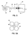
- each conduit 40 has a first end such as receptacle 33 that is connected to the manifold 20 and a second end such as receptacle 36 that connects to the respective one of the apparatus 22-26 at a mating receptacle 37.
- the receptacles 33, 36, 37 are preferably impervious to water and do not allow the gas to escape the system.
- a passageway 38 extends through the conduit 40 preferably between contact pins 39 of the receptacle 33.
- a tube 41 extends through the passageway 38 or core of the conduit.
- the tube 41 provides passage for the pressurized gas between and among the elements of the system.
- modified part P/N FS 4.4-0.5/14.5 microstyle DC receptacles available from Turck, Inc. are used.
- the receptacles are multi-pin male connectors, which are mated to molded female connectors having shielded or jacketed cables for connection of the electronic circuitry internal to the enclosure to a central computer or other external electronics.
- flow and pressure profiles for the present system 10, 100 can be realized by the construction, control and disposition of the system in the corresponding facility or plant.
- pressure control points are preferably realized at regulating valves 52 and 54, as well as check valve 32 and variable restriction zone 64.
- Flow control points for the present system 10, 100 are realized at flow control module 56 and fixed restriction zones 62, 66.
- the conduit 40 is also provided with flow control points by virtue of the tube 41 as discussed with respect to Figure 5A.
- the flow and pressure profiles provide for a steady, continuous flow of the pressurizing fluid through the components at each level of the cascade in the system 10, 100.
- system of the present invention is typically used in wet, humid environments, it should be understood that the system may be used in any environment, wherein it is desirable to prevent moisture and contaminants from contacting an electronic, mechanical, etc., apparatus.
Landscapes
- Engineering & Computer Science (AREA)
- Microelectronics & Electronic Packaging (AREA)
- Pipeline Systems (AREA)
Applications Claiming Priority (2)
| Application Number | Priority Date | Filing Date | Title |
|---|---|---|---|
| US253968 | 2002-09-24 | ||
| US10/253,968 US6855882B2 (en) | 2000-11-10 | 2002-09-24 | Cascaded inert gas purging system |
Publications (2)
| Publication Number | Publication Date |
|---|---|
| EP1404168A2 true EP1404168A2 (de) | 2004-03-31 |
| EP1404168A3 EP1404168A3 (de) | 2005-04-06 |
Family
ID=31977812
Family Applications (1)
| Application Number | Title | Priority Date | Filing Date |
|---|---|---|---|
| EP03255755A Withdrawn EP1404168A3 (de) | 2002-09-24 | 2003-09-15 | Kaskadiertes Spülgassystem |
Country Status (5)
| Country | Link |
|---|---|
| US (2) | US6855882B2 (de) |
| EP (1) | EP1404168A3 (de) |
| AU (1) | AU2003246037A1 (de) |
| CA (1) | CA2440729A1 (de) |
| ZA (1) | ZA200307174B (de) |
Cited By (1)
| Publication number | Priority date | Publication date | Assignee | Title |
|---|---|---|---|---|
| WO2009070364A1 (en) * | 2007-11-30 | 2009-06-04 | Caterpillar Inc. | High voltage wiring system for electric powertrains |
Family Cites Families (16)
| Publication number | Priority date | Publication date | Assignee | Title |
|---|---|---|---|---|
| US1933312A (en) * | 1928-06-26 | 1933-10-31 | Gen Electric | Electric cable system |
| US1969721A (en) * | 1932-12-21 | 1934-08-14 | Okonite Callender Cable Co Inc | Cable system |
| US2403340A (en) * | 1942-06-16 | 1946-07-02 | Gen Electric | Insulated conducting member and method of applying the insulation |
| US3571486A (en) * | 1969-02-07 | 1971-03-16 | Walter T Kennedy | Pressurized communication cable and system |
| US4048807A (en) * | 1975-01-29 | 1977-09-20 | Bechtel International Corporation | Methods for emplacing and maintaining transmission lines |
| DE3438522C1 (de) * | 1984-10-20 | 1986-03-20 | Martin Hamacher | Elektrisches Geraet,insbesondere fuer den Einsatz in schlagwettergefaehrdeter Umgebung |
| US5101710A (en) * | 1990-05-14 | 1992-04-07 | Bebco Industries, Inc. | Control apparatus or system for purged and pressurized enclosures for electrical equipment |
| US5191173A (en) * | 1991-04-22 | 1993-03-02 | Otis Engineering Corporation | Electrical cable in reeled tubing |
| US5364045A (en) * | 1993-06-07 | 1994-11-15 | Motorola, Inc. | Method and apparatus for dispensing electronic components |
| US5603892A (en) * | 1994-06-09 | 1997-02-18 | Fujitsu Limited | System for maintaining a controlled atmosphere in an electronic circuit package |
| US5685360A (en) * | 1996-03-14 | 1997-11-11 | Peacock Limited L.C. | Apparatus for the casting and autogenous welding of small metal loads in an inert atmosphere |
| US5888401A (en) * | 1996-09-16 | 1999-03-30 | Union Camp Corporation | Method and apparatus for reducing membrane fouling |
| WO1998037587A1 (en) * | 1997-02-21 | 1998-08-27 | Volvo Aero Corporation | A thermoelectric generator unit |
| US5868154A (en) * | 1997-12-19 | 1999-02-09 | Jones; Stan | Propane supply system with secondary containment tank |
| US6075204A (en) * | 1998-09-30 | 2000-06-13 | The Boc Group, Inc. | Electronics enclosure for use in a food processing environment |
| US6459036B1 (en) * | 2000-11-10 | 2002-10-01 | The Boc Group, Inc. | Cascaded inert gas purging of distributed or remote electronic devices through interconnected electrical cabling |
-
2002
- 2002-09-24 US US10/253,968 patent/US6855882B2/en not_active Expired - Fee Related
-
2003
- 2003-09-10 CA CA002440729A patent/CA2440729A1/en not_active Abandoned
- 2003-09-10 AU AU2003246037A patent/AU2003246037A1/en not_active Abandoned
- 2003-09-12 ZA ZA200307174A patent/ZA200307174B/xx unknown
- 2003-09-15 EP EP03255755A patent/EP1404168A3/de not_active Withdrawn
-
2005
- 2005-01-06 US US11/029,837 patent/US20050121210A1/en not_active Abandoned
Cited By (2)
| Publication number | Priority date | Publication date | Assignee | Title |
|---|---|---|---|---|
| WO2009070364A1 (en) * | 2007-11-30 | 2009-06-04 | Caterpillar Inc. | High voltage wiring system for electric powertrains |
| US7999180B2 (en) | 2007-11-30 | 2011-08-16 | Caterpillar Inc. | High voltage wiring system for electric powertrains |
Also Published As
| Publication number | Publication date |
|---|---|
| AU2003246037A1 (en) | 2004-04-08 |
| CA2440729A1 (en) | 2004-03-24 |
| US20030066668A1 (en) | 2003-04-10 |
| US20050121210A1 (en) | 2005-06-09 |
| US6855882B2 (en) | 2005-02-15 |
| ZA200307174B (en) | 2004-03-19 |
| EP1404168A3 (de) | 2005-04-06 |
Similar Documents
| Publication | Publication Date | Title |
|---|---|---|
| KR102269564B1 (ko) | 팩토리 인터페이스 챔버 필터 퍼지를 이용한 기판 프로세싱 장치 및 방법들 | |
| KR100626857B1 (ko) | 지능적 소형 환경 | |
| DE69837218T2 (de) | Gaspaneel | |
| US5662143A (en) | Modular gas box system | |
| CA2643051C (en) | Industrial process field device with energy limited battery assembly | |
| US20200201363A1 (en) | Selectable-rate bottom purge apparatus and methods | |
| US7287432B2 (en) | Process transmitter with overpressure vent | |
| JPH08507387A (ja) | 密閉型光ファイバクロージャー | |
| US6855882B2 (en) | Cascaded inert gas purging system | |
| US6459036B1 (en) | Cascaded inert gas purging of distributed or remote electronic devices through interconnected electrical cabling | |
| KR101929696B1 (ko) | 통합형 환기 시스템을 포함하는 이온 주입기 | |
| CN101069079A (zh) | 仪器回路适配器 | |
| WO2017122172A1 (en) | Underwater control device and control system for an underwater hydrocarbon production facility | |
| EP1149518A1 (de) | Gehäuse für elektronik in der lebensmitteluerarbeitenden indusrie | |
| JP2011114319A (ja) | 気体置換装置および気体置換方法 | |
| US20040002299A1 (en) | Ventilation system and method of using | |
| US4539062A (en) | Modular plasma reactor with local atmosphere | |
| US20240342931A1 (en) | Air purge mechanism, robot, and air purge method | |
| US4547248A (en) | Automatic shutoff valve | |
| KR20180053642A (ko) | 작업 가스를 분배하기 위한 시설 | |
| US6397664B1 (en) | Method and apparatus for detecting leakage in a flow control valve | |
| KR100268526B1 (ko) | 가스를 사용하는 처리장치 | |
| US20230131451A1 (en) | Method and device to regulate purge into a container | |
| US6354857B1 (en) | Transmitter housing | |
| CN117410204A (zh) | 流动控制装置、半导体处理系统及相关流动控制方法 |
Legal Events
| Date | Code | Title | Description |
|---|---|---|---|
| PUAI | Public reference made under article 153(3) epc to a published international application that has entered the european phase |
Free format text: ORIGINAL CODE: 0009012 |
|
| AK | Designated contracting states |
Kind code of ref document: A2 Designated state(s): AT BE BG CH CY CZ DE DK EE ES FI FR GB GR HU IE IT LI LU MC NL PT RO SE SI SK TR |
|
| AX | Request for extension of the european patent |
Extension state: AL LT LV MK |
|
| PUAL | Search report despatched |
Free format text: ORIGINAL CODE: 0009013 |
|
| AK | Designated contracting states |
Kind code of ref document: A3 Designated state(s): AT BE BG CH CY CZ DE DK EE ES FI FR GB GR HU IE IT LI LU MC NL PT RO SE SI SK TR |
|
| AX | Request for extension of the european patent |
Extension state: AL LT LV MK |
|
| AKX | Designation fees paid | ||
| REG | Reference to a national code |
Ref country code: DE Ref legal event code: 8566 |
|
| STAA | Information on the status of an ep patent application or granted ep patent |
Free format text: STATUS: THE APPLICATION IS DEEMED TO BE WITHDRAWN |
|
| 18D | Application deemed to be withdrawn |
Effective date: 20051007 |