EP1404115A1 - Image processor - Google Patents
Image processor Download PDFInfo
- Publication number
- EP1404115A1 EP1404115A1 EP02722890A EP02722890A EP1404115A1 EP 1404115 A1 EP1404115 A1 EP 1404115A1 EP 02722890 A EP02722890 A EP 02722890A EP 02722890 A EP02722890 A EP 02722890A EP 1404115 A1 EP1404115 A1 EP 1404115A1
- Authority
- EP
- European Patent Office
- Prior art keywords
- components
- orthogonal conversion
- threshold value
- data
- color
- Prior art date
- Legal status (The legal status is an assumption and is not a legal conclusion. Google has not performed a legal analysis and makes no representation as to the accuracy of the status listed.)
- Granted
Links
Images



Classifications
-
- H—ELECTRICITY
- H04—ELECTRIC COMMUNICATION TECHNIQUE
- H04N—PICTORIAL COMMUNICATION, e.g. TELEVISION
- H04N1/00—Scanning, transmission or reproduction of documents or the like, e.g. facsimile transmission; Details thereof
- H04N1/41—Bandwidth or redundancy reduction
-
- H—ELECTRICITY
- H04—ELECTRIC COMMUNICATION TECHNIQUE
- H04N—PICTORIAL COMMUNICATION, e.g. TELEVISION
- H04N5/00—Details of television systems
- H04N5/14—Picture signal circuitry for video frequency region
- H04N5/21—Circuitry for suppressing or minimising disturbance, e.g. moiré or halo
-
- G—PHYSICS
- G06—COMPUTING OR CALCULATING; COUNTING
- G06T—IMAGE DATA PROCESSING OR GENERATION, IN GENERAL
- G06T5/00—Image enhancement or restoration
- G06T5/70—Denoising; Smoothing
-
- H—ELECTRICITY
- H04—ELECTRIC COMMUNICATION TECHNIQUE
- H04N—PICTORIAL COMMUNICATION, e.g. TELEVISION
- H04N1/00—Scanning, transmission or reproduction of documents or the like, e.g. facsimile transmission; Details thereof
- H04N1/40—Picture signal circuits
- H04N1/409—Edge or detail enhancement; Noise or error suppression
-
- H—ELECTRICITY
- H04—ELECTRIC COMMUNICATION TECHNIQUE
- H04N—PICTORIAL COMMUNICATION, e.g. TELEVISION
- H04N19/00—Methods or arrangements for coding, decoding, compressing or decompressing digital video signals
- H04N19/10—Methods or arrangements for coding, decoding, compressing or decompressing digital video signals using adaptive coding
- H04N19/102—Methods or arrangements for coding, decoding, compressing or decompressing digital video signals using adaptive coding characterised by the element, parameter or selection affected or controlled by the adaptive coding
- H04N19/117—Filters, e.g. for pre-processing or post-processing
-
- H—ELECTRICITY
- H04—ELECTRIC COMMUNICATION TECHNIQUE
- H04N—PICTORIAL COMMUNICATION, e.g. TELEVISION
- H04N19/00—Methods or arrangements for coding, decoding, compressing or decompressing digital video signals
- H04N19/10—Methods or arrangements for coding, decoding, compressing or decompressing digital video signals using adaptive coding
- H04N19/102—Methods or arrangements for coding, decoding, compressing or decompressing digital video signals using adaptive coding characterised by the element, parameter or selection affected or controlled by the adaptive coding
- H04N19/132—Sampling, masking or truncation of coding units, e.g. adaptive resampling, frame skipping, frame interpolation or high-frequency transform coefficient masking
-
- H—ELECTRICITY
- H04—ELECTRIC COMMUNICATION TECHNIQUE
- H04N—PICTORIAL COMMUNICATION, e.g. TELEVISION
- H04N19/00—Methods or arrangements for coding, decoding, compressing or decompressing digital video signals
- H04N19/10—Methods or arrangements for coding, decoding, compressing or decompressing digital video signals using adaptive coding
- H04N19/134—Methods or arrangements for coding, decoding, compressing or decompressing digital video signals using adaptive coding characterised by the element, parameter or criterion affecting or controlling the adaptive coding
- H04N19/136—Incoming video signal characteristics or properties
- H04N19/14—Coding unit complexity, e.g. amount of activity or edge presence estimation
-
- H—ELECTRICITY
- H04—ELECTRIC COMMUNICATION TECHNIQUE
- H04N—PICTORIAL COMMUNICATION, e.g. TELEVISION
- H04N19/00—Methods or arrangements for coding, decoding, compressing or decompressing digital video signals
- H04N19/10—Methods or arrangements for coding, decoding, compressing or decompressing digital video signals using adaptive coding
- H04N19/169—Methods or arrangements for coding, decoding, compressing or decompressing digital video signals using adaptive coding characterised by the coding unit, i.e. the structural portion or semantic portion of the video signal being the object or the subject of the adaptive coding
- H04N19/17—Methods or arrangements for coding, decoding, compressing or decompressing digital video signals using adaptive coding characterised by the coding unit, i.e. the structural portion or semantic portion of the video signal being the object or the subject of the adaptive coding the unit being an image region, e.g. an object
- H04N19/176—Methods or arrangements for coding, decoding, compressing or decompressing digital video signals using adaptive coding characterised by the coding unit, i.e. the structural portion or semantic portion of the video signal being the object or the subject of the adaptive coding the unit being an image region, e.g. an object the region being a block, e.g. a macroblock
-
- H—ELECTRICITY
- H04—ELECTRIC COMMUNICATION TECHNIQUE
- H04N—PICTORIAL COMMUNICATION, e.g. TELEVISION
- H04N19/00—Methods or arrangements for coding, decoding, compressing or decompressing digital video signals
- H04N19/10—Methods or arrangements for coding, decoding, compressing or decompressing digital video signals using adaptive coding
- H04N19/169—Methods or arrangements for coding, decoding, compressing or decompressing digital video signals using adaptive coding characterised by the coding unit, i.e. the structural portion or semantic portion of the video signal being the object or the subject of the adaptive coding
- H04N19/186—Methods or arrangements for coding, decoding, compressing or decompressing digital video signals using adaptive coding characterised by the coding unit, i.e. the structural portion or semantic portion of the video signal being the object or the subject of the adaptive coding the unit being a colour or a chrominance component
-
- H—ELECTRICITY
- H04—ELECTRIC COMMUNICATION TECHNIQUE
- H04N—PICTORIAL COMMUNICATION, e.g. TELEVISION
- H04N19/00—Methods or arrangements for coding, decoding, compressing or decompressing digital video signals
- H04N19/60—Methods or arrangements for coding, decoding, compressing or decompressing digital video signals using transform coding
-
- H—ELECTRICITY
- H04—ELECTRIC COMMUNICATION TECHNIQUE
- H04N—PICTORIAL COMMUNICATION, e.g. TELEVISION
- H04N19/00—Methods or arrangements for coding, decoding, compressing or decompressing digital video signals
- H04N19/80—Details of filtering operations specially adapted for video compression, e.g. for pixel interpolation
Definitions
- the present invention relates to an image processing apparatus and, more particularly, to an image processing apparatus which is suitably used to eliminate noise components contained in image data.
- the JPEG Joint Photographic Experts Group
- the MPEG Motion Picture Experts Group
- DCT Discrete Cosine Transform
- An object of the present invention is to reduce noise by comparing noise components and edge components with a threshold value.
- the image processing apparatus of the present invention comprises orthogonal conversion means for performing orthogonal conversion on input image data; comparison means for comparing at least one of AC components of luminance data and AC components of color-difference data of the image data on which orthogonal conversion has been performed by the orthogonal conversion means with a predetermined threshold value; and suppression means for suppressing high-frequency components of the color-difference data when it is determined by the comparison means that components which are greater than the threshold value do not exist within the AC components.
- the comparison means may compare low-frequency components of the AC components of the luminance data with the threshold value.
- the comparison means may compare low-frequency components of the AC components of the color-difference data with the threshold value.
- the orthogonal conversion of the orthogonal conversion means may be DCT.
- the image processing apparatus may comprise a video camera section including image-capturing means.
- the image processing method of the present invention comprises an orthogonal conversion step of performing orthogonal conversion on input image data; a comparison step of comparing at least one of AC components of luminance data and AC components of color-difference data of the image data on which orthogonal conversion has been performed in the process of the orthogonal conversion step with a predetermined threshold value; and a suppression step of suppressing high-frequency components of the color-difference data when it is determined in the process of the comparison step that components which are greater than the threshold value do not exist within the AC components.
- the program of the recording medium of the present invention comprises an orthogonal conversion step of performing orthogonal conversion on input image data; a comparison step of comparing at least one of AC components of luminance data and AC components of color-difference data of the image data on which orthogonal conversion has been performed in the process of the orthogonal conversion step with a predetermined threshold value; and a suppression step of suppressing high-frequency components of the color-difference data when it is determined in the process of the comparison step that components which are greater than the threshold value do not exist within the AC components.
- the program of the present invention allows a computer to execute an orthogonal conversion step of performing orthogonal conversion on input image data; a comparison step of comparing at least one of AC components of luminance data and AC components of color-difference data of the image data on which orthogonal conversion has been performed in the process of the orthogonal conversion step with a predetermined threshold value; and a suppression step of suppressing high-frequency components of the color-difference data when it is determined in the process of the comparison step that components which are greater than the threshold value do not exist within the AC components.
- At least one of the AC components of the luminance data and the AC components of the color-difference data of the image data on which orthogonal conversion is performed are compared with a threshold value.
- a threshold value When it is determined by the comparison result that components greater than the threshold value do not exist within the AC components, the high-frequency components of the color-difference data are suppressed.
- Fig. 1 shows the configuration of an embodiment of an image processing apparatus to which the present invention is applied.
- the image processing apparatus 1 is an apparatus for handling, for example, still images and moving images for a digital still camera, a digital video camera, a camcorder, etc.
- Image data of an image captured by an image sensor 2 of the image processing apparatus 1 is output to a data processing section 3.
- the image sensor 2 is driven by a driving section 4.
- the data processing section 3 generates luminance data and color-difference data from the input image data, and outputs the data to a storage section 6 via a data bus 5.
- the storage section 6 temporarily stores the luminance data and the color-difference data.
- the luminance data and the color-difference data stored in the storage section 6 are output to a filter 7.
- the filter 7 performs a process for conversion into a resolution of a desired image size on the input luminance data and color-difference data, and causes the data to be stored again in the storage section 6.
- the luminance data and the color-difference data whose resolutions are converted, stored in the storage section 6, are output to an image compression section 8, whereby a compression process is performed.
- the luminance data and the color-difference data on which a coding process has been performed are recorded on a recording medium (not shown) by a recording/playback processing section 9. Such a recording process is performed when a shutter button 10 is operated, and a process corresponding to that operation is instructed from a microcomputer 11.
- a drive 12 is used when data is read from or written into a recording medium, such as a magnetic disk 21, an optical disk 22, a magneto-optical disk 23, or a semiconductor memory 24.
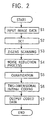
- Fig. 2 is a flowchart illustrating processes performed in the image compression section 8.
- step S1 luminance data and color-difference data serving as image data stored in the storage section 6 are input via the data bus 5.
- the image data is assumed to be data sampled at a 4:2:2 color space of luminance and color differences.
- step S2 DCT (Discrete Cosine Transform) is performed.
- the image data is divided into a block of 8 ⁇ 8 pixels.
- DCT is performed on the divided block.
- DCT is performed in units of 2 blocks for the luminance and 1 block for each of the color differences Cb and Cr.
- step S3 zigzag scanning is performed on the image data of the block in units of 8 ⁇ 8 pixels.
- Fig. 3 for the block in units of 8 ⁇ 8 pixels, by assuming the pixel in the upper left corner to be 0, numbers (coefficients) of 1 through 63 are assigned up to the lower right corner in the order zigzag scanning is performed.
- Coefficient 0 indicates DC components
- coefficients 1 through 63 indicate AC components.
- the image data is converted into a set of zero run lengths and data.
- step S4 a noise reduction process is performed.
- the noise reduction process will be described later.
- step S5 quantization is performed on the image data on which the noise reduction process has been performed.
- the quantization is performed in such a manner that image data on which DCT has been performed is divided by a predetermined coefficient. As a result of the quantization being performed, the entropy of the image data can be lowered.
- step S6 two-dimensional Huffman coding is performed.
- step S7 the image data which has been coded in this manner is output to the recording/playback processing section 9, whereby the data is recorded in a recording medium (not shown).
- noise reduction process performed in step S4 of Fig. 2.
- the noise reduction process with reference to the flowchart shown in Fig. 4 is performed in units of macroblocks.
- reduction of noise is performed by suppressing the high-frequency components of the chroma of the flat portion.
- step S11 initialization is performed by setting a suppress_flag to "1".
- This suppress_flag is a flag indicating whether or not the'high-frequency components of the chroma of the flat portion should be suppressed.
- the suppress_flag has been set to "1”
- the suppress_flag has been set to "0”
- step S12 it is determined whether or not, among the absolute values of the AC coefficients of Y, there is at least one coefficient greater than the threshold value A. As described with reference to Fig. 3, for the AC components of the luminance Y, coefficients 1 through 63 exist. In step S12, all the absolute values of the respective components of the coefficients 1 through 63 of the luminance Y may be compared with the threshold value A. However, it is assumed here that the absolute values of the respective components of the coefficients 1 through 27 of the luminance Y are compared with the threshold value A.
- step S12 the components of the AC coefficients 1 through 27 are sufficient.
- the components of AC coefficients 1 through 63 may be used as the targets of comparison with the threshold value A.
- the threshold value A By decreasing the number of targets of comparison with the threshold value A (by making the low-frequency components among the AC components to be targets), it becomes possible to shorten the processing time required for the noise reduction process. Also, by appropriately selecting the targets of comparison (in this case, the AC coefficients 1 through 27 are selected), it becomes possible to reliably perform a noise reduction process without causing a deterioration in the noise reduction process.
- step S12 When it is determined in step S12 that, among the absolute values of the components of the AC coefficients 1 through 27 of the luminance Y, there is at least one value greater than the threshold value A, the process proceeds to step S13.
- step S13 the suppress_flag is set to "0". That is, in the subsequent processes, the setting is performed so that a suppression process is performed as necessary.
- the suppression refers to components to be processed being set to 0 data.
- the threshold value A is set to a value by which the components within the image of the DCT block can be identified as components formed by the effective edge components of the image or as components formed by the noise components.
- a threshold value C (to be described later) is also set similarly.
- step S14 a process for compressing the DCT block of the luminance Y is performed. Whether or not the process for compressing the DCT block of the luminance Y is terminated is determined in step S15.
- step S15 it is determined whether or not, among the absolute values of the components of the AC components less than the threshold value B of the color difference Cb, there is at least one component of a value greater than the threshold value C.
- the threshold value B is set as a value indicating the boundary between the low-frequency components and the high-frequency components of the color difference Cb (color difference Cr).
- step S17 the suppress_flag is set to "0", that is, the suppress_flag is set so that suppression is not performed in the subsequent processes.
- step S18 it is determined whether or not the suppress_flag is "1". When it is determined that the suppress_flag is "1”, the process proceeds to step S19. Since the suppress_flag is determined to be "1”, in step S19, the components of the AC coefficient greater than the threshold value B of the color difference Cb are suppressed to "0". Then, in step S20, a compression process is performed on the DCT block of the color difference Cb.
- step S18 when it is determined in step S18 that the suppress_flag is not "1", that is, the suppress_flag is "0", or when the suppress_flag is set to "0" in step S17, the process proceeds to step S20, where a compression process is performed on the DCT block of the color difference Cb.
- steps S21 through S25 are processes for the DCT block of the color difference Cr, and basically, these processes are the same as the processes performed on the DCT block of the color difference Cb in steps S16 through S20. Accordingly, an explanation thereof is omitted.
- the same value may be used during the processes for the color difference Cb and the color difference Cr, and different values may also be used.
- the above-described noise reduction process is performed in such a way that the AC components of the luminance Y, in particular, the AC components 1 through 27 positioned in the upper left of the DCT block, the low-frequency components of the color difference Cb (the components of the AC coefficient less than the threshold value B), and the low-frequency components of the color difference Cr (the components of the AC coefficient less than the threshold value B) are made to be detection targets (targets of comparison with the threshold value A or the threshold value C), and is performed in such a way that the high-frequency components of the color difference Cb and the high-frequency components of the color difference Cr are made to be targets of suppression.
- noise generated by the image sensor 2, etc. is eliminated.
- the processes can also be performed by software.
- programs which form the software are installed from a recording medium into a computer incorporated into dedicated hardware or into, for example, a general-purpose personal computer capable of executing various types of functions by installing various programs.
- a recording medium may be formed of a packaged medium in which the program is recorded, which is distributed for providing the program to a user separately from a personal computer, as shown in Fig. 1, such as the magnetic disk 21 (including a floppy (registered trade name) disk), the optical disk 22 (CD-ROM (Compact Disk-Read Only Memory) and a DVD (Digital Versatile Disk)), the magneto-optical disk 23 (including MD (Mini-Disc) (registered trade name)), or the semiconductor memory 24.
- the recording medium may also be formed of a ROM or a hard disk in which the program is recorded, such recording medium being provided to the user while being incorporated in advance in the computer.
- the steps forming the program provided in the form of a recording medium may be executed chronologically according to the written orders. However, they do not have to be executed chronologically, and they may be executed concurrently or individually.
- At least one of the AC components of the luminance data and the AC components of the color-difference data of image data which has been subjected to orthogonal conversion are compared with a threshold value.
- the threshold value When it is determined by the comparison result that components greater than the threshold value do not exist within the AC components, the high-frequency components of the color-difference data are suppressed. Therefore, it is possible to reduce noise components without causing block distortion to occur
Landscapes
- Engineering & Computer Science (AREA)
- Multimedia (AREA)
- Signal Processing (AREA)
- Physics & Mathematics (AREA)
- General Physics & Mathematics (AREA)
- Theoretical Computer Science (AREA)
- Image Processing (AREA)
- Compression Or Coding Systems Of Tv Signals (AREA)
- Facsimile Image Signal Circuits (AREA)
- Color Image Communication Systems (AREA)
- Compression Of Band Width Or Redundancy In Fax (AREA)
- Picture Signal Circuits (AREA)
- Color Television Systems (AREA)
Abstract
Description
- The present invention relates to an image processing apparatus and, more particularly, to an image processing apparatus which is suitably used to eliminate noise components contained in image data.
- As techniques for coding still images and moving images, the JPEG (Joint Photographic Experts Group) technique, the MPEG (Moving Picture Experts Group) technique, and so on are used. For example, in the JPEG technique, a coding process is performed in such a way that a captured still image is divided into a block of 8 × 8 portions, and DCT (Discrete Cosine Transform) processing and quantization processing are performed on that block.
- In the above-described coding process using DCT, there are cases in which, in order to reduce noise, a process for suppressing AC (Alternating Current) coefficients of luminance and color differences is performed. In a case where noise is reduced in such a manner, a problem arises in that block distortion sometimes occurs.
- The present invention has been made in view of such circumstances. An object of the present invention is to reduce noise by comparing noise components and edge components with a threshold value.
- The image processing apparatus of the present invention comprises orthogonal conversion means for performing orthogonal conversion on input image data; comparison means for comparing at least one of AC components of luminance data and AC components of color-difference data of the image data on which orthogonal conversion has been performed by the orthogonal conversion means with a predetermined threshold value; and suppression means for suppressing high-frequency components of the color-difference data when it is determined by the comparison means that components which are greater than the threshold value do not exist within the AC components.
- The comparison means may compare low-frequency components of the AC components of the luminance data with the threshold value.
- The comparison means may compare low-frequency components of the AC components of the color-difference data with the threshold value.
- The orthogonal conversion of the orthogonal conversion means may be DCT.
- The image processing apparatus may comprise a video camera section including image-capturing means.
- The image processing method of the present invention comprises an orthogonal conversion step of performing orthogonal conversion on input image data; a comparison step of comparing at least one of AC components of luminance data and AC components of color-difference data of the image data on which orthogonal conversion has been performed in the process of the orthogonal conversion step with a predetermined threshold value; and a suppression step of suppressing high-frequency components of the color-difference data when it is determined in the process of the comparison step that components which are greater than the threshold value do not exist within the AC components.
- The program of the recording medium of the present invention comprises an orthogonal conversion step of performing orthogonal conversion on input image data; a comparison step of comparing at least one of AC components of luminance data and AC components of color-difference data of the image data on which orthogonal conversion has been performed in the process of the orthogonal conversion step with a predetermined threshold value; and a suppression step of suppressing high-frequency components of the color-difference data when it is determined in the process of the comparison step that components which are greater than the threshold value do not exist within the AC components.
- The program of the present invention allows a computer to execute an orthogonal conversion step of performing orthogonal conversion on input image data; a comparison step of comparing at least one of AC components of luminance data and AC components of color-difference data of the image data on which orthogonal conversion has been performed in the process of the orthogonal conversion step with a predetermined threshold value; and a suppression step of suppressing high-frequency components of the color-difference data when it is determined in the process of the comparison step that components which are greater than the threshold value do not exist within the AC components.
- In the image processing apparatus and method, and the program of the present invention, at least one of the AC components of the luminance data and the AC components of the color-difference data of the image data on which orthogonal conversion is performed are compared with a threshold value. When it is determined by the comparison result that components greater than the threshold value do not exist within the AC components, the high-frequency components of the color-difference data are suppressed.
-
- Fig. 1 shows the configuration of an embodiment of an image processing apparatus to which the present invention is applied.
- Fig. 2 is a flowchart illustrating the operation of an
image compression section 8. - Fig. 3 illustrates zigzag scanning.
- Fig. 4 is a flowchart illustrating details of a noise reduction process performed in step S4 of Fig. 2.
- An embodiment of the present invention will now be described below with reference to the drawings. Fig. 1 shows the configuration of an embodiment of an image processing apparatus to which the present invention is applied. The
image processing apparatus 1 is an apparatus for handling, for example, still images and moving images for a digital still camera, a digital video camera, a camcorder, etc. Image data of an image captured by animage sensor 2 of theimage processing apparatus 1 is output to adata processing section 3. Theimage sensor 2 is driven by adriving section 4. - The
data processing section 3 generates luminance data and color-difference data from the input image data, and outputs the data to astorage section 6 via adata bus 5. Thestorage section 6 temporarily stores the luminance data and the color-difference data. The luminance data and the color-difference data stored in thestorage section 6 are output to afilter 7. Thefilter 7 performs a process for conversion into a resolution of a desired image size on the input luminance data and color-difference data, and causes the data to be stored again in thestorage section 6. - The luminance data and the color-difference data whose resolutions are converted, stored in the
storage section 6, are output to animage compression section 8, whereby a compression process is performed. The luminance data and the color-difference data on which a coding process has been performed are recorded on a recording medium (not shown) by a recording/playback processing section 9. Such a recording process is performed when ashutter button 10 is operated, and a process corresponding to that operation is instructed from amicrocomputer 11. - A
drive 12 is used when data is read from or written into a recording medium, such as amagnetic disk 21, anoptical disk 22, a magneto-optical disk 23, or asemiconductor memory 24. - Fig. 2 is a flowchart illustrating processes performed in the
image compression section 8. In step S1, luminance data and color-difference data serving as image data stored in thestorage section 6 are input via thedata bus 5. In the following description, the image data is assumed to be data sampled at a 4:2:2 color space of luminance and color differences. - In step S2, DCT (Discrete Cosine Transform) is performed. First, the image data is divided into a block of 8 × 8 pixels. DCT is performed on the divided block. In this case, since a 4:2:2 color space is used, DCT is performed in units of 2 blocks for the luminance and 1 block for each of the color differences Cb and Cr.
- In step S3, zigzag scanning is performed on the image data of the block in units of 8 × 8 pixels. As shown in Fig. 3, for the block in units of 8 × 8 pixels, by assuming the pixel in the upper left corner to be 0, numbers (coefficients) of 1 through 63 are assigned up to the lower right corner in the order zigzag scanning is performed.
Coefficient 0 indicates DC components, andcoefficients 1 through 63 indicate AC components. As a result of the zigzag scanning being performed on the AC components, the image data is converted into a set of zero run lengths and data. - In step S4, a noise reduction process is performed. The noise reduction process will be described later. In step S5, quantization is performed on the image data on which the noise reduction process has been performed. The quantization is performed in such a manner that image data on which DCT has been performed is divided by a predetermined coefficient. As a result of the quantization being performed, the entropy of the image data can be lowered. Then, in step S6, two-dimensional Huffman coding is performed.
- In step S7, the image data which has been coded in this manner is output to the recording/
playback processing section 9, whereby the data is recorded in a recording medium (not shown). - Referring to the flowchart in Fig. 4, a description will now be given of the noise reduction process performed in step S4 of Fig. 2. The noise reduction process with reference to the flowchart shown in Fig. 4 is performed in units of macroblocks. In this embodiment, reduction of noise is performed by suppressing the high-frequency components of the chroma of the flat portion.
- In step S11, initialization is performed by setting a suppress_flag to "1". This suppress_flag is a flag indicating whether or not the'high-frequency components of the chroma of the flat portion should be suppressed. When the suppress_flag has been set to "1", this means that suppression is to be performed. When the suppress_flag has been set to "0", this means that suppression is not to be performed.
- In step S12, it is determined whether or not, among the absolute values of the AC coefficients of Y, there is at least one coefficient greater than the threshold value A. As described with reference to Fig. 3, for the AC components of the luminance Y,
coefficients 1 through 63 exist. In step S12, all the absolute values of the respective components of thecoefficients 1 through 63 of the luminance Y may be compared with the threshold value A. However, it is assumed here that the absolute values of the respective components of thecoefficients 1 through 27 of the luminance Y are compared with the threshold value A. - The reason for the above is that, even if the components are of a small amplitude, when edge components of a certain image are contained in the block after DCT processing, since the possibility that a large part of components appears in certain components of the
AC coefficients 1 through 27 is high, it can be considered in step S12 that, as the targets of comparison with the threshold value A, the components of theAC coefficients 1 through 27 are sufficient. Of course, the components ofAC coefficients 1 through 63 may be used as the targets of comparison with the threshold value A. - As discussed above, by decreasing the number of targets of comparison with the threshold value A (by making the low-frequency components among the AC components to be targets), it becomes possible to shorten the processing time required for the noise reduction process. Also, by appropriately selecting the targets of comparison (in this case, the
AC coefficients 1 through 27 are selected), it becomes possible to reliably perform a noise reduction process without causing a deterioration in the noise reduction process. - When it is determined in step S12 that, among the absolute values of the components of the
AC coefficients 1 through 27 of the luminance Y, there is at least one value greater than the threshold value A, the process proceeds to step S13. When it is determined that there is no value greater than the threshold value A, the process of step S13 is skipped, and the process proceeds to step S14. In step S13, the suppress_flag is set to "0". That is, in the subsequent processes, the setting is performed so that a suppression process is performed as necessary. The suppression refers to components to be processed being set to 0 data. - When it is determined that, among the absolute values of the components of the
AC coefficients 1 through 27 of the luminance Y, there is at least one value greater than the threshold value A and the suppress_flag is set to "0", it can be determined that edge components of a certain image are contained in the image of the DCT block to be processed. However, even when effective edge components of the image are not contained, noise components of a small amplitude are output from, for example, the image-capturing device of the image sensor 2 (Fig. 1), and the noise components may exert an influence on the components of the luminance Y. - By considering the above, the threshold value A is set to a value by which the components within the image of the DCT block can be identified as components formed by the effective edge components of the image or as components formed by the noise components. A threshold value C (to be described later) is also set similarly.
- In step S14, a process for compressing the DCT block of the luminance Y is performed. Whether or not the process for compressing the DCT block of the luminance Y is terminated is determined in step S15.
- When a macroblock of a 4:2:2 image is to be processed, there are two DCT blocks of the luminance Y, and therefore, processes of steps S12 through S15 are repeated two times. When it is determined in step S15 that the process for compressing the DCT block of the luminance Y is terminated, the process proceeds to step S16. In step S16, it is determined whether or not, among the absolute values of the components of the AC components less than the threshold value B of the color difference Cb, there is at least one component of a value greater than the threshold value C.
- The threshold value B is set as a value indicating the boundary between the low-frequency components and the high-frequency components of the color difference Cb (color difference Cr). When it is determined in step S16 that, among the absolute values of the AC components of the color difference Cb less than the set threshold value B, there are components of the AC coefficient of a value greater than the threshold value C, the process proceeds to step S17. When it is determined that there are no such components, the process proceeds to step S18.
- In step S17, the suppress_flag is set to "0", that is, the suppress_flag is set so that suppression is not performed in the subsequent processes. In step S18, it is determined whether or not the suppress_flag is "1". When it is determined that the suppress_flag is "1", the process proceeds to step S19. Since the suppress_flag is determined to be "1", in step S19, the components of the AC coefficient greater than the threshold value B of the color difference Cb are suppressed to "0". Then, in step S20, a compression process is performed on the DCT block of the color difference Cb.
- On the other hand, when it is determined in step S18 that the suppress_flag is not "1", that is, the suppress_flag is "0", or when the suppress_flag is set to "0" in step S17, the process proceeds to step S20, where a compression process is performed on the DCT block of the color difference Cb.
- When the compression process for the DCT block of the color difference Cb in step S20 is terminated, the process proceeds to step S21. The processes of steps S21 through S25 are processes for the DCT block of the color difference Cr, and basically, these processes are the same as the processes performed on the DCT block of the color difference Cb in steps S16 through S20. Accordingly, an explanation thereof is omitted.
- For the threshold value B and the threshold value C, the same value may be used during the processes for the color difference Cb and the color difference Cr, and different values may also be used.
- The above-described noise reduction process is performed in such a way that the AC components of the luminance Y, in particular, the
AC components 1 through 27 positioned in the upper left of the DCT block, the low-frequency components of the color difference Cb (the components of the AC coefficient less than the threshold value B), and the low-frequency components of the color difference Cr (the components of the AC coefficient less than the threshold value B) are made to be detection targets (targets of comparison with the threshold value A or the threshold value C), and is performed in such a way that the high-frequency components of the color difference Cb and the high-frequency components of the color difference Cr are made to be targets of suppression. As a result, noise generated by theimage sensor 2, etc., is eliminated. - As a result of the above, it is possible to prevent effective edge components of the image from being determined to be noise and from being suppressed, conversely, it is possible to prevent noise from being determined to be effective edge components of the image and from being not suppressed. Thus, it is possible to reliably leave the edge components of the image and to eliminate unwanted noise.
- In the above-described embodiment, the case of image data which is sampled at a 4:2:2 color space has been described as an example. Of course, the present invention can be applied to a 4:2:0 color space and a 4:1:1 color space.
- Although the above-described series of processes can be performed by hardware, the processes can also be performed by software. In a case where the series of processes is performed by software, programs which form the software are installed from a recording medium into a computer incorporated into dedicated hardware or into, for example, a general-purpose personal computer capable of executing various types of functions by installing various programs.
- A recording medium may be formed of a packaged medium in which the program is recorded, which is distributed for providing the program to a user separately from a personal computer, as shown in Fig. 1, such as the magnetic disk 21 (including a floppy (registered trade name) disk), the optical disk 22 (CD-ROM (Compact Disk-Read Only Memory) and a DVD (Digital Versatile Disk)), the magneto-optical disk 23 (including MD (Mini-Disc) (registered trade name)), or the
semiconductor memory 24. The recording medium may also be formed of a ROM or a hard disk in which the program is recorded, such recording medium being provided to the user while being incorporated in advance in the computer. - In this specification, the steps forming the program provided in the form of a recording medium may be executed chronologically according to the written orders. However, they do not have to be executed chronologically, and they may be executed concurrently or individually.
- As has thus been described, according to the image processing apparatus and method, and the program of the present invention, at least one of the AC components of the luminance data and the AC components of the color-difference data of image data which has been subjected to orthogonal conversion are compared with a threshold value. When it is determined by the comparison result that components greater than the threshold value do not exist within the AC components, the high-frequency components of the color-difference data are suppressed. Therefore, it is possible to reduce noise components without causing block distortion to occur
Claims (8)
- An image processing apparatus comprising:orthogonal conversion means for performing orthogonal conversion on input image data;comparison means for comparing at least one of AC components of luminance data and AC components of color-difference data of said image data on which orthogonal conversion has been performed by said orthogonal conversion means with a predetermined threshold value; andsuppression means for suppressing high-frequency components of said color-difference data when it is determined by said comparison means that components which are greater than said threshold value do not exist within said AC components.
- An image processing apparatus according to Claim 1, wherein said comparison means compares low-frequency components of the AC components of said luminance data with said threshold value.
- An image processing apparatus according to Claim 1, wherein said comparison means compares low-frequency components of the AC components of said color-difference data with said threshold value.
- An image processing apparatus according to Claim 1, wherein said orthogonal conversion of said orthogonal conversion means is DCT.
- An image processing apparatus according to Claim 1, wherein said image processing apparatus comprises a video camera section including image-capturing means.
- An image processing method comprising:an orthogonal conversion step of performing orthogonal conversion on input image data;a comparison step of comparing at least one of AC components of luminance data and AC components of color-difference data of said image data on which orthogonal conversion has been performed in the process of said orthogonal conversion step with a predetermined threshold value; anda suppression step of suppressing high-frequency components of said color-difference data when it is determined in the process of said comparison step that components which are greater than said threshold value do not exist within said AC components.
- A recording medium having recorded thereon a computer-readable program, said program comprising:an orthogonal conversion step of performing orthogonal conversion on input image data;a comparison step of comparing at least one of AC components of luminance data and AC components of color-difference data of said image data on which orthogonal conversion has been performed in the process of said orthogonal conversion step with a predetermined threshold value; anda suppression step of suppressing high-frequency components of said color-difference data when it is determined in the process of said comparison step that components which are greater than said threshold value do not exist within said AC components.
- A program for allowing a computer to execute:an orthogonal conversion step of performing orthogonal conversion on input image data;a comparison step of comparing at least one of AC components of luminance data and AC components of color-difference data of said image data on which orthogonal conversion has been performed in the process of said orthogonal conversion step with a predetermined threshold value; anda suppression step of suppressing high-frequency components of said color-difference data when it is determined in the process of said comparison step that components which are greater than said threshold value do not exist within said AC components.
Applications Claiming Priority (3)
| Application Number | Priority Date | Filing Date | Title |
|---|---|---|---|
| JP2001150891A JP3791003B2 (en) | 2001-05-21 | 2001-05-21 | Image processing apparatus and method, recording medium, and program |
| JP2001150891 | 2001-05-21 | ||
| PCT/JP2002/004308 WO2002096092A1 (en) | 2001-05-21 | 2002-04-30 | Image processor |
Publications (3)
| Publication Number | Publication Date |
|---|---|
| EP1404115A1 true EP1404115A1 (en) | 2004-03-31 |
| EP1404115A4 EP1404115A4 (en) | 2006-09-06 |
| EP1404115B1 EP1404115B1 (en) | 2010-01-20 |
Family
ID=18995838
Family Applications (1)
| Application Number | Title | Priority Date | Filing Date |
|---|---|---|---|
| EP20020722890 Expired - Lifetime EP1404115B1 (en) | 2001-05-21 | 2002-04-30 | Image processor |
Country Status (8)
| Country | Link |
|---|---|
| US (1) | US7187714B2 (en) |
| EP (1) | EP1404115B1 (en) |
| JP (1) | JP3791003B2 (en) |
| KR (1) | KR100897644B1 (en) |
| CN (1) | CN1199436C (en) |
| DE (1) | DE60235163D1 (en) |
| TW (1) | TW573431B (en) |
| WO (1) | WO2002096092A1 (en) |
Families Citing this family (16)
| Publication number | Priority date | Publication date | Assignee | Title |
|---|---|---|---|---|
| US6928186B2 (en) * | 2002-06-21 | 2005-08-09 | Seiko Epson Corporation | Semantic downscaling and cropping (SEDOC) of digital images |
| CN100362850C (en) * | 2005-01-17 | 2008-01-16 | 深圳创维-Rgb电子有限公司 | TV Image Edge Enhancement Method |
| US8179836B2 (en) * | 2005-04-20 | 2012-05-15 | Interdigital Technology Corporation | Method and apparatus for controlling transmissions via an enhanced dedicated channel |
| JP4302661B2 (en) * | 2005-05-02 | 2009-07-29 | 富士通マイクロエレクトロニクス株式会社 | Image processing system |
| JP4410225B2 (en) * | 2006-08-07 | 2010-02-03 | 株式会社東芝 | Moving picture decoding apparatus and method |
| US20080136654A1 (en) * | 2006-12-12 | 2008-06-12 | Motorola, Inc. | Methods and devices for power source life value calculation and representation |
| US8326075B2 (en) | 2008-09-11 | 2012-12-04 | Google Inc. | System and method for video encoding using adaptive loop filter |
| US8885706B2 (en) | 2011-09-16 | 2014-11-11 | Google Inc. | Apparatus and methodology for a video codec system with noise reduction capability |
| US9131073B1 (en) | 2012-03-02 | 2015-09-08 | Google Inc. | Motion estimation aided noise reduction |
| US9344729B1 (en) | 2012-07-11 | 2016-05-17 | Google Inc. | Selective prediction signal filtering |
| CN102801983A (en) * | 2012-08-29 | 2012-11-28 | 上海国茂数字技术有限公司 | Denoising method and device on basis of DCT (Discrete Cosine Transform) |
| US9998750B2 (en) * | 2013-03-15 | 2018-06-12 | Cisco Technology, Inc. | Systems and methods for guided conversion of video from a first to a second compression format |
| CN105011301A (en) * | 2014-04-18 | 2015-11-04 | 天津市恒安食品有限公司 | Oat coarse grain beverage and preparation process thereof |
| CN105011299A (en) * | 2014-04-18 | 2015-11-04 | 天津市恒安食品有限公司 | Corn beverage and preparation method thereof |
| US10102613B2 (en) | 2014-09-25 | 2018-10-16 | Google Llc | Frequency-domain denoising |
| CN108305222B (en) * | 2018-01-04 | 2020-08-04 | 浙江大华技术股份有限公司 | Image noise reduction method and device, electronic equipment and storage medium |
Family Cites Families (10)
| Publication number | Priority date | Publication date | Assignee | Title |
|---|---|---|---|---|
| FR2621194B1 (en) * | 1987-09-29 | 1989-12-29 | Labo Electronique Physique | DEVICE FOR CODING DIGITAL VIDEO SIGNALS |
| JP3081658B2 (en) * | 1991-04-10 | 2000-08-28 | オリンパス光学工業株式会社 | Image signal encoding device and image signal decoding device |
| JPH0514739A (en) * | 1991-07-02 | 1993-01-22 | Sony Corp | Picture encoding device |
| JPH0670175A (en) | 1992-08-19 | 1994-03-11 | Fujitsu Ltd | Method and device for encoding picture data |
| JPH0774959A (en) | 1993-09-02 | 1995-03-17 | Canon Inc | Image processing device |
| JPH07322259A (en) | 1994-05-20 | 1995-12-08 | Canon Inc | Image processing device |
| US5719961A (en) * | 1994-07-22 | 1998-02-17 | Apple Computer, Inc. | Adaptive technique for encoder and decoder signal transformation |
| TW279298B (en) * | 1994-11-24 | 1996-06-21 | Victor Company Of Japan | |
| TW293227B (en) * | 1994-11-24 | 1996-12-11 | Victor Company Of Japan | |
| KR20000050286A (en) * | 1999-01-02 | 2000-08-05 | 윤종용 | Method for reducing blocking effect in decoded image |
-
2001
- 2001-05-21 JP JP2001150891A patent/JP3791003B2/en not_active Expired - Fee Related
-
2002
- 2002-04-30 KR KR20037000841A patent/KR100897644B1/en not_active Expired - Fee Related
- 2002-04-30 US US10/333,509 patent/US7187714B2/en not_active Expired - Fee Related
- 2002-04-30 DE DE60235163T patent/DE60235163D1/en not_active Expired - Lifetime
- 2002-04-30 EP EP20020722890 patent/EP1404115B1/en not_active Expired - Lifetime
- 2002-04-30 WO PCT/JP2002/004308 patent/WO2002096092A1/en not_active Ceased
- 2002-04-30 CN CNB028019350A patent/CN1199436C/en not_active Expired - Fee Related
- 2002-05-20 TW TW91110531A patent/TW573431B/en not_active IP Right Cessation
Also Published As
| Publication number | Publication date |
|---|---|
| WO2002096092A1 (en) | 2002-11-28 |
| US20040047416A1 (en) | 2004-03-11 |
| CN1463531A (en) | 2003-12-24 |
| CN1199436C (en) | 2005-04-27 |
| US7187714B2 (en) | 2007-03-06 |
| JP3791003B2 (en) | 2006-06-28 |
| KR20030026982A (en) | 2003-04-03 |
| EP1404115B1 (en) | 2010-01-20 |
| EP1404115A4 (en) | 2006-09-06 |
| JP2002344749A (en) | 2002-11-29 |
| KR100897644B1 (en) | 2009-05-14 |
| DE60235163D1 (en) | 2010-03-11 |
| TW573431B (en) | 2004-01-21 |
Similar Documents
| Publication | Publication Date | Title |
|---|---|---|
| US7187714B2 (en) | Image processing apparatus for suppressing high-frequency components of color difference data | |
| EP1246131B1 (en) | Method and apparatus for the reduction of artifact in decompressed images using post-filtering | |
| JP5261376B2 (en) | Image coding apparatus and image decoding apparatus | |
| US20080198932A1 (en) | Complexity-based rate control using adaptive prefilter | |
| WO2002067589A1 (en) | Image processing system, image processing method, and image processing program | |
| JPH08251422A (en) | Block distortion corrector and image signal expansion device | |
| US8135231B2 (en) | Image processing method and device for performing mosquito noise reduction | |
| CN1717053A (en) | Be used to eliminate filter and method thereof based on the discontinuity of the image of block encoding | |
| JPH05308623A (en) | Image signal decoder | |
| US20060126729A1 (en) | Image encoding apparatus and method thereof | |
| JP2004215216A (en) | Image processing apparatus, image processing method, and image processing program | |
| EP1777967B1 (en) | Filtering apparatus, method, and medium for multi-format codec | |
| CN1964491A (en) | Dynamic video coding device and image recording/reproducing device | |
| JP2007251881A (en) | Block noise eliminating apparatus, and electronic appliance | |
| JP4239231B2 (en) | Block distortion reducing apparatus and method | |
| CA2310652C (en) | Partial decoding of compressed video sequences | |
| JP4196929B2 (en) | Noise detection apparatus and noise detection program | |
| JP4232733B2 (en) | Noise reduction method | |
| JP2985752B2 (en) | Video decoding device | |
| JPH06311499A (en) | Picture signal decoding device | |
| JP2000299860A (en) | Image decoding device | |
| JP2000299859A (en) | Image decoding device | |
| JP2002232896A (en) | Image encoding device and image encoding program | |
| JPH10304352A (en) | Coding noise removal apparatus and coding noise removal method | |
| HK1153596B (en) | Method and apparatus for controlling loop filtering or post filtering in block based motion compensated video coding |
Legal Events
| Date | Code | Title | Description |
|---|---|---|---|
| PUAI | Public reference made under article 153(3) epc to a published international application that has entered the european phase |
Free format text: ORIGINAL CODE: 0009012 |
|
| 17P | Request for examination filed |
Effective date: 20030113 |
|
| AK | Designated contracting states |
Kind code of ref document: A1 Designated state(s): AT BE CH CY DE DK ES FI FR GB GR IE IT LI LU MC NL PT SE TR |
|
| A4 | Supplementary search report drawn up and despatched |
Effective date: 20060809 |
|
| 17Q | First examination report despatched |
Effective date: 20061017 |
|
| GRAP | Despatch of communication of intention to grant a patent |
Free format text: ORIGINAL CODE: EPIDOSNIGR1 |
|
| GRAS | Grant fee paid |
Free format text: ORIGINAL CODE: EPIDOSNIGR3 |
|
| GRAA | (expected) grant |
Free format text: ORIGINAL CODE: 0009210 |
|
| AK | Designated contracting states |
Kind code of ref document: B1 Designated state(s): DE FR GB |
|
| REG | Reference to a national code |
Ref country code: GB Ref legal event code: FG4D |
|
| REF | Corresponds to: |
Ref document number: 60235163 Country of ref document: DE Date of ref document: 20100311 Kind code of ref document: P |
|
| PLBE | No opposition filed within time limit |
Free format text: ORIGINAL CODE: 0009261 |
|
| STAA | Information on the status of an ep patent application or granted ep patent |
Free format text: STATUS: NO OPPOSITION FILED WITHIN TIME LIMIT |
|
| 26N | No opposition filed |
Effective date: 20101021 |
|
| PGFP | Annual fee paid to national office [announced via postgrant information from national office to epo] |
Ref country code: FR Payment date: 20110510 Year of fee payment: 10 Ref country code: DE Payment date: 20110421 Year of fee payment: 10 |
|
| PGFP | Annual fee paid to national office [announced via postgrant information from national office to epo] |
Ref country code: GB Payment date: 20110421 Year of fee payment: 10 |
|
| GBPC | Gb: european patent ceased through non-payment of renewal fee |
Effective date: 20120430 |
|
| REG | Reference to a national code |
Ref country code: FR Ref legal event code: ST Effective date: 20121228 |
|
| PG25 | Lapsed in a contracting state [announced via postgrant information from national office to epo] |
Ref country code: GB Free format text: LAPSE BECAUSE OF NON-PAYMENT OF DUE FEES Effective date: 20120430 |
|
| REG | Reference to a national code |
Ref country code: DE Ref legal event code: R119 Ref document number: 60235163 Country of ref document: DE Effective date: 20121101 |
|
| PG25 | Lapsed in a contracting state [announced via postgrant information from national office to epo] |
Ref country code: FR Free format text: LAPSE BECAUSE OF NON-PAYMENT OF DUE FEES Effective date: 20120430 |
|
| PG25 | Lapsed in a contracting state [announced via postgrant information from national office to epo] |
Ref country code: DE Free format text: LAPSE BECAUSE OF NON-PAYMENT OF DUE FEES Effective date: 20121101 |