EP1403862A2 - Tape recording/reproducing apparatus - Google Patents
Tape recording/reproducing apparatus Download PDFInfo
- Publication number
- EP1403862A2 EP1403862A2 EP03255818A EP03255818A EP1403862A2 EP 1403862 A2 EP1403862 A2 EP 1403862A2 EP 03255818 A EP03255818 A EP 03255818A EP 03255818 A EP03255818 A EP 03255818A EP 1403862 A2 EP1403862 A2 EP 1403862A2
- Authority
- EP
- European Patent Office
- Prior art keywords
- pcb
- main
- capstan motor
- connector
- main base
- Prior art date
- Legal status (The legal status is an assumption and is not a legal conclusion. Google has not performed a legal analysis and makes no representation as to the accuracy of the status listed.)
- Withdrawn
Links
Images



Classifications
-
- G—PHYSICS
- G11—INFORMATION STORAGE
- G11B—INFORMATION STORAGE BASED ON RELATIVE MOVEMENT BETWEEN RECORD CARRIER AND TRANSDUCER
- G11B33/00—Constructional parts, details or accessories not provided for in the other groups of this subclass
- G11B33/12—Disposition of constructional parts in the apparatus, e.g. of power supply, of modules
- G11B33/121—Disposition of constructional parts in the apparatus, e.g. of power supply, of modules the apparatus comprising a single recording/reproducing device
-
- G—PHYSICS
- G11—INFORMATION STORAGE
- G11B—INFORMATION STORAGE BASED ON RELATIVE MOVEMENT BETWEEN RECORD CARRIER AND TRANSDUCER
- G11B15/00—Driving, starting or stopping record carriers of filamentary or web form; Driving both such record carriers and heads; Guiding such record carriers or containers therefor; Control thereof; Control of operating function
- G11B15/18—Driving; Starting; Stopping; Arrangements for control or regulation thereof
- G11B15/26—Driving record carriers by members acting directly or indirectly thereon
-
- G—PHYSICS
- G11—INFORMATION STORAGE
- G11B—INFORMATION STORAGE BASED ON RELATIVE MOVEMENT BETWEEN RECORD CARRIER AND TRANSDUCER
- G11B15/00—Driving, starting or stopping record carriers of filamentary or web form; Driving both such record carriers and heads; Guiding such record carriers or containers therefor; Control thereof; Control of operating function
- G11B15/18—Driving; Starting; Stopping; Arrangements for control or regulation thereof
- G11B15/26—Driving record carriers by members acting directly or indirectly thereon
- G11B15/28—Driving record carriers by members acting directly or indirectly thereon through rollers driving by frictional contact with the record carrier, e.g. capstan; Multiple arrangements of capstans or drums coupled to means for controlling the speed of the drive; Multiple capstan systems alternately engageable with record carrier to provide reversal
-
- G—PHYSICS
- G11—INFORMATION STORAGE
- G11B—INFORMATION STORAGE BASED ON RELATIVE MOVEMENT BETWEEN RECORD CARRIER AND TRANSDUCER
- G11B15/00—Driving, starting or stopping record carriers of filamentary or web form; Driving both such record carriers and heads; Guiding such record carriers or containers therefor; Control thereof; Control of operating function
- G11B15/18—Driving; Starting; Stopping; Arrangements for control or regulation thereof
- G11B15/44—Speed-changing arrangements; Reversing arrangements; Drive transfer means therefor
-
- G—PHYSICS
- G11—INFORMATION STORAGE
- G11B—INFORMATION STORAGE BASED ON RELATIVE MOVEMENT BETWEEN RECORD CARRIER AND TRANSDUCER
- G11B33/00—Constructional parts, details or accessories not provided for in the other groups of this subclass
- G11B33/12—Disposition of constructional parts in the apparatus, e.g. of power supply, of modules
- G11B33/121—Disposition of constructional parts in the apparatus, e.g. of power supply, of modules the apparatus comprising a single recording/reproducing device
- G11B33/122—Arrangements for providing electrical connections, e.g. connectors, cables, switches
Definitions
- the present invention relates to a tape recording/reproducing apparatus comprising first and second circuit boards, and a capstan motor mounted such that its spindle projects through the first circuit board away from the second circuit board and having a body substantially on one side of the first circuit board.
- Tape recorders such as a VCRs, are well known devices.
- a typical tape recorder is provided with driving motors of various types, for example, a head drum motor, a tape loading motor, a reel motor and a capstan motor.
- FIG 1 is a partial schematic perspective view showing a conventional connection structure of a main base 10 and a capstan motor 30 in a tape recorder.
- the capstan motor 30, which is disposed to run a videotape at a constant velocity, includes a sub PCB 40 having a velocity controlling circuit, as it is necessary to precisely control the rotation of the capstan motor 30.
- the capstan motor 30 is electrically connected to a main PCB 20 of a tape recorder using a connector 41 mounted on the sub PCB 40.
- a capstan motor connection structure of a conventional tape recorder is structured in a manner such that the connector 41 disposed on the sub PCB 40 of the capstan motor 30 is directly connected to a connector holder 21 disposed on the main PCB 20 of a tape recorder as the capstan motor 30 is connected to the main PCB 20 in the main base 10 of the deck.
- the conventional tape recorder is also provided with an outer case 1, a tape cassette 2 and a head drum 3, which are not described in any further detail.
- the connector 41 and the connector holder 21 respectively protrude from the sub PCB 40 and the main PCB 20 with predetermined heights. Accordingly, there is a need for a space to exist to allow for the connection of the connector 41 to the connector holder 21. Also, the main base 10, the main PCB 20, and the sub PCB 40 have to be positioned to maintain predetermined distances between the main base 10 and the main PCB 20, and between the main PCB 20 and the sub PCB 40 so as to allow a space for a body of the capstan motor 30 having a predetermined thickness.
- the main base 10, the main PCB 20 and the sub PCB 40 of the conventional tape recorder are disposed to have a distance 'x' of 17.3mm between the main base 10 and the main PCB 20 and a distance 'y' of 14.7mm between the main PCB 20 and the sub PCB 40.
- the capstan motor connection structure of the conventional tape recorder is limited in the amount by which the overall height of the tape recorder can be reduced due to the direct connection structure of the connector holder 21 and the connector 41, which are respectively disposed on the main PCB 20 and the sub PCB 40, and because the spaces for the body of the capstan motor 30 having the predetermined thickness are limited to the distances 'x' between the main base 10 and the main PCB 20 and the distance 'y' between the main PCB 20 and the sub PCB 40.
- an object of the present invention is to provide a tape recorder having an improved connection structure of a sub PCB of a capstan motor and a main PCB, thereby reducing the overall height of the tape recorder.
- the above object and other object are substantially achieved by providing a capstan motor connection structure of a tape recorder for electrically connecting a main PCB disposed in a parallel or substantially parallel relation to a main base of a deck of the tape recorder to a sub PCB of a capstan motor disposed on the main base.
- the capstan motor connection structure comprises a first connector disposed at the main PCB to be electrically connected thereto, a second connector disposed at an end of the main base to be electrically connected to the first connector, a supporting hole formed in the main base, and a cable penetratingly supported in the supporting hole of the main base, for electrically connecting the sub PCB of the capstan motor to the second connector.
- the capstan motor is positioned such that its body is placed in a hole formed in the main PCB, to thus reduce a distance between the main base and the main PCB.
- a tape recorder including a capstan motor having a sub PCB electrically connected to a main PCB disposed in a parallel or substantially parallel relation to a main base of a deck.
- a connection structure of the capstan motor for connecting the sub PCB to the main PCB comprises a first connector disposed at the main PCB to be electrically connected thereto, a second connector disposed at a side end of the main base corresponding to the first connector to be electrically connected to the first connector, a supporting hole formed in the main base, and a cable penetratingly supported in the supporting hole of the main base, for electrically connecting the sub PCB wafer of the capstan motor to the second connector.
- the capstan motor is positioned such that its body is placed in a hole formed in the main PCB, to thus reduce a distance between the main base and the main PCB.
- one end of the cable is electrically connected to a circuit pattern of the sub PCB by soldering.
- first and the second connectors are disposed to a side edge of the main base to be connected to each other.
- the distance between the main base and the main PCB is at or about 10 ⁇ 1 mm
- a distance between the main PCB and the sub PCB is at or about 7.5 ⁇ 0.5 mm.
- an embodiment of a tape recorder 100 having a capstan motor connection structure includes a first connector 121 electrically connected to a main PCB 120, a second connector 111 disposed adjacent to one side of a main base 110 for being electrically connected to the first connector 121, a through hole (or supporting hole) 110a formed in the main base 110 and a cable 150, for electrically connecting a sub PCB 140 of the capstan motor 130 to the second connector 111, which passes through the through hole 110a such that it is supported by the main PCB 120.
- the main PCB 120 has a hole 120a formed therein.
- the capstan motor 130 is "built-in" with respect to the main PCB 120 with its body 131 being placed in the hole 120a such that a distance 'X' between the main base 110 and the main PCB 120 is reduced.
- the tape recorder 100 is also provided with an outer case 101, a tape cassette 2 and a head drum 3.
- this embodiment of the present invention solves the problem of the space restriction that is caused by the direct connection of the connector 41 and the connector holder 21 in the conventional tape recorder and the requirement for the space for the body of the capstan motor 30 having the predetermined thickness, the overall height of the tape recorder can be reduced.
- the above-described embodiment of the capstan motor connection structure according to the present invention has the hole 120a formed in the main PCB 120 for allowing the capstan motor 130 to be built into the main PCB 120, with its body 131 being placed in the hole 120a. Accordingly, the main PCB 120 is disposed nearer to a bottom of the main base 110 such that the distance 'X' between the main base 110 and the main PCB 120 is reduced.
- one end of the cable 150 is connected to a circuit pattern of the sub PCB 140 by soldering, and the other end is passed through the through hole 110a formed in the main base 110 and is then connected to the second connector 111 disposed at the end of the main base 110.
- the cable 150 could be a ribbon-type cable such as a flexible printed circuit (FPC).
- the second connector 111 is connected to the first connector 121 disposed on the main PCB 120, so that the space restriction caused by the change of connection position of the connector and the connector holder in the conventional tape recorder can be solved. Accordingly, the distance 'Y' between the main PCB 120 and the sub PCB 140 can be reduced.
- the outer case 101 of the tape recorder 100 has a recess 101 a formed in the bottom thereof.
- the recess 101 receives a head of the capstan motor 130, thereby reducing the overall height of the tape recorder.
- the distance 'X' between the main base 110 and the main PCB 120 is actually or about 10 ⁇ 1 mm .
- the distance 'Y' between the main PCB 120 and the sub PCB 140 is actually or about 7.5 ⁇ 0.5 mm .
- the distance 'X' between the main base 110 and the main PCB 120 is reduced by as much as or about 7.3 ⁇ 1 mm compared to the conventional capstan motor connection structure.
- the distance 'Y' between the main PCB 120 and the sub PCB 140 is reduced by as much as or about 7.2 ⁇ 0.5 mm compared to the conventional capstan motor connection structure, thus the entire height of the tape recorder is lowered and slimmed.
- the overall height of the tape recorder can be reduced.
Landscapes
- Motor Or Generator Frames (AREA)
- Coupling Device And Connection With Printed Circuit (AREA)
- Recording Or Reproducing By Magnetic Means (AREA)
Abstract
Description
- The present invention relates to a tape recording/reproducing apparatus comprising first and second circuit boards, and a capstan motor mounted such that its spindle projects through the first circuit board away from the second circuit board and having a body substantially on one side of the first circuit board.
- Tape recorders, such as a VCRs, are well known devices. A typical tape recorder is provided with driving motors of various types, for example, a head drum motor, a tape loading motor, a reel motor and a capstan motor.
- Figure 1 is a partial schematic perspective view showing a conventional connection structure of a
main base 10 and acapstan motor 30 in a tape recorder. Referring to Figure 1, thecapstan motor 30, which is disposed to run a videotape at a constant velocity, includes asub PCB 40 having a velocity controlling circuit, as it is necessary to precisely control the rotation of thecapstan motor 30. Thecapstan motor 30 is electrically connected to amain PCB 20 of a tape recorder using aconnector 41 mounted on thesub PCB 40. - A capstan motor connection structure of a conventional tape recorder, as shown in Figure 2, is structured in a manner such that the
connector 41 disposed on thesub PCB 40 of thecapstan motor 30 is directly connected to aconnector holder 21 disposed on themain PCB 20 of a tape recorder as thecapstan motor 30 is connected to themain PCB 20 in themain base 10 of the deck. Referring to Figure 2, the conventional tape recorder is also provided with an outer case 1, atape cassette 2 and ahead drum 3, which are not described in any further detail. - In the case of the conventional capstan motor connection structure as described above, the
connector 41 and theconnector holder 21 respectively protrude from thesub PCB 40 and themain PCB 20 with predetermined heights. Accordingly, there is a need for a space to exist to allow for the connection of theconnector 41 to theconnector holder 21. Also, themain base 10, themain PCB 20, and thesub PCB 40 have to be positioned to maintain predetermined distances between themain base 10 and themain PCB 20, and between themain PCB 20 and thesub PCB 40 so as to allow a space for a body of thecapstan motor 30 having a predetermined thickness. In this particular arrangement, themain base 10, themain PCB 20 and thesub PCB 40 of the conventional tape recorder are disposed to have a distance 'x' of 17.3mm between themain base 10 and themain PCB 20 and a distance 'y' of 14.7mm between themain PCB 20 and thesub PCB 40. - Accordingly, the capstan motor connection structure of the conventional tape recorder is limited in the amount by which the overall height of the tape recorder can be reduced due to the direct connection structure of the
connector holder 21 and theconnector 41, which are respectively disposed on themain PCB 20 and thesub PCB 40, and because the spaces for the body of thecapstan motor 30 having the predetermined thickness are limited to the distances 'x' between themain base 10 and themain PCB 20 and the distance 'y' between themain PCB 20 and thesub PCB 40. - The present invention has been developed in order to solve the above problem and other problems associated with the conventional apparatus. Accordingly, an object of the present invention is to provide a tape recorder having an improved connection structure of a sub PCB of a capstan motor and a main PCB, thereby reducing the overall height of the tape recorder.
- The above object and other object are substantially achieved by providing a capstan motor connection structure of a tape recorder for electrically connecting a main PCB disposed in a parallel or substantially parallel relation to a main base of a deck of the tape recorder to a sub PCB of a capstan motor disposed on the main base. The capstan motor connection structure comprises a first connector disposed at the main PCB to be electrically connected thereto, a second connector disposed at an end of the main base to be electrically connected to the first connector, a supporting hole formed in the main base, and a cable penetratingly supported in the supporting hole of the main base, for electrically connecting the sub PCB of the capstan motor to the second connector. The capstan motor is positioned such that its body is placed in a hole formed in the main PCB, to thus reduce a distance between the main base and the main PCB.
- Also, the above object and other objects are substantially achieved by providing a tape recorder including a capstan motor having a sub PCB electrically connected to a main PCB disposed in a parallel or substantially parallel relation to a main base of a deck. A connection structure of the capstan motor for connecting the sub PCB to the main PCB comprises a first connector disposed at the main PCB to be electrically connected thereto, a second connector disposed at a side end of the main base corresponding to the first connector to be electrically connected to the first connector, a supporting hole formed in the main base, and a cable penetratingly supported in the supporting hole of the main base, for electrically connecting the sub PCB wafer of the capstan motor to the second connector. The capstan motor is positioned such that its body is placed in a hole formed in the main PCB, to thus reduce a distance between the main base and the main PCB.
- Also, it is preferable that one end of the cable is electrically connected to a circuit pattern of the sub PCB by soldering.
- Furthermore, it is preferable that the first and the second connectors are disposed to a side edge of the main base to be connected to each other.
- Preferably, the distance between the main base and the main PCB is at or about 10 ± 1mm , and a distance between the main PCB and the sub PCB is at or about 7.5 ± 0.5mm.
- Embodiments of the present invention will now be described, by way of example, with reference to Figures 3 to 5 of the accompanying drawings, in which:
- Figure 1 is a partial schematic perspective view showing a conventional connection structure of a deck and a capstan motor in a tape recorder;
- Figure 2 is a schematic cross-sectional view showing a conventional capstan motor connection structure of a tape recorder;
- Figure 3 is a schematic cross-sectional view showing a capstan motor connection structure of a tape recorder according to an embodiment of the present invention;
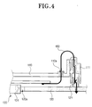
- Figure 4 is an enlarged schematic cross-section view showing a main part of Figure 3; and
- Figure 5 is a schematic perspective view showing the main part of Figure 3.
- Referring to Figures 3 to 5, an embodiment of a
tape recorder 100 having a capstan motor connection structure according to the present invention includes afirst connector 121 electrically connected to amain PCB 120, asecond connector 111 disposed adjacent to one side of amain base 110 for being electrically connected to thefirst connector 121, a through hole (or supporting hole) 110a formed in themain base 110 and acable 150, for electrically connecting asub PCB 140 of thecapstan motor 130 to thesecond connector 111, which passes through the throughhole 110a such that it is supported by the main PCB 120. Also, the main PCB 120 has ahole 120a formed therein. Thecapstan motor 130 is "built-in" with respect to themain PCB 120 with itsbody 131 being placed in thehole 120a such that a distance 'X' between themain base 110 and themain PCB 120 is reduced. Thetape recorder 100 is also provided with anouter case 101, atape cassette 2 and ahead drum 3. - Using the above-described structure, it is possible to reduce the distance 'X' between the
main base 110 and themain PCB 120 and a distance 'Y' between themain PCB 120 and thesub PCB 140. - Since this embodiment of the present invention solves the problem of the space restriction that is caused by the direct connection of the
connector 41 and theconnector holder 21 in the conventional tape recorder and the requirement for the space for the body of thecapstan motor 30 having the predetermined thickness, the overall height of the tape recorder can be reduced. - In other words, the above-described embodiment of the capstan motor connection structure according to the present invention has the
hole 120a formed in themain PCB 120 for allowing thecapstan motor 130 to be built into themain PCB 120, with itsbody 131 being placed in thehole 120a. Accordingly, themain PCB 120 is disposed nearer to a bottom of themain base 110 such that the distance 'X' between themain base 110 and themain PCB 120 is reduced. - In order to electrically connect the
sub PCB 140 of thecapstan motor 130 to themain PCB 120, one end of thecable 150 is connected to a circuit pattern of thesub PCB 140 by soldering, and the other end is passed through the throughhole 110a formed in themain base 110 and is then connected to thesecond connector 111 disposed at the end of themain base 110. Thecable 150 could be a ribbon-type cable such as a flexible printed circuit (FPC). Also, thesecond connector 111 is connected to thefirst connector 121 disposed on themain PCB 120, so that the space restriction caused by the change of connection position of the connector and the connector holder in the conventional tape recorder can be solved. Accordingly, the distance 'Y' between themain PCB 120 and thesub PCB 140 can be reduced. - Additionally, the
outer case 101 of thetape recorder 100 has arecess 101 a formed in the bottom thereof. Therecess 101 receives a head of thecapstan motor 130, thereby reducing the overall height of the tape recorder. - In the case of the above-described embodiment of the capstan motor connection structure according to the present invention, the distance 'X' between the
main base 110 and themain PCB 120 is actually or about 10 ± 1mm . Also, the distance 'Y' between themain PCB 120 and thesub PCB 140 is actually or about 7.5 ± 0.5mm. - In the case of employing the above-described embodiment of the capstan motor connection structure according to the present invention, the distance 'X' between the
main base 110 and themain PCB 120 is reduced by as much as or about 7.3 ± 1mm compared to the conventional capstan motor connection structure. - Also, the distance 'Y' between the
main PCB 120 and thesub PCB 140 is reduced by as much as or about 7.2 ± 0.5mm compared to the conventional capstan motor connection structure, thus the entire height of the tape recorder is lowered and slimmed. - In the case of the above-described embodiment of the capstan motor connection structure according to the present invention, since the distance 'X' between the
main base 110 and themain PCB 120 and the distance 'Y' between thesub PCB 140 and themain PCB 120 are reduced, the overall height of the tape recorder can be reduced.
Claims (19)
- An image recording and/or reproducing device, comprising:a main base having a hole therein; anda cable which passes through the hole and is connected to a sub printed circuit board (PCB) of a capstan motor by solder.
- An image recording and/or reproducing device as claimed in claim 1, further comprising:a first connector electrically connected to a main printed circuit board (PCB); anda second connector enclosing a potion of the cable, the second connector being disposed at one end of the main base and adapted to engage the first connector.
- An image recording and/or reproducing device, comprising:an outer case having a protruding portion forming a recess in the outer case which is adapted to receive a portion of a capstan motor of the VCR.
- A capstan motor unit for use in a video tape recorder, the capstan motor unit comprising:a sub printed circuit board (PCB) of a capstan motor; anda cable, connected to the sub PCB by soldering.
- A capstan motor connection structure of a tape recorder for electrically connecting a main printed circuit board (PCB) disposed in a substantially parallel relation to a main base of a deck of the tape recorder to a sub PCB of a capstan motor disposed on the main base, the capstan motor connection structure comprising:a first connector disposed at the main PCB to be electrically connected thereto;a second connector disposed at an end of the main base to be connected to the first connector; anda cable, penetratingly supported in a hole of the main base, the cable being electrically connected to the sub PCB of the capstan motor, and having a first portion thereof engaged within the second connector.
- A capstan motor connection structure as claimed in claim 5, wherein the cable is arranged to pass through the hole formed in the main base.
- A capstan motor connection structure as claimed in claim 5, wherein a second portion of the cable is electrically connected to a circuit pattern of the sub PCB by soldering.
- A capstan motor connection structure as claimed in claim 5, wherein the first and the second connectors are disposed proximate to a side edge of the main base to be connected to each other.
- A tape recorder comprising:a capstan motor having a sub printed circuit board (PCB) electrically connected to a main PCB disposed in a substantially parallel relation to a main base of a deck, the main base having a hole formed therein, the capstan motor being positioned such that its body is placed in a hole formed in the main PCB to reduce a distance between the main base and the main PCB; anda connection structure of the capstan motor, adapted to connect the sub PCB to the main PCB, the connection structure comprising:a first connector disposed at the main PCB to be electrically connected thereto;a second connector disposed at an end of the main base to be connected to the first connector; anda cable penetratingly supported in the hole of the main base, the cable being electrically connected to the sub PCB of the capstan motor, and having a first portion thereof engaged within the second connector.
- A tape recorder as claimed in claim 9, wherein a second portion of the cable is electrically connected to a circuit pattern of the sub PCB by soldering.
- A tape recorder as claimed in claim 9, wherein the first and the second connectors are disposed proximate to a side edge of the main base to be connected to each other.
- A tape recorder as claimed in claim 9, wherein a distance between the main base and the main PCB is about 10±1mm, and a distance between the main PCB and the sub PCB is about 7.5±0.5mm.
- A tape recording/reproducing apparatus comprising first and second circuit boards (140, 120), and a capstan motor (130) mounted such that its spindle projects through the first circuit board (140) away from the second circuit board (120) and having a body (131) substantially on one side of the first circuit board (140), characterised in that the distance between the first and second circuit boards (140, 120) is less than the length of the motor's body (131) located on said one side of the first circuit board (140).
- An apparatus according to claim 13, wherein the first and second circuit boards (140, 120) are substantially plane parallel.
- An apparatus according to claim 13 or 14, comprising first and second connectors (121, 111) for releasably electrically connecting the first circuit board (140) to the second circuit board (120), wherein the first and second connectors (121, 111) are not disposed between the first and second circuit boards (140, 120).
- An apparatus according to claim 15, wherein the second connector (111) is attached to the first end of a cable (150) and the second end of the cable (150) is attached to the first circuit board (140).
- An apparatus according to claim 13, 14, 15 or 16, wherein the motor's body (131) extends beyond the second circuit board (120).
- An apparatus according to claim 17, wherein the second circuit board (120) comprises a hole (120a) for receiving the motor's body (131).
- An apparatus according to claim 17 or 18, comprising an outer case (101), wherein the outer case (101) is bulged such that it receives a portion of the motor's body (131).
Applications Claiming Priority (2)
| Application Number | Priority Date | Filing Date | Title |
|---|---|---|---|
| KR10-2002-0058560A KR100451555B1 (en) | 2002-09-26 | 2002-09-26 | Connection structure of capstan motor for tape recorder |
| KR2002058560 | 2002-09-26 |
Publications (2)
| Publication Number | Publication Date |
|---|---|
| EP1403862A2 true EP1403862A2 (en) | 2004-03-31 |
| EP1403862A3 EP1403862A3 (en) | 2006-08-02 |
Family
ID=31973688
Family Applications (1)
| Application Number | Title | Priority Date | Filing Date |
|---|---|---|---|
| EP03255818A Withdrawn EP1403862A3 (en) | 2002-09-26 | 2003-09-17 | Tape recording/reproducing apparatus |
Country Status (4)
| Country | Link |
|---|---|
| US (1) | US7345843B2 (en) |
| EP (1) | EP1403862A3 (en) |
| KR (1) | KR100451555B1 (en) |
| CN (1) | CN1265387C (en) |
Cited By (1)
| Publication number | Priority date | Publication date | Assignee | Title |
|---|---|---|---|---|
| EP1679703A1 (en) * | 2004-12-31 | 2006-07-12 | Samsung Electronics Co., Ltd. | Video cassette recorder |
Families Citing this family (12)
| Publication number | Priority date | Publication date | Assignee | Title |
|---|---|---|---|---|
| GB0513375D0 (en) | 2005-06-30 | 2005-08-03 | Retento Ltd | Computer security |
| US9280365B2 (en) * | 2009-12-17 | 2016-03-08 | Honeywell International Inc. | Systems and methods for managing configuration data at disconnected remote devices |
| US10210162B1 (en) | 2010-03-29 | 2019-02-19 | Carbonite, Inc. | Log file management |
| US9715325B1 (en) | 2012-06-21 | 2017-07-25 | Open Text Corporation | Activity stream based interaction |
| US10686759B2 (en) | 2014-06-22 | 2020-06-16 | Webroot, Inc. | Network threat prediction and blocking |
| US10395133B1 (en) | 2015-05-08 | 2019-08-27 | Open Text Corporation | Image box filtering for optical character recognition |
| US10599844B2 (en) | 2015-05-12 | 2020-03-24 | Webroot, Inc. | Automatic threat detection of executable files based on static data analysis |
| US10289686B1 (en) | 2015-06-30 | 2019-05-14 | Open Text Corporation | Method and system for using dynamic content types |
| US10728034B2 (en) | 2018-02-23 | 2020-07-28 | Webroot Inc. | Security privilege escalation exploit detection and mitigation |
| US11159553B2 (en) | 2018-04-13 | 2021-10-26 | Webroot Inc. | Determining exploit prevention using machine learning |
| US11314863B2 (en) | 2019-03-27 | 2022-04-26 | Webroot, Inc. | Behavioral threat detection definition and compilation |
| US11170823B1 (en) | 2020-06-09 | 2021-11-09 | Western Digital Technologies, Inc. | Tape embedded drive with multiple feedthrough connections |
Family Cites Families (10)
| Publication number | Priority date | Publication date | Assignee | Title |
|---|---|---|---|---|
| JPH07122981B2 (en) | 1985-09-03 | 1995-12-25 | ソニー株式会社 | Cassette tape recorder |
| US5010432A (en) * | 1988-06-28 | 1991-04-23 | Sony Corporation | Rotary head drum apparatus comprising resilient electrical connectors |
| JP2775838B2 (en) | 1989-04-21 | 1998-07-16 | ソニー株式会社 | Portable VTR |
| US5566036A (en) | 1994-04-13 | 1996-10-15 | Lg Electronics Inc. | Cable connecting apparatus between audio control head and main printed circuit board for video cassette tape recorder |
| KR0129547Y1 (en) * | 1995-08-21 | 1998-12-15 | 배순훈 | Fixing structure of capstan motor for tape recorder |
| JP3035495B2 (en) | 1996-07-08 | 2000-04-24 | 三洋電機株式会社 | Rotary table drive and metal core printed circuit board |
| KR100237036B1 (en) * | 1996-12-30 | 2000-01-15 | 전주범 | Assembly structure of capstan motor for tape recorder |
| KR19990003033U (en) * | 1997-06-30 | 1999-01-25 | 배순훈 | Capstan motor assembly structure of video cassette tape recorder |
| KR20000003059A (en) | 1998-06-25 | 2000-01-15 | 윤종용 | Head drum assembly of tape recorder |
| CN1392552A (en) * | 2001-06-15 | 2003-01-22 | 株式会社三协精机制作所 | Magnetic type travel device and motor base board and main guide shaft motor |
-
2002
- 2002-09-26 KR KR10-2002-0058560A patent/KR100451555B1/en not_active Expired - Fee Related
-
2003
- 2003-08-07 US US10/635,655 patent/US7345843B2/en not_active Expired - Fee Related
- 2003-09-17 EP EP03255818A patent/EP1403862A3/en not_active Withdrawn
- 2003-09-19 CN CNB031585795A patent/CN1265387C/en not_active Expired - Fee Related
Cited By (1)
| Publication number | Priority date | Publication date | Assignee | Title |
|---|---|---|---|---|
| EP1679703A1 (en) * | 2004-12-31 | 2006-07-12 | Samsung Electronics Co., Ltd. | Video cassette recorder |
Also Published As
| Publication number | Publication date |
|---|---|
| KR20040026925A (en) | 2004-04-01 |
| EP1403862A3 (en) | 2006-08-02 |
| US7345843B2 (en) | 2008-03-18 |
| CN1497597A (en) | 2004-05-19 |
| CN1265387C (en) | 2006-07-19 |
| KR100451555B1 (en) | 2004-10-08 |
| US20040062521A1 (en) | 2004-04-01 |
Similar Documents
| Publication | Publication Date | Title |
|---|---|---|
| EP1403862A2 (en) | Tape recording/reproducing apparatus | |
| US5502604A (en) | Disk drive with rail mounting arrangement | |
| US5245486A (en) | Disk unit with a side mounted board | |
| JP2872892B2 (en) | FPC for magnetic tape device and magnetic tape device | |
| US5644474A (en) | Video cassette recorder incorporating therein a grounding system | |
| US20050097583A1 (en) | Complex electronic device having circuit board for operation button control and device units connected by bent or folded flexible flat cables | |
| EP1607962B1 (en) | A tape cassette deck | |
| KR100243794B1 (en) | Recording and / or playback apparatus with reel and reel covers | |
| US5692696A (en) | Recording and/or reproducing apparatus having reel mounts and reels mount cover | |
| CN1062671C (en) | Full erase head assembler for video cassette recorder | |
| JPH05165049A (en) | Liquid crystal display device | |
| US6028747A (en) | Head drum assembly having a member locating and fixing video heads on an upper drum | |
| KR20000001778U (en) | Connection device of head drum assembly | |
| JPH05236306A (en) | Video camera | |
| JP2000188487A (en) | Fpc cable structure and magnetic disk device using the same | |
| JP3127935B2 (en) | Video tape recorder | |
| JP3020345U (en) | Electronics | |
| US5313348A (en) | Magnetic recording/reproducing apparatus | |
| KR200366402Y1 (en) | Magnetic recording/reproducing apparatus | |
| KR200283730Y1 (en) | Head drum connection structure | |
| JPS59161502U (en) | wiring device | |
| JP3175488B2 (en) | Rotating head cylinder device | |
| JPH05266451A (en) | Magnetic head device | |
| JP2001148188A (en) | Magnetic disk device | |
| KR19990005463U (en) | VRC's Drum Circuit Board Connection Structure |
Legal Events
| Date | Code | Title | Description |
|---|---|---|---|
| PUAI | Public reference made under article 153(3) epc to a published international application that has entered the european phase |
Free format text: ORIGINAL CODE: 0009012 |
|
| AK | Designated contracting states |
Kind code of ref document: A2 Designated state(s): AT BE BG CH CY CZ DE DK EE ES FI FR GB GR HU IE IT LI LU MC NL PT RO SE SI SK TR |
|
| AX | Request for extension of the european patent |
Extension state: AL LT LV MK |
|
| RAP1 | Party data changed (applicant data changed or rights of an application transferred) |
Owner name: SAMSUNG ELECTRONICS CO., LTD. |
|
| PUAL | Search report despatched |
Free format text: ORIGINAL CODE: 0009013 |
|
| AK | Designated contracting states |
Kind code of ref document: A3 Designated state(s): AT BE BG CH CY CZ DE DK EE ES FI FR GB GR HU IE IT LI LU MC NL PT RO SE SI SK TR |
|
| AX | Request for extension of the european patent |
Extension state: AL LT LV MK |
|
| 17P | Request for examination filed |
Effective date: 20060905 |
|
| AKX | Designation fees paid |
Designated state(s): DE GB NL |
|
| 17Q | First examination report despatched |
Effective date: 20080221 |
|
| STAA | Information on the status of an ep patent application or granted ep patent |
Free format text: STATUS: THE APPLICATION IS DEEMED TO BE WITHDRAWN |
|
| 18D | Application deemed to be withdrawn |
Effective date: 20090630 |