EP1403606A2 - Heat exchanger module - Google Patents
Heat exchanger module Download PDFInfo
- Publication number
- EP1403606A2 EP1403606A2 EP20030021616 EP03021616A EP1403606A2 EP 1403606 A2 EP1403606 A2 EP 1403606A2 EP 20030021616 EP20030021616 EP 20030021616 EP 03021616 A EP03021616 A EP 03021616A EP 1403606 A2 EP1403606 A2 EP 1403606A2
- Authority
- EP
- European Patent Office
- Prior art keywords
- mounting
- brackets
- heat exchanger
- heat exchangers
- condenser
- Prior art date
- Legal status (The legal status is an assumption and is not a legal conclusion. Google has not performed a legal analysis and makes no representation as to the accuracy of the status listed.)
- Withdrawn
Links
Images







Classifications
-
- F—MECHANICAL ENGINEERING; LIGHTING; HEATING; WEAPONS; BLASTING
- F28—HEAT EXCHANGE IN GENERAL
- F28F—DETAILS OF HEAT-EXCHANGE AND HEAT-TRANSFER APPARATUS, OF GENERAL APPLICATION
- F28F21/00—Constructions of heat-exchange apparatus characterised by the selection of particular materials
- F28F21/06—Constructions of heat-exchange apparatus characterised by the selection of particular materials of plastics material
- F28F21/067—Details
-
- F—MECHANICAL ENGINEERING; LIGHTING; HEATING; WEAPONS; BLASTING
- F28—HEAT EXCHANGE IN GENERAL
- F28D—HEAT-EXCHANGE APPARATUS, NOT PROVIDED FOR IN ANOTHER SUBCLASS, IN WHICH THE HEAT-EXCHANGE MEDIA DO NOT COME INTO DIRECT CONTACT
- F28D1/00—Heat-exchange apparatus having stationary conduit assemblies for one heat-exchange medium only, the media being in contact with different sides of the conduit wall, in which the other heat-exchange medium is a large body of fluid, e.g. domestic or motor car radiators
- F28D1/02—Heat-exchange apparatus having stationary conduit assemblies for one heat-exchange medium only, the media being in contact with different sides of the conduit wall, in which the other heat-exchange medium is a large body of fluid, e.g. domestic or motor car radiators with heat-exchange conduits immersed in the body of fluid
- F28D1/04—Heat-exchange apparatus having stationary conduit assemblies for one heat-exchange medium only, the media being in contact with different sides of the conduit wall, in which the other heat-exchange medium is a large body of fluid, e.g. domestic or motor car radiators with heat-exchange conduits immersed in the body of fluid with tubular conduits
- F28D1/0408—Multi-circuit heat exchangers, e.g. integrating different heat exchange sections in the same unit or heat exchangers for more than two fluids
- F28D1/0426—Multi-circuit heat exchangers, e.g. integrating different heat exchange sections in the same unit or heat exchangers for more than two fluids with units having particular arrangement relative to the large body of fluid, e.g. with interleaved units or with adjacent heat exchange units in common air flow or with units extending at an angle to each other or with units arranged around a central element
- F28D1/0435—Combination of units extending one behind the other
-
- F—MECHANICAL ENGINEERING; LIGHTING; HEATING; WEAPONS; BLASTING
- F28—HEAT EXCHANGE IN GENERAL
- F28F—DETAILS OF HEAT-EXCHANGE AND HEAT-TRANSFER APPARATUS, OF GENERAL APPLICATION
- F28F9/00—Casings; Header boxes; Auxiliary supports for elements; Auxiliary members within casings
- F28F9/001—Casings in the form of plate-like arrangements; Frames enclosing a heat exchange core
- F28F9/002—Casings in the form of plate-like arrangements; Frames enclosing a heat exchange core with fastening means for other structures
-
- F—MECHANICAL ENGINEERING; LIGHTING; HEATING; WEAPONS; BLASTING
- F28—HEAT EXCHANGE IN GENERAL
- F28D—HEAT-EXCHANGE APPARATUS, NOT PROVIDED FOR IN ANOTHER SUBCLASS, IN WHICH THE HEAT-EXCHANGE MEDIA DO NOT COME INTO DIRECT CONTACT
- F28D1/00—Heat-exchange apparatus having stationary conduit assemblies for one heat-exchange medium only, the media being in contact with different sides of the conduit wall, in which the other heat-exchange medium is a large body of fluid, e.g. domestic or motor car radiators
- F28D1/02—Heat-exchange apparatus having stationary conduit assemblies for one heat-exchange medium only, the media being in contact with different sides of the conduit wall, in which the other heat-exchange medium is a large body of fluid, e.g. domestic or motor car radiators with heat-exchange conduits immersed in the body of fluid
- F28D1/04—Heat-exchange apparatus having stationary conduit assemblies for one heat-exchange medium only, the media being in contact with different sides of the conduit wall, in which the other heat-exchange medium is a large body of fluid, e.g. domestic or motor car radiators with heat-exchange conduits immersed in the body of fluid with tubular conduits
- F28D1/053—Heat-exchange apparatus having stationary conduit assemblies for one heat-exchange medium only, the media being in contact with different sides of the conduit wall, in which the other heat-exchange medium is a large body of fluid, e.g. domestic or motor car radiators with heat-exchange conduits immersed in the body of fluid with tubular conduits the conduits being straight
- F28D1/0535—Heat-exchange apparatus having stationary conduit assemblies for one heat-exchange medium only, the media being in contact with different sides of the conduit wall, in which the other heat-exchange medium is a large body of fluid, e.g. domestic or motor car radiators with heat-exchange conduits immersed in the body of fluid with tubular conduits the conduits being straight the conduits having a non-circular cross-section
- F28D1/05366—Assemblies of conduits connected to common headers, e.g. core type radiators
Definitions
- the present invention relates to a heat exchanger module, in which at least a first heat exchanger and a second heat exchanger are integrated with each other through brackets, and can be effectively applied to a cooling module in which a radiator for a vehicle and an external heat exchanger of an air conditioner for a vehicle are integrated.
- a radiator and a condenser are integrated by inserts (side plates) or fins, etc., and mounting brackets for mounting the same to a vehicle are secured to header tank portions (see Japanese Unexamined Patent Publication No. 11-142084, for example).
- the radiator and the condenser Before making the radiator and the condenser integral with each other, the radiator and the condenser must be manufactured separately, because the specifications thereof are quite different.
- the present invention is aimed at provision of a structure applicable to a heat exchanger module in which at least two heat exchangers are integrated with each other after they are manufactured separately.
- a heat exchanger module comprises a first heat exchange 1 and a second heat exchanger 2 which are integrated with each other through brackets 3, the first and second heat exchangers 1 and 2 each being constituted by solder-brazing a plurality of tubes and header tanks connected thereto, which are located at opposite ends of the plurality of tubes in the longitudinal direction, wherein the first and second heat exchangers 1 and 2 are arranged with core surfaces thereof being opposed to each other, the brackets 3 are provided with mounting parts 3b for mounting the heat exchangers 1 and 2 to a vehicle, and the brackets 3 are made of resin and located between the heat exchangers 1 and 2.
- the brackets 3 made of resin having lower thermal conductivity than a metal are located between the heat exchangers 1 and 2, so that heat transfer, from the heat exchanger on a higher temperature side to the heat exchanger on a lower temperature side, can be restricted.
- a predetermined space must be provided between cores of the heat exchanger 1 and 2.
- the heat exchangers 1 and 2 are assembled with and secured to the brackets 3 so that, for example, the position of the second heat exchanger 2 with respect to the first heat exchanger 1 can be easily determined. Therefore, the assembling of the heat exchanger module can be facilitated and heat exchange between the first and second heat exchangers 1 and 2 can be restricted, due to a predetermined space provided between the cores of the heat exchangers 1 and 2.
- the bracket 3 has mounting parts 3b and bracket body 3a in the form of a strip plate which is located between a header tank 1d of the first heat exchanger 1 and a header tank 2d of the second heat exchanger 2.
- the mounting part 3b is provided, on a mounting stay 3c projecting from an end side of the bracket body 3a in the longitudinal direction, in a direction substantially orthogonal to the longitudinal direction of the bracket body 3a.
- the mounting stay 3c is provided on its root side with a reinforcing part 3d to resist a moment acting on the mounting stay 3c.
- the mounting stay 3c projects from the bracket body 3a toward the core sides of the heat exchangers 1 and 2 and the reinforcing part 3d has through holes 3e extending in a direction orthogonal to the core surface.
- the reinforcing parts 3d which would otherwise obstruct the cooling air flowing through the core, can enhance the rigidity of the brackets 3 without reducing the cooling efficiency of the heat exchanger module.
- the brackets 3 are located on opposite end sides of the heat exchangers 1 and 2, and at least one of the brackets 3 are secured to the heat exchangers 1 and 2 by pin-shaped securing means 4 extending in a direction orthogonal to the core surface.
- a fan mounting part 3f for mounting a fan, to feed air to the heat exchangers 1 and 2, is provided in the vicinity of the mounting part 3b.
- a heat exchanger module of the present invention is applied to a cooling module in which a radiator for a vehicle, and an external heat exchanger of an air conditioner for a vehicle, are integrated.
- Fig. 1 is a perspective view of a cooling module of Embodiment 1 viewed from a downstream side of an air flow.
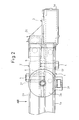
- Fig. 2 is a top view of A-part in Fig. 1.
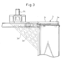
- Fig. 3 is a front view of A-part in Fig. 1.
- Fig. 4 is a front view of a bracket 3.
- a radiator 1 cools cooling water due to a heat-exchange between the cooling water circulating in an engine and the air.
- a condenser 2 (see Fig. 2) cools and condenses high-pressure refrigerant discharged from a compressor.
- the radiator 1 and the condenser 2 are substantially identical in structure.
- the radiator 1 and the condenser 2 are each comprised of a core 1c having a plurality of tubes 1a through which fluid, i.e., cooling water in the radiator 1 or refrigerant in the condenser 2, and having fins 1b welded to external surfaces of the tubes 1a to increase a heat transfer surface area in contact with the air, having header tanks 1d which are connected to the plurality of tubes 1a at opposite ends of the plurality of tubes 1a in the longitudinal direction and which extend in a direction substantially orthogonal to the longitudinal direction of the tubes 1a, and having inserts 1e which are located at opposite ends of the core 1c and which extend parallel to the longitudinal direction of the tubes 1a to reinforce the core 1c, etc.
- all of the above components being made of aluminum alloy, are integrated by solder-brazing.
- the condenser 2 is not shown in Fig. 1 and, hence, numerals are assigned to the tubes, the fins, the core, the header tanks and the inserts of the radiator 1, only.
- solder-brazing refers to bonding by means of braze or solder, without fusing a base material.
- the bonding using a filler metal, called a brazing material, whose fusing point is not less than 450°C is referred to as brazing.
- the bonding by the use of a filler, called solder, whose fusing point is not more than 450°C is referred to as soldering.
- the radiator 1 and the condenser 2 are arranged with core surfaces thereof being opposed to each other with a determined space.
- the radiator 1 and the condenser 2 are secured to brackets 3 located therebetween, are integrated with each other, and are mounted to a vehicle body through the brackets 3.
- the bracket 3 has the bracket body 3a in the form of a strip plate extending in the upward and downward direction at the portion between the header tank 1d of the radiator 1 and the header tank 2d (see Fig. 2), that is, the portion corresponding to the ends of the radiator 1 and the condenser 2, the mounting parts 3b for mounting the radiator 1 and the condenser 2, i.e., the cooling module, which are integrated through the brackets 3, to a vehicle body, and the mounting stays 3c, etc., in the form of strip plates projecting from end sides of the bracket body 3a in the longitudinal direction, in a direction substantially orthogonal to the longitudinal direction of the bracket body 3a, i.e., toward core sides of the radiator 1 and the condenser 2, according to the present embodiment.
- the mounting parts 3b are provided on front end sides of the mounting stays 3c.
- the mounting stays 3c are provided on their root sides with generally triangular plate shaped reinforcing parts 3d which serve as reinforcing members to resist a moment acting on the mounting stays 3c.
- the reinforcing parts 3d have a plurality of through holes 3e extending in a direction orthogonal to the core surfaces, i.e., in a direction of an air flow.
- the reinforcing part 3d has a truss structure, by making the shapes of the holes 3e substantially triangular, so that no substantial reduction of the strength occurs.
- the bracket body 3a extends from parts corresponding to the header tanks 1d and 2d toward sides of the cores 1c and 2c, as shown in Fig. 5.
- the bracket bodies 3a, the mounting parts 3b, the mounting stays 3c and the reinforcing parts 3d are integrally molded by means of resin (e.g., glass-fiber-imbedded nylon).
- At least one of the right and left brackets 3 of the cooling module (both the brackets in the present embodiment) is secured, on its upper end side, to the radiator 1 and the condenser 2 through bolts 4 which serve as a pin-shaped securing means extending in a direction orthogonal to the core surfaces, as shown in Fig. 2.
- the inserts 1e and 2e are each comprised of a bottom surface and two opposite side walls raised from the bottom surface and are in the form of a channel generally of a U-shape in cross section.
- the lower ends of the radiator 1 and the condenser 2 are secured to the brackets 3 by fitting the projections 3g provided on the lower end sides of the brackets 3, in the substantially U-shaped recesses of the inserts 1e and 2e.
- the projections 3g are provided with tapered parts 3m obliquely oriented to the bracket body 3a side.
- nuts 5 are embedded in the reinforcing parts 3d and are integrated with the brackets 3 when the brackets 3 are manufactured, so that the bolts 4 are inserted and fastened in the nuts 5 through bolt holes 1f and 2f provided in the inserts 1e and 2e.
- the fan mounting parts 3f for mounting a fan shroud are provided integrally to the brackets 3 in the vicinity of the mounting parts 3b.
- the fan shroud covers the stays for mounting the fan to blow cooling air to the cooling module, the cooling module and the fan, in order to prevent an airflow induced by the fan from detouring around the cooling module.
- the brackets 3 are made of resin and are located between the radiator 1 and the condenser 2 so that heat exchange between the radiator 1 and the condenser 2 can be restricted.
- the brackets 3 made of resin, whose thermal conductivity is lower than that of a metal, are provided between the radiator 1 and the condenser 2, so that heat transfer from the radiator to the condenser 2 can be restricted and reduction of the cooling efficiency of the condenser 2 can be prevented.
- a predetermined space must be provided between the core 1c of the radiator 1 and the core 2c of the condenser 2.
- the radiator 1 and the condenser 2 are assembled with and secured to the brackets 3 so that the position of the condenser 2 with respect to the radiator 1 can be easily determined. Therefore, the assembling of the cooling module can be facilitated and heat exchange between the radiator 1 and the condenser 2 can be restricted, due to a predetermined space provided between the core 1c of the radiator 1 and the core 2c of the condenser 2.
- the mounting parts 3b for mounting the cooling module to a vehicle are provided in the brackets 3 and, thus, a dimensional difference between the upper mounting parts 3b and the lower mounting parts 3b is within a manufacturing tolerance (manufacturing irregularity) of the brackets 3.
- the mounting parts 3b were provided in the radiator 1 or the condenser 2, a dimensional difference between the upper mounting parts 3b and the lower mounting parts 3b would be within a manufacturing tolerance (allowable manufacturing irregularity) of the radiator 1 or the condenser 2. Nevertheless, if the mounting parts 3b are provided in the brackets 3, the dimensional difference between the upper and lower mounting parts 3b becomes smaller, because the brackets 3 are resin-molded products and the radiator 1 and the condenser 2 are brazed products.
- the dimensional difference between the upper mounting parts 3b and the lower mounting parts 3b can be made smaller so that the mounting operation of the cooling module to a vehicle can be facilitated.
- the reinforcing parts 3d have through-holes 3e extending in a direction orthogonal to the core surfaces of the core 1c and the core 2c. As the holes 3e permit the cooling air to pass therethrough, the reinforcing parts 3d, which would otherwise obstruct the cooling air flowing through the cores 1c and 2c, can enhance the rigidity of the brackets 3 without reducing the cooling efficiency of the cooling module.
- the radiator 1 and the condenser 2 are integrated through the brackets 3 and the brackets 3 are provided on opposite end sides of the both heat exchangers. If the radiator 1 is different in size from the condenser 2, both the radiator 1 and the condenser 2 may not be mounted to the brackets 3.
- the radiator 1 and the condenser 2 are secured to the brackets 3 through the bolts 4 extending in a direction orthogonal to the core surfaces. If holes in which the bolts 4 are inserted are larger than the diameters of the bolts 4 or are elongated holes, a dimensional difference between the radiator 1 and the condenser 2 can be easily absorbed, so that the radiator 1 and the condenser 2 can be easily mounted to the brackets 3.
- the heat exchangers 1 and 2 are free from the weight of the fan and the fan shroud.
- bracket bodies 3a extend from portions corresponding to the header tanks 1d and 2d to the cores 1c and 2c, it is possible to provide the bracket bodies 3a with reinforcing flanges 3k, so that the bracket bodies 3a generally exhibit a T-shape in cross section as shown in Fig. 5. Consequently, the flexural rigidity and the buckling strength of the bracket bodies 3a can be increased.
- the flanges 3k can be arranged on the cores 1c and 2c sides.
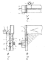
- the radiator 1 and the condenser 2 are secured to the brackets 3 through the bolts 4 extending in a direction orthogonal to the core surfaces in Embodiment 1, according to the present embodiment, as shown in Figs. 7A-7C, the condenser 2 is secured to the brackets 3 through the bolts 4' extending parallel to the core surfaces.
- the bracket bodies 3a are provided with stays 3j for fastening the condenser 2.
- the mounting stays 1f provided on the radiator 1 are united to the stays 3j, and both the radiator 1 and the condenser 2 are secured by fastening the bolts 4'.
- the radiator 1 and the condenser 2 are secured to the brackets 3 through the bolts 4' extending parallel to the core surfaces.
- the fan mounting parts 3f are provided on corresponding portions of the brackets 3 at the ends of the header tanks 1d and 2d in the longitudinal direction.
- the mounting parts 3b are provided on the brackets 3 at their parts corresponding to the ends in the longitudinal direction of the header tanks 1d and 2d.
- the heat exchangers 1 and 2 are secured to the brackets 3 through the bolts in the above embodiments, according to the present embodiment, as shown in Fig. 12, the heat exchanger (the condenser 2 in Fig. 12) is secured to the brackets 3 through snap-fits 3h.
- the snap-fits constitute a means for detachably securing two members, due to an elastic deformation of projections in the form of hook-shaped pins.
- bracket bodies 3a are provided between the header tanks 1d and 2d but the present invention is not limited thereto.
- the heat exchanger modules are comprised of the radiator and the condenser, but the present invention is not limited thereto and may be applied to a module comprised of other heat exchangers.
Landscapes
- Engineering & Computer Science (AREA)
- Physics & Mathematics (AREA)
- Thermal Sciences (AREA)
- Mechanical Engineering (AREA)
- General Engineering & Computer Science (AREA)
- Details Of Heat-Exchange And Heat-Transfer (AREA)
- Cooling, Air Intake And Gas Exhaust, And Fuel Tank Arrangements In Propulsion Units (AREA)
- Heat-Exchange Devices With Radiators And Conduit Assemblies (AREA)
- Transformer Cooling (AREA)
- Air-Conditioning For Vehicles (AREA)
Abstract
Description
- The present invention relates to a heat exchanger module, in which at least a first heat exchanger and a second heat exchanger are integrated with each other through brackets, and can be effectively applied to a cooling module in which a radiator for a vehicle and an external heat exchanger of an air conditioner for a vehicle are integrated.
- Conventionally, a radiator and a condenser are integrated by inserts (side plates) or fins, etc., and mounting brackets for mounting the same to a vehicle are secured to header tank portions (see Japanese Unexamined Patent Publication No. 11-142084, for example).
- Before making the radiator and the condenser integral with each other, the radiator and the condenser must be manufactured separately, because the specifications thereof are quite different.
- In this regard, according to a prior art disclosed in Japanese Unexamined Patent Publication No. 11-142084, a cooling module in which a radiator has already been integrated with a condenser is mounted in a vehicle through brackets. Thus, it is difficult to apply the prior art to the cooling module in which both of the heat exchangers, i.e., the radiator and the condenser, are integrated with each other after they are manufactured separately.
- In view of the above problem, the present invention is aimed at provision of a structure applicable to a heat exchanger module in which at least two heat exchangers are integrated with each other after they are manufactured separately.
- To achieve the above objective, according to the present invention, a heat exchanger module comprises a
first heat exchange 1 and asecond heat exchanger 2 which are integrated with each other throughbrackets 3, the first andsecond heat exchangers second heat exchangers brackets 3 are provided withmounting parts 3b for mounting theheat exchangers brackets 3 are made of resin and located between theheat exchangers - The
brackets 3 made of resin having lower thermal conductivity than a metal are located between theheat exchangers - A predetermined space must be provided between cores of the
heat exchanger heat exchangers brackets 3 so that, for example, the position of thesecond heat exchanger 2 with respect to thefirst heat exchanger 1 can be easily determined. Therefore, the assembling of the heat exchanger module can be facilitated and heat exchange between the first andsecond heat exchangers heat exchangers - According to the present invention, the
bracket 3 has mountingparts 3b andbracket body 3a in the form of a strip plate which is located between aheader tank 1d of thefirst heat exchanger 1 and aheader tank 2d of thesecond heat exchanger 2. - According to the present invention, the
mounting part 3b is provided, on a mounting stay 3c projecting from an end side of thebracket body 3a in the longitudinal direction, in a direction substantially orthogonal to the longitudinal direction of thebracket body 3a. Themounting stay 3c is provided on its root side with a reinforcingpart 3d to resist a moment acting on themounting stay 3c. - Further, according to the present invention, the mounting stay 3c projects from the
bracket body 3a toward the core sides of theheat exchangers part 3d has through holes 3e extending in a direction orthogonal to the core surface. - As the holes 3e permit the cooling air to pass therethrough, the reinforcing
parts 3d, which would otherwise obstruct the cooling air flowing through the core, can enhance the rigidity of thebrackets 3 without reducing the cooling efficiency of the heat exchanger module. - According to the present invention, the
brackets 3 are located on opposite end sides of theheat exchangers brackets 3 are secured to theheat exchangers - Due to this arrangement, if a hole in which the
securing means 4 is inserted is larger than the diameter of the securing means 4 or is an elongated hole, a dimensional difference between theheat exchangers brackets 3 can be easily mounted to theheat exchangers - Further, according to the present invention, a
fan mounting part 3f for mounting a fan, to feed air to theheat exchangers mounting part 3b. - The present invention may be more fully understood from the description of preferred embodiments of the invention, as set forth below, together with the accompanying drawings.
- In the drawings:
- Fig. 1 is a perspective view of a cooling module according to
Embodiment 1 of the present invention, viewed from the downstream side of an air flow. - Fig. 2 is a top view of a part "A" in Fig. 1.
- Fig. 3 is a front view of a part "A" in Fig. 1.
- Fig. 4 is a front view of a bracket according to
Embodiment 1 of the present invention. - Fig. 5 is a sectional view of a bracket, etc., according to Embodiment 1 of the present invention.
- Fig. 6 shows how to assemble a cooling module according to
Embodiment 1 of the present invention. - Figs. 7A, 7B and 7C are three different views of a significant component of a cooling module according to
Embodiment 2 of the present invention. - Figs. 8A, 8B and 8C are three different views of a significant component of a cooling module according to
Embodiment 3 of the present invention. - Figs. 9A, 9B and 9C are three different views of a significant component of a cooling module according to
Embodiment 4 of the present invention. - Figs. 10A, 10B and 10C are three different views of a significant component of a cooling module according to
Embodiment 5 of the present invention. - Fig. 11 is a front view of a bracket according to Embodiment 6 of the present invention.
- Fig. 12 is a perspective view of a cooling module, according to Embodiment 7 of the present invention, viewed from the upstream side of an air flow.
- According to the present embodiment, a heat exchanger module of the present invention is applied to a cooling module in which a radiator for a vehicle, and an external heat exchanger of an air conditioner for a vehicle, are integrated.
- Fig. 1 is a perspective view of a cooling module of
Embodiment 1 viewed from a downstream side of an air flow. Fig. 2 is a top view of A-part in Fig. 1. Fig. 3 is a front view of A-part in Fig. 1. Fig. 4 is a front view of abracket 3. - A
radiator 1 cools cooling water due to a heat-exchange between the cooling water circulating in an engine and the air. A condenser 2 (see Fig. 2) cools and condenses high-pressure refrigerant discharged from a compressor. - The
radiator 1 and thecondenser 2 are substantially identical in structure. In particular, as shown in Fig. 1, theradiator 1 and thecondenser 2 are each comprised of a core 1c having a plurality oftubes 1a through which fluid, i.e., cooling water in theradiator 1 or refrigerant in thecondenser 2, and having fins 1b welded to external surfaces of thetubes 1a to increase a heat transfer surface area in contact with the air, havingheader tanks 1d which are connected to the plurality oftubes 1a at opposite ends of the plurality oftubes 1a in the longitudinal direction and which extend in a direction substantially orthogonal to the longitudinal direction of thetubes 1a, and havinginserts 1e which are located at opposite ends of the core 1c and which extend parallel to the longitudinal direction of thetubes 1a to reinforce the core 1c, etc. According to the present embodiment, all of the above components, being made of aluminum alloy, are integrated by solder-brazing. - The
condenser 2 is not shown in Fig. 1 and, hence, numerals are assigned to the tubes, the fins, the core, the header tanks and the inserts of theradiator 1, only. - "Solder-brazing", as described in "Connection·Cementation Technology" (published by Tokyo Denki University Press), refers to bonding by means of braze or solder, without fusing a base material. The bonding using a filler metal, called a brazing material, whose fusing point is not less than 450°C is referred to as brazing. The bonding by the use of a filler, called solder, whose fusing point is not more than 450°C is referred to as soldering.
- As shown in Fig. 2, the
radiator 1 and thecondenser 2 are arranged with core surfaces thereof being opposed to each other with a determined space. Theradiator 1 and thecondenser 2 are secured tobrackets 3 located therebetween, are integrated with each other, and are mounted to a vehicle body through thebrackets 3. - As shown in Fig. 4, the
bracket 3 has thebracket body 3a in the form of a strip plate extending in the upward and downward direction at the portion between theheader tank 1d of theradiator 1 and theheader tank 2d (see Fig. 2), that is, the portion corresponding to the ends of theradiator 1 and thecondenser 2, themounting parts 3b for mounting theradiator 1 and thecondenser 2, i.e., the cooling module, which are integrated through thebrackets 3, to a vehicle body, and the mounting stays 3c, etc., in the form of strip plates projecting from end sides of thebracket body 3a in the longitudinal direction, in a direction substantially orthogonal to the longitudinal direction of thebracket body 3a, i.e., toward core sides of theradiator 1 and thecondenser 2, according to the present embodiment. The mountingparts 3b are provided on front end sides of the mounting stays 3c. - The mounting stays 3c are provided on their root sides with generally triangular plate shaped reinforcing
parts 3d which serve as reinforcing members to resist a moment acting on the mounting stays 3c. The reinforcingparts 3d have a plurality of through holes 3e extending in a direction orthogonal to the core surfaces, i.e., in a direction of an air flow. - According to the present embodiment, the reinforcing
part 3d has a truss structure, by making the shapes of the holes 3e substantially triangular, so that no substantial reduction of the strength occurs. - The
bracket body 3a extends from parts corresponding to theheader tanks - According to the present embodiment, the
bracket bodies 3a, the mountingparts 3b, the mounting stays 3c and the reinforcingparts 3d are integrally molded by means of resin (e.g., glass-fiber-imbedded nylon). - At least one of the right and
left brackets 3 of the cooling module (both the brackets in the present embodiment) is secured, on its upper end side, to theradiator 1 and thecondenser 2 throughbolts 4 which serve as a pin-shaped securing means extending in a direction orthogonal to the core surfaces, as shown in Fig. 2. - The
inserts - As shown in Fig. 6, the lower ends of the
radiator 1 and thecondenser 2 are secured to thebrackets 3 by fitting theprojections 3g provided on the lower end sides of thebrackets 3, in the substantially U-shaped recesses of theinserts projections 3g are provided withtapered parts 3m obliquely oriented to thebracket body 3a side. - According to the present embodiment, as shown in Fig. 2,
nuts 5 are embedded in the reinforcingparts 3d and are integrated with thebrackets 3 when thebrackets 3 are manufactured, so that thebolts 4 are inserted and fastened in thenuts 5 throughbolt holes inserts - The
fan mounting parts 3f for mounting a fan shroud are provided integrally to thebrackets 3 in the vicinity of the mountingparts 3b. The fan shroud covers the stays for mounting the fan to blow cooling air to the cooling module, the cooling module and the fan, in order to prevent an airflow induced by the fan from detouring around the cooling module. - Next, the operation and the effect of the embodiment will be explained.
- According to the present embodiment, the
brackets 3 are made of resin and are located between theradiator 1 and thecondenser 2 so that heat exchange between theradiator 1 and thecondenser 2 can be restricted. - That is, because the temperature of the cooling water circulating in the
radiator 1 is higher than that of the cooling medium circulating in thecondenser 2, if theradiator 1 and thecondenser 2 are integrated in close contact with each other, a heat transfer from theradiator 1 to thecondenser 2 occurs, thus leading to reduction of the cooling efficiency of thecondenser 2. However, according to the present embodiment, thebrackets 3 made of resin, whose thermal conductivity is lower than that of a metal, are provided between theradiator 1 and thecondenser 2, so that heat transfer from the radiator to thecondenser 2 can be restricted and reduction of the cooling efficiency of thecondenser 2 can be prevented. - A predetermined space must be provided between the core 1c of the
radiator 1 and the core 2c of thecondenser 2. According to the present embodiment, theradiator 1 and thecondenser 2 are assembled with and secured to thebrackets 3 so that the position of thecondenser 2 with respect to theradiator 1 can be easily determined. Therefore, the assembling of the cooling module can be facilitated and heat exchange between theradiator 1 and thecondenser 2 can be restricted, due to a predetermined space provided between the core 1c of theradiator 1 and the core 2c of thecondenser 2. - Further, the mounting
parts 3b for mounting the cooling module to a vehicle are provided in thebrackets 3 and, thus, a dimensional difference between the upper mountingparts 3b and thelower mounting parts 3b is within a manufacturing tolerance (manufacturing irregularity) of thebrackets 3. - If the mounting
parts 3b were provided in theradiator 1 or thecondenser 2, a dimensional difference between the upper mountingparts 3b and thelower mounting parts 3b would be within a manufacturing tolerance (allowable manufacturing irregularity) of theradiator 1 or thecondenser 2. Nevertheless, if the mountingparts 3b are provided in thebrackets 3, the dimensional difference between the upper and lower mountingparts 3b becomes smaller, because thebrackets 3 are resin-molded products and theradiator 1 and thecondenser 2 are brazed products. - Consequently, the dimensional difference between the upper mounting
parts 3b and thelower mounting parts 3b can be made smaller so that the mounting operation of the cooling module to a vehicle can be facilitated. - The reinforcing
parts 3d have through-holes 3e extending in a direction orthogonal to the core surfaces of the core 1c and the core 2c. As the holes 3e permit the cooling air to pass therethrough, the reinforcingparts 3d, which would otherwise obstruct the cooling air flowing through the cores 1c and 2c, can enhance the rigidity of thebrackets 3 without reducing the cooling efficiency of the cooling module. - According to the present embodiment, the
radiator 1 and thecondenser 2 are integrated through thebrackets 3 and thebrackets 3 are provided on opposite end sides of the both heat exchangers. If theradiator 1 is different in size from thecondenser 2, both theradiator 1 and thecondenser 2 may not be mounted to thebrackets 3. - However, according to the present embodiment, the
radiator 1 and thecondenser 2 are secured to thebrackets 3 through thebolts 4 extending in a direction orthogonal to the core surfaces. If holes in which thebolts 4 are inserted are larger than the diameters of thebolts 4 or are elongated holes, a dimensional difference between theradiator 1 and thecondenser 2 can be easily absorbed, so that theradiator 1 and thecondenser 2 can be easily mounted to thebrackets 3. - As the
fan mounting parts 3f are provided in the vicinity of the mountingparts 3b, theheat exchangers - According to the present embodiment, as the
bracket bodies 3a extend from portions corresponding to theheader tanks bracket bodies 3a with reinforcingflanges 3k, so that thebracket bodies 3a generally exhibit a T-shape in cross section as shown in Fig. 5. Consequently, the flexural rigidity and the buckling strength of thebracket bodies 3a can be increased. - As the
tubes 1a and 2a have widths (distance between parallel parts in the air flow direction) which are normally smaller than those of theheader tanks flanges 3k can be arranged on the cores 1c and 2c sides. - Though the
radiator 1 and thecondenser 2 are secured to thebrackets 3 through thebolts 4 extending in a direction orthogonal to the core surfaces inEmbodiment 1, according to the present embodiment, as shown in Figs. 7A-7C, thecondenser 2 is secured to thebrackets 3 through the bolts 4' extending parallel to the core surfaces. - The
bracket bodies 3a are provided with stays 3j for fastening thecondenser 2. - According to the present embodiment, as shown in Figs. 8A-8C, the mounting stays 1f provided on the
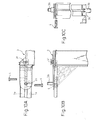
radiator 1 are united to the stays 3j, and both theradiator 1 and thecondenser 2 are secured by fastening the bolts 4'. - According to the present embodiment, as shown in Figs. 9A-9C, the
radiator 1 and thecondenser 2 are secured to thebrackets 3 through the bolts 4' extending parallel to the core surfaces. - According to the present embodiment, as shown in Figs. 10A-10C, the
fan mounting parts 3f are provided on corresponding portions of thebrackets 3 at the ends of theheader tanks - According to the present embodiment, as shown in Fig. 11, the mounting
parts 3b are provided on thebrackets 3 at their parts corresponding to the ends in the longitudinal direction of theheader tanks - Though the
heat exchangers brackets 3 through the bolts in the above embodiments, according to the present embodiment, as shown in Fig. 12, the heat exchanger (thecondenser 2 in Fig. 12) is secured to thebrackets 3 through snap-fits 3h. - The snap-fits constitute a means for detachably securing two members, due to an elastic deformation of projections in the form of hook-shaped pins.
- In the above embodiments, the
bracket bodies 3a are provided between theheader tanks - In the above embodiments, the heat exchanger modules are comprised of the radiator and the condenser, but the present invention is not limited thereto and may be applied to a module comprised of other heat exchangers.
- While the invention has been described by reference to specific embodiments chosen for purposes of illustration, it should be apparent that numerous modifications could be made thereto by those skilled in the art without departing from the basic concept and scope of the invention.
Claims (7)
- A heat exchanger module in which a first heat exchanger and a second heat exchanger are integrated with each other through brackets, said first and second heat exchangers being each constituted by solder-brazing a plurality of tubes and header tanks connected thereto, which are located at opposite ends of the plurality of tubes in the longitudinal direction, wherein
the heat exchangers are arranged with core surfaces thereof being opposed to each other;
the brackets are provided with mounting parts for mounting the heat exchangers to a vehicle; and
the brackets are made of resin and located between the heat exchangers. - A heat exchangers module as set forth in Claim 1, wherein the brackets have the mounting parts and bracket bodies in the form of strip plates,
said bracket bodies being located between the header tanks of the first heat exchanger and the header tanks of the second heat exchanger. - A heat exchanger module as set forth in Claim 1, wherein the brackets have bracket bodies in the form of strip plates and mounting stays, the mounting stays projecting from the end sides of the bracket bodies in the longitudinal direction, in a direction substantially orthogonal to the longitudinal direction of the bracket bodies and provided with the mounting parts on the mounting stays,
said mounting stays are provided on their root sides with reinforcing parts to resist a moment acting on the mounting stays. - A heat exchanger module as set forth in Claim 3, wherein the mounting stays project from the bracket bodies toward the core sides of the heat exchangers,
said reinforcing parts having through holes extending in a direction orthogonal to the core surfaces. - A heat exchanger module as set forth in Claim 1, wherein the brackets are provided on opposite end sides of the heat exchangers, and
at least one of the brackets is secured to the heat exchangers by pin-shaped securing means extending in a direction orthogonal to the core surfaces. - A heat exchanger module as set forth in Claim 2, comprising fan mounting parts, for mounting a fan to move air through the heat exchangers, in the vicinity of the mounting parts.
- A heat exchanger module as set forth in Claim 1, wherein the first and second heat exchangers have channeled inserts which are located on the outermost sides of the plurality of tubes and are each comprised of a bottom surface and two opposite side walls raised from the bottom surface,
said brackets being each provided with a bracket body in the form of a strip plate and a lower mounting stay which projects from the lower end side of the bracket body in the longitudinal direction, in a direction substantially orthogonal to the longitudinal direction of the bracket body and on which the mounting part is provided,
said lower mounting stays having projections which are fitted in the inserts of the heat exchangers, said projections being provided with tapered parts oriented to the bracket body side.
Applications Claiming Priority (2)
| Application Number | Priority Date | Filing Date | Title |
|---|---|---|---|
| JP2002283136A JP4062033B2 (en) | 2002-09-27 | 2002-09-27 | Heat exchanger module |
| JP2002283136 | 2002-09-27 |
Publications (2)
| Publication Number | Publication Date |
|---|---|
| EP1403606A2 true EP1403606A2 (en) | 2004-03-31 |
| EP1403606A3 EP1403606A3 (en) | 2012-04-25 |
Family
ID=31973341
Family Applications (1)
| Application Number | Title | Priority Date | Filing Date |
|---|---|---|---|
| EP03021616A Withdrawn EP1403606A3 (en) | 2002-09-27 | 2003-09-25 | Heat exchanger module |
Country Status (3)
| Country | Link |
|---|---|
| US (1) | US7036561B2 (en) |
| EP (1) | EP1403606A3 (en) |
| JP (1) | JP4062033B2 (en) |
Cited By (1)
| Publication number | Priority date | Publication date | Assignee | Title |
|---|---|---|---|---|
| WO2013026965A1 (en) | 2011-08-22 | 2013-02-28 | Renault S.A.S. | Motor vehicle cooling module |
Families Citing this family (20)
| Publication number | Priority date | Publication date | Assignee | Title |
|---|---|---|---|---|
| DE10207025A1 (en) * | 2002-02-20 | 2003-08-28 | Behr Gmbh & Co | Mounting for vehicle radiator comprises clip at top and pivot at bottom |
| DE10322211A1 (en) * | 2003-05-16 | 2004-12-02 | Modine Manufacturing Co., Racine | heat exchanger block |
| DE10348701A1 (en) * | 2003-10-16 | 2005-05-12 | Behr Gmbh & Co Kg | Arrangement for fixing a heat exchanger to another |
| JP4653816B2 (en) * | 2005-02-17 | 2011-03-16 | ベール ゲーエムベーハー ウント コー カーゲー | Box for receiving a heat exchanger fluid, in particular a heat exchanger for a heat exchanger unit, in particular a heat exchanger unit implemented as a monoblock |
| US20060196647A1 (en) * | 2005-03-02 | 2006-09-07 | Calsonickansei North America, Inc. | Heat Exchanger Having an Integral Air Guide |
| DE102005039090A1 (en) * | 2005-08-06 | 2007-02-08 | Behr Gmbh & Co. Kg | Assembly support system |
| US8011420B2 (en) * | 2006-03-13 | 2011-09-06 | Denso International America, Inc. | Condenser attachment bracket |
| JP2007308131A (en) * | 2006-04-20 | 2007-11-29 | Denso Corp | Motorcycle heat exchanger |
| JP2010032156A (en) * | 2008-07-30 | 2010-02-12 | Denso Corp | Coupling device for heat exchanger, and heat exchange device provided with the same |
| AU2011201083B2 (en) * | 2010-03-18 | 2013-12-05 | Modine Manufacturing Company | Heat exchanger and method of manufacturing the same |
| US9309839B2 (en) | 2010-03-18 | 2016-04-12 | Modine Manufacturing Company | Heat exchanger and method of manufacturing the same |
| US20110240387A1 (en) * | 2010-03-31 | 2011-10-06 | Denso International America, Inc. | Thermal strain reducing mounting brackets for a heat exchanger |
| ITTO20110187A1 (en) * | 2011-03-02 | 2012-09-03 | Denso Thermal Systems Spa | HEAT EXCHANGER OF A VEHICLE, EQUIPPED WITH A PROTECTION GRILL |
| JP5721607B2 (en) * | 2011-11-07 | 2015-05-20 | トヨタ自動車株式会社 | Cooling system |
| CN104937364B (en) | 2013-01-28 | 2019-03-08 | 开利公司 | Multi-tube bundle heat exchange unit with manifold assembly |
| US20150101778A1 (en) * | 2013-10-14 | 2015-04-16 | Hyundai Motor Company | Cooling module for vehicle |
| US10337799B2 (en) | 2013-11-25 | 2019-07-02 | Carrier Corporation | Dual duty microchannel heat exchanger |
| CN106461352B (en) * | 2014-05-08 | 2019-04-12 | 达纳加拿大公司 | Heat exchanger with the bracket that is slidably installed |
| US10293677B2 (en) * | 2016-09-20 | 2019-05-21 | Denso International America, Inc. | Heat exchanger and structure for mounting external component to heat exchanger |
| CN115366659B (en) * | 2021-05-17 | 2024-10-25 | 本田技研工业株式会社 | Heat exchange device for vehicle |
Citations (2)
| Publication number | Priority date | Publication date | Assignee | Title |
|---|---|---|---|---|
| JPH11142084A (en) | 1997-11-11 | 1999-05-28 | Denso Corp | Heat exchanger equipment for vehicles |
| EP1424533A2 (en) * | 2002-09-19 | 2004-06-02 | Denso Corporation | Structure connecting heat exchanger to shroud improving workability in assembling or disassembling them |
Family Cites Families (23)
| Publication number | Priority date | Publication date | Assignee | Title |
|---|---|---|---|---|
| US4763723A (en) * | 1987-04-08 | 1988-08-16 | Modine Manufacturing Company | Mounting bracket construction for vehicular radiators |
| JP3191385B2 (en) * | 1991-07-12 | 2001-07-23 | 株式会社デンソー | Condenser mounting device |
| GB9609440D0 (en) * | 1996-05-04 | 1996-07-10 | Ford Motor Co | Radiator and condenser assembly |
| AU729629B2 (en) * | 1996-08-12 | 2001-02-08 | Calsonic Corporation | Integral-type heat exchanger |
| DE29707571U1 (en) * | 1997-04-26 | 1997-07-10 | Längerer & Reich GmbH, 70794 Filderstadt | Arrangement for connecting two heat exchangers |
| DE19731999A1 (en) * | 1997-07-25 | 1999-02-04 | Laengerer & Reich Gmbh & Co | Cooling module |
| EP0896138B1 (en) * | 1997-08-08 | 2003-04-23 | Kobelco Construction Machinery Co., Ltd. | Cooling apparatus for construction machine |
| JP3223164B2 (en) | 1998-05-12 | 2001-10-29 | 新キャタピラー三菱株式会社 | Engine cooling structure |
| JP2001121941A (en) * | 1999-10-28 | 2001-05-08 | Denso Corp | Vehicle-mounted structure of heat exchanger |
| FR2804501B1 (en) * | 2000-01-28 | 2002-04-12 | Valeo Thermique Moteur Sa | HEAT EXCHANGE MODULE, IN PARTICULAR FOR A MOTOR VEHICLE |
| IT1320540B1 (en) * | 2000-07-18 | 2003-12-10 | Magneti Marelli Climat Srl | PRE-ASSEMBLED FRONT GROUP FOR VEHICLES. |
| FR2812383B1 (en) * | 2000-07-28 | 2003-02-07 | Valeo Thermique Moteur Sa | DEVICE FOR ASSEMBLING AT LEAST ONE EQUIPMENT ON A HEAT EXCHANGER |
| US6318450B1 (en) * | 2000-08-22 | 2001-11-20 | Delphi Technologies, Inc. | Fastener free automotive heat exchanger mounting |
| JP2002081884A (en) * | 2000-09-07 | 2002-03-22 | Denso Corp | Mounting structure of heat exchanger |
| JP2002168588A (en) * | 2000-11-30 | 2002-06-14 | Toyo Radiator Co Ltd | Composite heat exchanger for vehicle |
| DE10061561A1 (en) * | 2000-12-07 | 2002-06-13 | Behr Gmbh & Co | Module carrier for various heat exchangers of a motor vehicle engine |
| JP4447162B2 (en) * | 2000-12-28 | 2010-04-07 | 株式会社ティラド | Connection structure for multiple heat exchangers |
| JP2002257495A (en) * | 2001-02-28 | 2002-09-11 | Toyo Radiator Co Ltd | Connecting structure for a plurality of heat exchangers |
| US6510891B2 (en) * | 2001-04-27 | 2003-01-28 | Delphi Technologies, Inc. | Clip-retainer for heat exchanger |
| US6513579B1 (en) * | 2001-09-27 | 2003-02-04 | Delphi Technologies, Inc. | Post braze heat exchanger mounting and support brackets |
| US6470961B1 (en) * | 2002-01-08 | 2002-10-29 | General Motors Corporation | Condenser, radiator and fan assembly module |
| US6691767B2 (en) * | 2002-06-13 | 2004-02-17 | Delphi Technologies, Inc. | Plastic attachment bracket for metal heat exchanger tank |
| DE10250334A1 (en) * | 2002-10-29 | 2004-05-19 | Modine Manufacturing Co., Racine | Heat exchanger arrangement for motor vehicles |
-
2002
- 2002-09-27 JP JP2002283136A patent/JP4062033B2/en not_active Expired - Fee Related
-
2003
- 2003-09-25 US US10/671,102 patent/US7036561B2/en not_active Expired - Fee Related
- 2003-09-25 EP EP03021616A patent/EP1403606A3/en not_active Withdrawn
Patent Citations (2)
| Publication number | Priority date | Publication date | Assignee | Title |
|---|---|---|---|---|
| JPH11142084A (en) | 1997-11-11 | 1999-05-28 | Denso Corp | Heat exchanger equipment for vehicles |
| EP1424533A2 (en) * | 2002-09-19 | 2004-06-02 | Denso Corporation | Structure connecting heat exchanger to shroud improving workability in assembling or disassembling them |
Cited By (1)
| Publication number | Priority date | Publication date | Assignee | Title |
|---|---|---|---|---|
| WO2013026965A1 (en) | 2011-08-22 | 2013-02-28 | Renault S.A.S. | Motor vehicle cooling module |
Also Published As
| Publication number | Publication date |
|---|---|
| EP1403606A3 (en) | 2012-04-25 |
| JP4062033B2 (en) | 2008-03-19 |
| US7036561B2 (en) | 2006-05-02 |
| JP2004116937A (en) | 2004-04-15 |
| US20040069443A1 (en) | 2004-04-15 |
Similar Documents
| Publication | Publication Date | Title |
|---|---|---|
| US7036561B2 (en) | Heat exchanger module | |
| JP4379967B2 (en) | Double heat exchanger | |
| US6918432B2 (en) | Heat exchanger | |
| JP4300628B2 (en) | Heat exchanger | |
| JP2747379B2 (en) | Heat exchanger | |
| US7044203B2 (en) | Structure connecting heat exchanger to shroud improving workability in assembling or disassembling them | |
| US7640966B2 (en) | Heat exchanger and cooling module having the same | |
| JP3043025B2 (en) | Heat exchanger | |
| US20070144713A1 (en) | Integrated heat exchanger and heat exchanger | |
| US20080000626A1 (en) | Heat exchanger | |
| WO2007088850A1 (en) | Heat exchanger for vehicle | |
| US7147046B2 (en) | Heat exchanger of a multiple type | |
| JP2001124486A (en) | Heat exchanger | |
| US7131488B2 (en) | Heat exchanger module | |
| US20020134529A1 (en) | Heat exchanger | |
| JP2000283690A (en) | Heat exchanger | |
| JPH10103893A (en) | Heat exchange equipment | |
| JPH0930246A (en) | Vehicle heat exchange device | |
| KR20000017618A (en) | Plate-fin type heat exchanger and method for manufacturing the same | |
| JP2006284107A (en) | Heat exchanger | |
| JP2989855B2 (en) | Double heat exchanger | |
| JPH09257388A (en) | Heat exchanger | |
| JP2898800B2 (en) | Heat exchanger | |
| JP3922164B2 (en) | Double heat exchanger | |
| JPH08159686A (en) | Laminate type heat exchanger core |
Legal Events
| Date | Code | Title | Description |
|---|---|---|---|
| PUAI | Public reference made under article 153(3) epc to a published international application that has entered the european phase |
Free format text: ORIGINAL CODE: 0009012 |
|
| AK | Designated contracting states |
Kind code of ref document: A2 Designated state(s): AT BE BG CH CY CZ DE DK EE ES FI FR GB GR HU IE IT LI LU MC NL PT RO SE SI SK TR |
|
| AX | Request for extension of the european patent |
Extension state: AL LT LV MK |
|
| PUAL | Search report despatched |
Free format text: ORIGINAL CODE: 0009013 |
|
| AK | Designated contracting states |
Kind code of ref document: A3 Designated state(s): AT BE BG CH CY CZ DE DK EE ES FI FR GB GR HU IE IT LI LU MC NL PT RO SE SI SK TR |
|
| AX | Request for extension of the european patent |
Extension state: AL LT LV MK |
|
| RIC1 | Information provided on ipc code assigned before grant |
Ipc: F28F 9/00 20060101ALI20120320BHEP Ipc: F28D 1/04 20060101AFI20120320BHEP |
|
| 17P | Request for examination filed |
Effective date: 20120712 |
|
| AKX | Designation fees paid |
Designated state(s): DE FR GB |
|
| 17Q | First examination report despatched |
Effective date: 20130912 |
|
| STAA | Information on the status of an ep patent application or granted ep patent |
Free format text: STATUS: THE APPLICATION IS DEEMED TO BE WITHDRAWN |
|
| 18D | Application deemed to be withdrawn |
Effective date: 20140123 |