EP1403484A1 - A vehicle comprising a sound insulation structure - Google Patents
A vehicle comprising a sound insulation structure Download PDFInfo
- Publication number
- EP1403484A1 EP1403484A1 EP20030020795 EP03020795A EP1403484A1 EP 1403484 A1 EP1403484 A1 EP 1403484A1 EP 20030020795 EP20030020795 EP 20030020795 EP 03020795 A EP03020795 A EP 03020795A EP 1403484 A1 EP1403484 A1 EP 1403484A1
- Authority
- EP
- European Patent Office
- Prior art keywords
- sound insulation
- insulation cover
- openings
- vehicle
- cover
- Prior art date
- Legal status (The legal status is an assumption and is not a legal conclusion. Google has not performed a legal analysis and makes no representation as to the accuracy of the status listed.)
- Granted
Links
- 238000009413 insulation Methods 0.000 title claims abstract description 81
- 238000001816 cooling Methods 0.000 claims abstract description 68
- 230000002093 peripheral effect Effects 0.000 claims abstract description 26
- 230000000903 blocking effect Effects 0.000 abstract description 2
- 230000005540 biological transmission Effects 0.000 description 13
- 230000006866 deterioration Effects 0.000 description 4
- 239000011358 absorbing material Substances 0.000 description 3
- 230000007246 mechanism Effects 0.000 description 2
- 230000009467 reduction Effects 0.000 description 2
- 230000004888 barrier function Effects 0.000 description 1
- 239000000498 cooling water Substances 0.000 description 1
- 230000000694 effects Effects 0.000 description 1
- 238000004519 manufacturing process Methods 0.000 description 1
- 230000013011 mating Effects 0.000 description 1
Images




Classifications
-
- F—MECHANICAL ENGINEERING; LIGHTING; HEATING; WEAPONS; BLASTING
- F02—COMBUSTION ENGINES; HOT-GAS OR COMBUSTION-PRODUCT ENGINE PLANTS
- F02B—INTERNAL-COMBUSTION PISTON ENGINES; COMBUSTION ENGINES IN GENERAL
- F02B77/00—Component parts, details or accessories, not otherwise provided for
- F02B77/11—Thermal or acoustic insulation
- F02B77/13—Acoustic insulation
-
- F—MECHANICAL ENGINEERING; LIGHTING; HEATING; WEAPONS; BLASTING
- F02—COMBUSTION ENGINES; HOT-GAS OR COMBUSTION-PRODUCT ENGINE PLANTS
- F02B—INTERNAL-COMBUSTION PISTON ENGINES; COMBUSTION ENGINES IN GENERAL
- F02B61/00—Adaptations of engines for driving vehicles or for driving propellers; Combinations of engines with gearing
- F02B61/02—Adaptations of engines for driving vehicles or for driving propellers; Combinations of engines with gearing for driving cycles
Definitions
- the present invention relates to a vehicle, in particular a motorcycle, comprising a sound insulation structure for a forced air cooling engine.
- a swing type engine unit including a forced air cooling engine and a V belt type continuously variable transmission may be mounted.
- this type of forced air cooling engine the circumference of a cylinder head including an external end of a crankshaft is surrounded by an air shroud substantially airtightly, an air suction port is formed in a part of the air shroud facing the external end of the crankshaft, and a cooling fan is attached to the external end of the crankshaft. Then, cooling air is sucked from the air suction port by the cooling fan to be forcibly supplied to the circumference of the cylinder head.
- the present invention has been devised in view of the above-mentioned circumstances, and it is an object of the present invention to provide a vehicle comprising a sound insulation structure for a forced air cooling engine, wherein the sound insulation structure is improved in cooling characteristic and production cost thereof.
- a vehicle in particular a motorcycle, comprising a sound insulation structure for a forced air cooling engine, wherein said sound insulation structure comprises a sound insulation cover, and said sound insulation cover comprises wind introducing means at different side walls side walls thereof.
- said side walls are angled to each other.
- said wind introducing means are formed by a running wind introducing port and openings, wherein said running wind introducing port is arranged in a driving direction and said openings are arranged perpendicularly thereto.
- said sound insulation structure can attain both the guiding of cooling air and the sound insulation with one component without increasing the number of components.
- said sound insulation cover is generally bowl-like, and said side walls consist of a side peripheral wall and of a cover-like external side wall, wherein said openings are provided on said cover-like external side wall.
- said openings are generally oblong rectangular-shaped and extend in a longitudinal direction of said sound insulation cover.
- louvers extending obliquely upward to an inner side of said sound insulation cover are provided, wherein said louvers are formed at lower edges of said openings, and upper edges of said louvers are located at a height substantially the same as that of upper edges of said openings.
- the engine is not visible by a view from above of the sound insulation cover and foreign bodies are prevented from entering the sound insulation cover.
- said side peripheral wall of said sound insulation cover is substantially parallel to a rear edge of a body cover of said vehicle, so that foreign bodies are also prevented from entering inside of the sound insulation cover.
- a body frame of said vehicle is located in front of said running wind introducing port of said sound insulation cover.
- an air shroud airtightly surrounds a cylinder block and a cylinder head and comprises a cooling air suction portion formed in a part of said air shroud and a cooling air discharge port formed in a part of said cylinder block, wherein said sound insulation cover covers said cooling air suction port of said air shroud.
- a flat section for avoiding interference with an exhaust pipe is formed on a lower surface of said side peripheral wall of said sound insulation cover, so that the sound insulation cover is protected from damage through the heat of the exhaust pipe.
- the sound insulation cover is attached to the outside of the suction port of the air shroud, the rectangular openings extending in the longitudinal direction of the vehicle are formed on the external side wall of the sound insulation cover, the louvers extending obliquely upward to the inner side in the crankshaft direction are formed at the lower edges of the openings. Therefore, the cooling air is sucked into the air shroud from the openings along the louvers, and the cooling air can be sent to a cylinder section smoothly.
- the openings can be substantially covered by the louvers, and the cooling fan in the sound insulation cover is never seen from upper and side positions of the vehicle, whereby deterioration of an appearance in the case in which the openings are formed on the external side wall of the sound insulation cover can be controlled.
- the running wind introducing port which is opened toward the front of the vehicle, is formed on the side peripheral wall of the sound insulation cover, cooling water during traveling can be introduced into the air shroud together with the cooling air from the openings of the external side wall, whereby a cooling efficiency of the engine can be improved.
- fan noises from the running wind introducing port tend to be absorbed by running wind sucked from the running wind introducing port, noises can be reduced.
- the running wind introducing port is opened in the body cover, and the peripheral edge of the running wind introducing port is formed so as to be in parallel with the rear edge of the body cover, the running wind introducing port is never seen from the sides of the vehicle, whereby deterioration of an appearance can be prevented.
- fan noises are discharged into the body cover from the running wind introducing port, the fan noises are hardly heard from the outside, as a result, noises can be reduced and, moreover, suction sound of running wind can be prevented from leaking to the outside.
- the body frame is located in front of the running wind introducing port, a foreign body can be prevented from entering the sound insulation cover from the running wind introducing port without providing the specific shield.
- Figs. 1 to 8 are views for explaining a sound insulation structure for a forced air cooling engine according to one embodiment of the present invention.
- Fig. 1 is a side view of a scooter type motorcycle mounted with the forced air cooling engine
- Fig. 2 is a sectional plan view of the forced air cooling engine
- Figs. 3, 4, and 5 are a side view, a rear view, and a bottom view showing a mounting state of a sound insulation cover, respectively
- Fig. 6 is a side view of the sound insulation cover
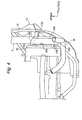
- Figs. 7 and 8 are sectional views (sectional views along line VII-VII and line VIII-VIII of Fig. 6) of the sound insulation cover.
- reference numeral 1 denotes a scooter type motorcycle, which is schematically of a structure in which a front fork 3 is supported pivotably to the left and right on a front end of an underbone type body frame 2 by a head pipe (not shown), a front wheel 4 is disposed at a lower end of the front fork 3, a steering handlebar 5 is disposed at an upper end thereof, a seat 6 is disposed in a central part in a longitudinal direction of the body frame 2, a swing type engine unit 7 is disposed under the seat 6 so as to be able to swing vertically, and a rear wheel 8 is disposed at a rear end of the engine unit 7.
- a front side of the front fork 3 of the body frame 2 is surrounded by a front cover 9 and a rear side thereof is surrounded by a leg shield 10, and the steering handlebar 5 is surrounded by a handle cover 11.
- a foot board 12 on which rider's feed are placed is disposed at a lower end of the leg shield 10, and a lower part of the seat 6 is surrounded by left and right side covers 13.
- the side covers 13 are divided into under covers 14 covering a lower side of the foot board 12 and upper covers 15 covering the lower part of the seat 6.
- Rear edges 13a of the side covers 13 rise obliquely upward from rear ends of the under covers 14 to central parts in the longitudinal direction of lower edges of the side covers 13.
- the engine unit 7 is of a structure in which a V belt type continuously variable transmission 21 is integrally coupled to a left side part in a vehicle width direction of a forced air cooling engine 20.
- This forced air cooling engine 20 is an engine of a two cycle single cylinder type and is of a structure in which a cylinder block 24 with plural cooling fins 24a integrally formed is coupled to a front side mating surface of a crank case 23 containing a crankshaft 22, which is arranged horizontally in the vehicle width direction and a cylinder head 25 is coupled to the cylinder block 24.
- An exhaust port (not shown) is opened in a lower surface wall of the cylinder block 24, and an exhaust pipe 29 is connected to the exhaust port.
- This exhaust pipe 29 extends to the right side in the crankshaft direction through a lower side of the crank case 23 from the cylinder block 24 and extends in a rear direction of the vehicle from the right side end, and a muffler 29a, which is disposed on the right side of the rear wheel 8, is connected to the rear end.
- a transmission case 30 extending to the rear of the vehicle is integrally formed on the left side part in the crankshaft direction of the crank case 23, and a case cover 31 is bolted and fixed to the vehicle exterior side of the transmission case 30.
- the -V belt type continuously variable transmission 21 is contained in a belt chamber formed by the transmission case 30 and the case cover 31.
- This continuously variable transmission 21 is formed in a structure in which a V belt 36 is wound around a drive pulley 33, which is attached to a left side end of the crankshaft 22, and a driven pulley 35, which is attached to a transmission shaft 34 disposed in parallel with the crankshaft 22 at a rear end of the transmission case 30, and a centrifugal clutch 37 is attached to an outer side of the driven pulley 35 on the transmission shaft 34.
- a rear wheel drive shaft 41 to which the rear wheel 8 is adhered with the intervention of a deceleration mechanism 40, is disposed in parallel with the crankshaft 22 behind the transmission shaft 34.
- crankshaft 22 rotation of the crankshaft 22 is constantly transmitted from the drive pulley 33 to the driven pulley 35 and, when the rotation of the crankshaft 22 increases, rotation of the driven pulley 35 is transmitted to the transmission shaft 34 via the centrifugal clutch 37 and is transmitted from the transmission shaft 34 to the rear wheel drive shaft 41 via the deceleration mechanism 40.
- An air shroud 45 which airtightly surrounds the cylinder block 24 and the cylinder head 25, is attached and fixed to a part extending from a right side end of the crankshaft 22 including the right side end to the cylinder block 24 and the cylinder head 25.
- a cooling air suction portion 45a is formed in a part of this air shroud 45 facing the right side end in the crankshaft direction, and a cooling air discharge port 45b is formed in a part of the cylinder block 24 facing the cooling fins 24a.
- a generator 47 is mounted on the right side end of the crankshaft 22 so as to rotate together with the crankshaft 22, and a cooling fan 46 is formed on an external surface of the generator 47.
- cooling air is sucked from the cooling air suction portion 45a, and this cooling air flows inside the air shroud 45 while cooling the cylinder block 24 and the cylinder head 25 and is discharged to the outside from the discharge port 45b (see arrow of Fig. 2).
- a sound insulation cover 50 is disposed on the vehicle exterior side in the crankshaft direction of the cooling air suction port 45a of the air shroud 45.
- This sound insulation cover 50 is a substantially bowl-like cover constituted by integrally forming a side peripheral wall 50a, which is formed so as to airtightly surround an external peripheral part of the cooling air suction port 45a, and a cover-like external side wall 50b, which blocks the vehicle exterior side of the side peripheral wall 50a.
- Flange section 50c are formed at an opening edge of the side peripheral wall 50a. Each of these flange sections 50c is fastened and fixed to a boss section 45d of the air shroud 45 by a fixing screw 51.
- a flat section 50d for avoiding interference with the exhaust pipe 29 is formed on a lower surface of the side peripheral wall 50a of the sound insulation cover 50. Consequently, the sound insulation cover 50 is prevented from being overheated by heat from the exhaust pipe 29.
- a running wind introducing port 50e which opens toward the front of the vehicle, is formed on the side peripheral wall 50a of the sound insulation cover 50.
- This running wind introducing port 50e inclines so as to define an angle of approximately 25 degrees with respect to a vertical line, and opens into the side covers 13.
- a peripheral part of the running wind introducing port 50e is in parallel with the rear edges 13a of the side covers 13.
- a seat rail section 2a of the body frame 2 is arranged in front of the running wind introducing port 50e.
- the body frame 2 mainly includes an under pipe section extending from the head pipe in the lower rear direction, a foot rest section extending in the rear direction from a rear end of the under pipe section substantially horizontally, and the seat rail section 2a extending obliquely upward from a rear end of the foot rest section.
- openings 52, 53 extending in the longitudinal direction of the vehicle are formed in parallel in the vertical direction on the external side wall 50b of the sound insulation cover 50.
- the upper three openings 52 are formed so as to generally have an oblong rectangular shape
- the opening 53 at the lowermost end is formed so as to generally have an arc shape.
- louvers 54 which extend obliquely upward to the inner side in the crankshaft direction, that is, into the sound insulation cover 50, are integrally formed.
- An inclination angle of the respective louvers 54 is set to generally 50 to 60 degrees.
- upper edges 54a of the respective louvers 54 are set in a position of the same height as the upper edges 52b of the rectangular openings 52. Consequently, when viewed from upper and side positions outside the vehicle, the respective rectangular openings 52 are blocked by the louvers 54.
- a louver 55 which extends vertically upward after extending in the rear direction from the lower edge 53a, is formed, and an upper edge 55a of the louver 55 is located at a height which is the same as that of the upper edge 53b of the arc-shaped opening 53.
- the cooling fan 46 rotates in accordance with the rotation of the crankshaft 22 and, at the time of idling drive, cooling air is mainly sucked from the respective openings 52, 53 of the sound insulation cover 50.
- suction sound of the cooling fan 46 hits the inner surface of the louvers 54 and the inner surface of the external side wall 50b and is discharged downward to the outside of the vehicle from the rectangular openings 52 along the external surface of the louver 54 located on the lower side of the sound insulation cover 50.
- the rotation of the cooling fan 46 increases as the rotation of the crankshaft 22 increases, whereby cooling air is sucked from the respective openings 52, 53 of the sound insulation cover 50 and, at the same time, running wind is sucked from the running wind introducing port 50e.
- noises of the running wind introducing port 50e are shut up in the sound insulation cover 50 by the cooling air sucked from the introducing port 50e, and discharge of the noises to the outside can be controlled.
- the bowl-like sound insulation cover 50 having the side peripheral wall 50a and the external side wall 50b is attached to the vehicle exterior side of the cooling air suction port 45a of the air shroud 45, the oblong rectangular openings 52 extending in the longitudinal direction of the vehicle are formed on the external side wall 50b of the sound insulation cover 50, and the louvers 54 extending obliquely upward into the sound insulation cover 50 are integrally formed at lower edges 52a of the respective rectangular openings 52.
- cooling air is introduced into the sound insulation cover 50 from the respective openings 52 along the louvers 54, supplied to the cooling fins 24a of the cylinder head 24 through the air shroud 45, and discharged to the outside from the discharge port 45b after heat exchange is performed.
- noises such as suction sound generated by the cooling fan 46 and engine sound hit the inner surfaces of the louvers 54 and the external side wall 50b of the sound insulation cover 50 and, then, are discharged downward to the outside of the vehicle from the openings 52 along the respective louvers 54, whereby the noises can be discharged toward the ground receding into the distance from the rider and can be reduced substantially.
- both the guidance of the cooling air and the reduction of noises can be achieved by one sound insulation cover 50 without increasing the number of components, and cost can be reduced compared with the conventional case in which two components are mounted.
- the openings 52 can be covered substantially by the louvers 54, and the cooling fan 46 in the sound insulation cover 50 is never seen from upper and side positions of the vehicle, whereby deterioration of an appearance caused by forming the openings 52 can be prevented.
- the running wind introducing port 50e opening to the front of the vehicle is formed in the side peripheral wall 50a of the sound insulation cover 50, cooling air during traveling can be introduced into the air shroud 45 together with cooling air from the respective openings 52 of the external side wall 50b, and a cooling efficiency of the engine 20 can be improved.
- fan noises or the like from the running wind introducing port 50e can be shut up in the sound insulation cover 50 by running wind sucked from the introducing port 50e, an effect of reducing noises can be improved.
- the peripheral edge of the running wind introducing port 50e is formed so as to be parallel with the rear edges 13a of the side covers 13, and the running wind introducing port 50e is also opened into the side covers 13, the running wind introducing port 50e is never seen from the sides of the vehicle, whereby deterioration of an appearance can be prevented, and suction sound of running wind can be prevented from leaking to the outside.
- the seat rail section 2a of the body frame 2 is arranged in front of the running wind introducing port 50e, a foreign body can be prevented from entering the sound insulation cover 50 from the running wind introducing port 50e without providing the specific shield.
- an air suction port is formed in a part of an air shroud, which is formed so as to airtightly surround a cylinder portion including an external end of a crankshaft arranged toward a vehicle width direction, facing an external end of the crankshaft and a cooling fan is attached to the external end of the crankshaft, wherein a generally bowl-like sound insulation cover, which has a side peripheral wall surrounding an external peripheral part of the suction port and an external side wall blocking a vehicle exterior side of the side peripheral wall, is attached to the vehicle exterior side of the air suction port, openings of a generally oblong rectangular shape extending in a longitudinal direction of vehicle are formed in the external side wall, louvers extending obliquely upward to an inner side in a crankshaft direction are formed at lower edges of the openings, and upper edges of the louvers are located at a height substantially the same as that of upper edges of the openings.
- a running wind introducing port which is opened toward the front of the vehicle, is formed in the side peripheral wall of the sound insulation cover.
- the running wind introducing port is opened in a body cover and, when viewed from the vehicle exterior side in the crankshaft direction, a peripheral edge of the running wind introducing port is formed so as to be in parallel with a rear edge of the body cover.
- the body frame is located in front of the running wind introducing port of the sound insulation cover.
Landscapes
- Engineering & Computer Science (AREA)
- Chemical & Material Sciences (AREA)
- Combustion & Propulsion (AREA)
- Mechanical Engineering (AREA)
- General Engineering & Computer Science (AREA)
- Physics & Mathematics (AREA)
- Acoustics & Sound (AREA)
- General Details Of Gearings (AREA)
- Automatic Cycles, And Cycles In General (AREA)
- Vehicle Interior And Exterior Ornaments, Soundproofing, And Insulation (AREA)
Abstract
Description
- The present invention relates to a vehicle, in particular a motorcycle, comprising a sound insulation structure for a forced air cooling engine.
- For example, in a scooter type motorcycle, a swing type engine unit including a forced air cooling engine and a V belt type continuously variable transmission may be mounted. In this type of forced air cooling engine, the circumference of a cylinder head including an external end of a crankshaft is surrounded by an air shroud substantially airtightly, an air suction port is formed in a part of the air shroud facing the external end of the crankshaft, and a cooling fan is attached to the external end of the crankshaft. Then, cooling air is sucked from the air suction port by the cooling fan to be forcibly supplied to the circumference of the cylinder head.
- Incidentally, in the above-mentioned forced air cooling engine, since noises due to suction sound of the cooling fan at the time of normal drive including idling causes a problem, the noises are prevented from leaking to the outside of a vehicle as much as possible. Therefore, there have been proposed a forced air cooling engine with a structure in which an air suction port of an air shroud is covered by an external cover, see JP-B-6-29552, and a forced air cooling engine with a structure in which a suction port of an air shroud is covered by a cover to which a sound absorbing material is adhered, see JP-A-06-212995.
- However, in the sound insulation structure described in the above-mentioned gazettes issued in the past, there is a problem in that the external cover or the cover serving as a sound barrier and an air guide (louver) for guiding the air into the air shroud are separate components, and the number of components is increased. In addition, there is a problem in that the number of components increases so much more for adhering the sound absorbing material to an inner surface of the cover.
- The present invention has been devised in view of the above-mentioned circumstances, and it is an object of the present invention to provide a vehicle comprising a sound insulation structure for a forced air cooling engine, wherein the sound insulation structure is improved in cooling characteristic and production cost thereof.
- The objective is solved according to the present invention by a vehicle, in particular a motorcycle, comprising a sound insulation structure for a forced air cooling engine, wherein said sound insulation structure comprises a sound insulation cover, and said sound insulation cover comprises wind introducing means at different side walls side walls thereof.
- Preferred, said side walls are angled to each other.
- According to a preferred embodiment, said wind introducing means are formed by a running wind introducing port and openings, wherein said running wind introducing port is arranged in a driving direction and said openings are arranged perpendicularly thereto.
- Thus, said sound insulation structure can attain both the guiding of cooling air and the sound insulation with one component without increasing the number of components.
- According to still a further preferred embodiment, said sound insulation cover is generally bowl-like, and said side walls consist of a side peripheral wall and of a cover-like external side wall, wherein said openings are provided on said cover-like external side wall.
- According to another preferred embodiment, said openings are generally oblong rectangular-shaped and extend in a longitudinal direction of said sound insulation cover.
- According to a further preferred embodiment, louvers extending obliquely upward to an inner side of said sound insulation cover are provided, wherein said louvers are formed at lower edges of said openings, and upper edges of said louvers are located at a height substantially the same as that of upper edges of said openings.
- Thus, the engine is not visible by a view from above of the sound insulation cover and foreign bodies are prevented from entering the sound insulation cover.
- According to another preferred embodiment, said side peripheral wall of said sound insulation cover is substantially parallel to a rear edge of a body cover of said vehicle, so that foreign bodies are also prevented from entering inside of the sound insulation cover.
- According to a further preferred embodiment, a body frame of said vehicle is located in front of said running wind introducing port of said sound insulation cover.
- According to a further preferred embodiment, an air shroud airtightly surrounds a cylinder block and a cylinder head and comprises a cooling air suction portion formed in a part of said air shroud and a cooling air discharge port formed in a part of said cylinder block, wherein said sound insulation cover covers said cooling air suction port of said air shroud.
- According to a further preferred embodiment, a flat section for avoiding interference with an exhaust pipe is formed on a lower surface of said side peripheral wall of said sound insulation cover, so that the sound insulation cover is protected from damage through the heat of the exhaust pipe.
- Preferred, the sound insulation cover is attached to the outside of the suction port of the air shroud, the rectangular openings extending in the longitudinal direction of the vehicle are formed on the external side wall of the sound insulation cover, the louvers extending obliquely upward to the inner side in the crankshaft direction are formed at the lower edges of the openings. Therefore, the cooling air is sucked into the air shroud from the openings along the louvers, and the cooling air can be sent to a cylinder section smoothly. On the other hand, since noises due to suction sound or the like of the cooling fan are discharged downward to the outside of the vehicle along the louvers after hitting the inner surface on the external side wall of the sound insulation cover, the noises can be discharged toward a direction in which the noises fades away from a rider and can be reduced. As a result, both the guidance of the cooling air and the reduction of noises can be achieved by one sound insulation cover without increasing the number of parts, and the sound absorbing material can be made unnecessary, whereby increase in cost can be controlled.
- In addition, since the upper edges of the louvers are located at the height substantially the same as that of the upper edges of the openings, the openings can be substantially covered by the louvers, and the cooling fan in the sound insulation cover is never seen from upper and side positions of the vehicle, whereby deterioration of an appearance in the case in which the openings are formed on the external side wall of the sound insulation cover can be controlled.
- Moreover, since the running wind introducing port, which is opened toward the front of the vehicle, is formed on the side peripheral wall of the sound insulation cover, cooling water during traveling can be introduced into the air shroud together with the cooling air from the openings of the external side wall, whereby a cooling efficiency of the engine can be improved. In addition, since fan noises from the running wind introducing port tend to be absorbed by running wind sucked from the running wind introducing port, noises can be reduced.
- Additionally, since the running wind introducing port is opened in the body cover, and the peripheral edge of the running wind introducing port is formed so as to be in parallel with the rear edge of the body cover, the running wind introducing port is never seen from the sides of the vehicle, whereby deterioration of an appearance can be prevented. In addition, since fan noises are discharged into the body cover from the running wind introducing port, the fan noises are hardly heard from the outside, as a result, noises can be reduced and, moreover, suction sound of running wind can be prevented from leaking to the outside.
- Furthermore, since the body frame is located in front of the running wind introducing port, a foreign body can be prevented from entering the sound insulation cover from the running wind introducing port without providing the specific shield.
- Further preferred embodiments of the present invention are laid down in the further subclaims.
- In the following, the present invention is explained in greater detail by means of several embodiments thereof in conjunction with the accompanying drawings, wherein:
- Fig. 1
- is a side view of a scooter type motorcycle mounted with a forced air cooling engine according to an embodiment of the present invention;
- Fig. 2
- is a sectional plan view of the forced air cooling engine;
- Fig. 3
- is a side view of a sound insulation cover mounted on the forced air cooling engine;
- Fig. 4
- is a rear view showing a mounting state of the sound insulation cover;
- Fig. 5
- is a bottom view showing the mounting state of the sound insulation cover;
- Fig. 6
- is a side view of the sound insulation cover;
- Fig. 7
- is a sectional view (sectional view along line VII-VII of Fig. 6) of the sound insulation cover; and
- Fig. 8
- is a sectional view (sectional view along line VIII-VIII of Fig. 6) of the sound insulation cover.
- Figs. 1 to 8 are views for explaining a sound insulation structure for a forced air cooling engine according to one embodiment of the present invention. Fig. 1 is a side view of a scooter type motorcycle mounted with the forced air cooling engine, Fig. 2 is a sectional plan view of the forced air cooling engine, Figs. 3, 4, and 5 are a side view, a rear view, and a bottom view showing a mounting state of a sound insulation cover, respectively, Fig. 6 is a side view of the sound insulation cover, and Figs. 7 and 8 are sectional views (sectional views along line VII-VII and line VIII-VIII of Fig. 6) of the sound insulation cover.
- In the figures,
reference numeral 1 denotes a scooter type motorcycle, which is schematically of a structure in which afront fork 3 is supported pivotably to the left and right on a front end of an underbone type body frame 2 by a head pipe (not shown), a front wheel 4 is disposed at a lower end of thefront fork 3, a steering handlebar 5 is disposed at an upper end thereof, a seat 6 is disposed in a central part in a longitudinal direction of the body frame 2, a swingtype engine unit 7 is disposed under the seat 6 so as to be able to swing vertically, and arear wheel 8 is disposed at a rear end of theengine unit 7. - A front side of the
front fork 3 of the body frame 2 is surrounded by afront cover 9 and a rear side thereof is surrounded by aleg shield 10, and the steering handlebar 5 is surrounded by ahandle cover 11. In addition, afoot board 12 on which rider's feed are placed is disposed at a lower end of theleg shield 10, and a lower part of the seat 6 is surrounded by left and right side covers 13. - The
side covers 13 are divided into undercovers 14 covering a lower side of thefoot board 12 andupper covers 15 covering the lower part of the seat 6.Rear edges 13a of the side covers 13 rise obliquely upward from rear ends of the undercovers 14 to central parts in the longitudinal direction of lower edges of theside covers 13. - The
engine unit 7 is of a structure in which a V belt type continuouslyvariable transmission 21 is integrally coupled to a left side part in a vehicle width direction of a forcedair cooling engine 20. - This forced
air cooling engine 20 is an engine of a two cycle single cylinder type and is of a structure in which acylinder block 24 withplural cooling fins 24a integrally formed is coupled to a front side mating surface of acrank case 23 containing acrankshaft 22, which is arranged horizontally in the vehicle width direction and acylinder head 25 is coupled to thecylinder block 24. Apiston 27, which is coupled to thecrankshaft 22 via a connectingrod 26, is slidably inserted and arranged in thecylinder block 24, and anignition plug 28 is inserted in thecylinder head 25. - An exhaust port (not shown) is opened in a lower surface wall of the
cylinder block 24, and anexhaust pipe 29 is connected to the exhaust port. Thisexhaust pipe 29 extends to the right side in the crankshaft direction through a lower side of thecrank case 23 from thecylinder block 24 and extends in a rear direction of the vehicle from the right side end, and amuffler 29a, which is disposed on the right side of therear wheel 8, is connected to the rear end. - A
transmission case 30 extending to the rear of the vehicle is integrally formed on the left side part in the crankshaft direction of thecrank case 23, and acase cover 31 is bolted and fixed to the vehicle exterior side of thetransmission case 30. The -V belt type continuouslyvariable transmission 21 is contained in a belt chamber formed by thetransmission case 30 and thecase cover 31. - This continuously
variable transmission 21 is formed in a structure in which aV belt 36 is wound around adrive pulley 33, which is attached to a left side end of thecrankshaft 22, and a drivenpulley 35, which is attached to atransmission shaft 34 disposed in parallel with thecrankshaft 22 at a rear end of thetransmission case 30, and acentrifugal clutch 37 is attached to an outer side of the drivenpulley 35 on thetransmission shaft 34. In addition, a rearwheel drive shaft 41, to which therear wheel 8 is adhered with the intervention of adeceleration mechanism 40, is disposed in parallel with thecrankshaft 22 behind thetransmission shaft 34. Further, rotation of thecrankshaft 22 is constantly transmitted from thedrive pulley 33 to the drivenpulley 35 and, when the rotation of thecrankshaft 22 increases, rotation of the drivenpulley 35 is transmitted to thetransmission shaft 34 via the centrifugal clutch 37 and is transmitted from thetransmission shaft 34 to the rearwheel drive shaft 41 via thedeceleration mechanism 40. - Next, the sound insulation structure of the above-mentioned forced
air cooling engine 20 will be described. - An
air shroud 45, which airtightly surrounds thecylinder block 24 and thecylinder head 25, is attached and fixed to a part extending from a right side end of thecrankshaft 22 including the right side end to thecylinder block 24 and thecylinder head 25. A coolingair suction portion 45a is formed in a part of thisair shroud 45 facing the right side end in the crankshaft direction, and a coolingair discharge port 45b is formed in a part of thecylinder block 24 facing thecooling fins 24a. - A
generator 47 is mounted on the right side end of thecrankshaft 22 so as to rotate together with thecrankshaft 22, and a coolingfan 46 is formed on an external surface of thegenerator 47. When the coolingfan 46 rotates according to the rotation of thecrankshaft 22, cooling air is sucked from the coolingair suction portion 45a, and this cooling air flows inside theair shroud 45 while cooling thecylinder block 24 and thecylinder head 25 and is discharged to the outside from thedischarge port 45b (see arrow of Fig. 2). - A
sound insulation cover 50 is disposed on the vehicle exterior side in the crankshaft direction of the coolingair suction port 45a of theair shroud 45. Thissound insulation cover 50 is a substantially bowl-like cover constituted by integrally forming a sideperipheral wall 50a, which is formed so as to airtightly surround an external peripheral part of the coolingair suction port 45a, and a cover-likeexternal side wall 50b, which blocks the vehicle exterior side of the sideperipheral wall 50a.Flange section 50c are formed at an opening edge of the sideperipheral wall 50a. Each of theseflange sections 50c is fastened and fixed to aboss section 45d of theair shroud 45 by a fixingscrew 51. - A
flat section 50d for avoiding interference with theexhaust pipe 29 is formed on a lower surface of the sideperipheral wall 50a of thesound insulation cover 50. Consequently, thesound insulation cover 50 is prevented from being overheated by heat from theexhaust pipe 29. - A running
wind introducing port 50e, which opens toward the front of the vehicle, is formed on the sideperipheral wall 50a of thesound insulation cover 50. This runningwind introducing port 50e inclines so as to define an angle of approximately 25 degrees with respect to a vertical line, and opens into the side covers 13. In addition, when viewed from the side of the vehicle, a peripheral part of the runningwind introducing port 50e is in parallel with therear edges 13a of the side covers 13. - In addition, a
seat rail section 2a of the body frame 2 is arranged in front of the runningwind introducing port 50e. Here, although not shown, the body frame 2 mainly includes an under pipe section extending from the head pipe in the lower rear direction, a foot rest section extending in the rear direction from a rear end of the under pipe section substantially horizontally, and theseat rail section 2a extending obliquely upward from a rear end of the foot rest section. - Four
openings external side wall 50b of thesound insulation cover 50. Among them, the upper threeopenings 52 are formed so as to generally have an oblong rectangular shape, and theopening 53 at the lowermost end is formed so as to generally have an arc shape. - At
lower edges 52a of the respectiverectangular openings 52,louvers 54, which extend obliquely upward to the inner side in the crankshaft direction, that is, into thesound insulation cover 50, are integrally formed. An inclination angle of therespective louvers 54 is set to generally 50 to 60 degrees. Moreover,upper edges 54a of therespective louvers 54 are set in a position of the same height as theupper edges 52b of therectangular openings 52. Consequently, when viewed from upper and side positions outside the vehicle, the respectiverectangular openings 52 are blocked by thelouvers 54. - In addition, at a
lower edge 53a of the arc-shapedopening 53, alouver 55, which extends vertically upward after extending in the rear direction from thelower edge 53a, is formed, and anupper edge 55a of thelouver 55 is located at a height which is the same as that of theupper edge 53b of the arc-shapedopening 53. - Next, actions and advantages of this embodiment will be described.
- During engine drive, the cooling
fan 46 rotates in accordance with the rotation of thecrankshaft 22 and, at the time of idling drive, cooling air is mainly sucked from therespective openings sound insulation cover 50. On the other hand, suction sound of the coolingfan 46 hits the inner surface of thelouvers 54 and the inner surface of theexternal side wall 50b and is discharged downward to the outside of the vehicle from therectangular openings 52 along the external surface of thelouver 54 located on the lower side of thesound insulation cover 50. - At the time of traveling, the rotation of the cooling
fan 46 increases as the rotation of thecrankshaft 22 increases, whereby cooling air is sucked from therespective openings sound insulation cover 50 and, at the same time, running wind is sucked from the runningwind introducing port 50e. In this case, noises of the runningwind introducing port 50e are shut up in thesound insulation cover 50 by the cooling air sucked from the introducingport 50e, and discharge of the noises to the outside can be controlled. - In this way, according to the sound insulation structure of this embodiment, the bowl-like
sound insulation cover 50 having the sideperipheral wall 50a and theexternal side wall 50b is attached to the vehicle exterior side of the coolingair suction port 45a of theair shroud 45, the oblongrectangular openings 52 extending in the longitudinal direction of the vehicle are formed on theexternal side wall 50b of thesound insulation cover 50, and thelouvers 54 extending obliquely upward into thesound insulation cover 50 are integrally formed atlower edges 52a of the respectiverectangular openings 52. Therefore, cooling air is introduced into the sound insulation cover 50 from therespective openings 52 along thelouvers 54, supplied to thecooling fins 24a of thecylinder head 24 through theair shroud 45, and discharged to the outside from thedischarge port 45b after heat exchange is performed. - On the other hand, noises such as suction sound generated by the cooling
fan 46 and engine sound hit the inner surfaces of thelouvers 54 and theexternal side wall 50b of thesound insulation cover 50 and, then, are discharged downward to the outside of the vehicle from theopenings 52 along therespective louvers 54, whereby the noises can be discharged toward the ground receding into the distance from the rider and can be reduced substantially. As a result, both the guidance of the cooling air and the reduction of noises can be achieved by onesound insulation cover 50 without increasing the number of components, and cost can be reduced compared with the conventional case in which two components are mounted. - In addition, since the
upper edges 54a of therespective louvers 54 are located at the height substantially the same as that of theupper edges 52b of therectangular openings 52, theopenings 52 can be covered substantially by thelouvers 54, and the coolingfan 46 in thesound insulation cover 50 is never seen from upper and side positions of the vehicle, whereby deterioration of an appearance caused by forming theopenings 52 can be prevented. - In this embodiment, since the running
wind introducing port 50e opening to the front of the vehicle is formed in the sideperipheral wall 50a of thesound insulation cover 50, cooling air during traveling can be introduced into theair shroud 45 together with cooling air from therespective openings 52 of theexternal side wall 50b, and a cooling efficiency of theengine 20 can be improved. - In addition, fan noises or the like from the running
wind introducing port 50e can be shut up in thesound insulation cover 50 by running wind sucked from the introducingport 50e, an effect of reducing noises can be improved. - In this embodiment, since the peripheral edge of the running
wind introducing port 50e is formed so as to be parallel with therear edges 13a of the side covers 13, and the runningwind introducing port 50e is also opened into the side covers 13, the runningwind introducing port 50e is never seen from the sides of the vehicle, whereby deterioration of an appearance can be prevented, and suction sound of running wind can be prevented from leaking to the outside. - In this embodiment, since the
seat rail section 2a of the body frame 2 is arranged in front of the runningwind introducing port 50e, a foreign body can be prevented from entering the sound insulation cover 50 from the runningwind introducing port 50e without providing the specific shield. - Moreover, according to further embodiment, in a sound insulation structure for a forced air cooling engine for motorcycle an air suction port is formed in a part of an air shroud, which is formed so as to airtightly surround a cylinder portion including an external end of a crankshaft arranged toward a vehicle width direction, facing an external end of the crankshaft and a cooling fan is attached to the external end of the crankshaft, wherein a generally bowl-like sound insulation cover, which has a side peripheral wall surrounding an external peripheral part of the suction port and an external side wall blocking a vehicle exterior side of the side peripheral wall, is attached to the vehicle exterior side of the air suction port, openings of a generally oblong rectangular shape extending in a longitudinal direction of vehicle are formed in the external side wall, louvers extending obliquely upward to an inner side in a crankshaft direction are formed at lower edges of the openings, and upper edges of the louvers are located at a height substantially the same as that of upper edges of the openings.
- Additionally, a running wind introducing port, which is opened toward the front of the vehicle, is formed in the side peripheral wall of the sound insulation cover.
- Moreover, the running wind introducing port is opened in a body cover and, when viewed from the vehicle exterior side in the crankshaft direction, a peripheral edge of the running wind introducing port is formed so as to be in parallel with a rear edge of the body cover.
- Finally, the body frame is located in front of the running wind introducing port of the sound insulation cover.
Claims (10)
- A vehicle, in particular a motorcycle, comprising a sound insulation structure for a forced air cooling engine (20), wherein said sound insulation structure comprises a sound insulation cover (50), and said sound insulation cover (50) comprises wind introducing means at different side walls side walls (50a,50b) thereof.
- A vehicle according to claim 1, characterized in that said side walls (50a,50b) are angled to each other.
- A vehicle according to claim 1 or 2, characterized in that said wind introducing means are formed by a running wind introducing port (50e) and openings (52,53), wherein said running wind introducing port (50e) is arranged in a driving direction and said openings (52,53) are arranged perpendicularly thereto.
- A vehicle according to at least one of the claims 1 to 3, characterized in that said sound insulation cover (50) is generally bowl-like, and said side walls (50a,50b) consist of a side peripheral wall (50a) and of a cover-like external side wall (50b), wherein said openings (52,53) are provided on said cover-like external side wall (50b).
- A vehicle according to claim 3 or 4, characterized in that said openings (52,53) are generally oblong rectangular-shaped and extend in a longitudinal direction of said sound insulation cover (50).
- A vehicle according to at least one of the claims 3 to 5, characterized by louvers (54,55) extending obliquely upward to an inner side of said sound insulation cover (50), wherein said louvers (54,55) are formed at lower edges (52a,53a) of said openings (52,53), and upper edges (54a,55a) of said louvers (54,55) are located at a height substantially the same as that of upper edges (52b,53b) of said openings (52,53).
- A vehicle according to at least one of the claims 4 to 6, characterized in that said side peripheral wall (50a) of said sound insulation cover (50) is substantially parallel to a rear edge (13a) of a body cover (13) of said vehicle.
- A vehicle according to at least one of the claims 3 to 7, characterized in that a body frame (2) of said vehicle is located in front of said running wind introducing port (50e) of said sound insulation cover (50).
- A vehicle according to at least one of the claims 1 to 8, characterized by an air shroud (45) airtightly surrounding a cylinder block (24) and a cylinder head (25), and comprising a cooling air suction portion (45a) formed in a part of said air shroud (45) and a cooling air discharge port (45b) formed in a part of said cylinder block (24), wherein said sound insulation cover (50) covers said cooling air suction port (45a) of said air shroud (45).
- A vehicle according to at least one of the claims 4 to 9, characterized by a flat section (50d) for avoiding interference with an exhaust pipe (29) being formed on a lower surface of said side peripheral wall (50a) of said sound insulation cover (50).
Applications Claiming Priority (2)
| Application Number | Priority Date | Filing Date | Title |
|---|---|---|---|
| JP2002279633 | 2002-09-25 | ||
| JP2002279633A JP2004116375A (en) | 2002-09-25 | 2002-09-25 | Sound insulation structure of forced air-cooled engine for motorcycle |
Publications (2)
| Publication Number | Publication Date |
|---|---|
| EP1403484A1 true EP1403484A1 (en) | 2004-03-31 |
| EP1403484B1 EP1403484B1 (en) | 2008-11-12 |
Family
ID=31973287
Family Applications (1)
| Application Number | Title | Priority Date | Filing Date |
|---|---|---|---|
| EP03020795A Expired - Lifetime EP1403484B1 (en) | 2002-09-25 | 2003-09-12 | A vehicle comprising a sound insulation structure |
Country Status (6)
| Country | Link |
|---|---|
| EP (1) | EP1403484B1 (en) |
| JP (1) | JP2004116375A (en) |
| CN (1) | CN1243184C (en) |
| DE (1) | DE60324644D1 (en) |
| ES (1) | ES2316683T3 (en) |
| TW (1) | TWI221878B (en) |
Cited By (1)
| Publication number | Priority date | Publication date | Assignee | Title |
|---|---|---|---|---|
| CN102996764A (en) * | 2012-07-05 | 2013-03-27 | 浙江柳林机械有限公司 | Hydraulic stepless speed change gear box assembly |
Families Citing this family (5)
| Publication number | Priority date | Publication date | Assignee | Title |
|---|---|---|---|---|
| JP4732375B2 (en) * | 2007-02-05 | 2011-07-27 | 本田技研工業株式会社 | Forced air-cooled internal combustion engine |
| JP4377954B1 (en) * | 2008-11-28 | 2009-12-02 | ヤマハ発動機株式会社 | Saddle riding vehicle |
| JP4567083B2 (en) * | 2008-11-28 | 2010-10-20 | ヤマハ発動機株式会社 | Saddle riding vehicle |
| JP5703183B2 (en) * | 2011-09-25 | 2015-04-15 | 本田技研工業株式会社 | Scooter type motorcycle |
| JP5932382B2 (en) * | 2012-02-16 | 2016-06-08 | 本田技研工業株式会社 | Saddle riding vehicle |
Citations (3)
| Publication number | Priority date | Publication date | Assignee | Title |
|---|---|---|---|---|
| FR2364157A1 (en) * | 1976-09-10 | 1978-04-07 | Kreidler Werke Gmbh | MOTORCYCLE |
| EP0604937A1 (en) * | 1992-12-28 | 1994-07-06 | Honda Giken Kogyo Kabushiki Kaisha | A shroud for an air-cooled internal combustion engine |
| JPH10299482A (en) * | 1997-04-28 | 1998-11-10 | Honda Motor Co Ltd | Sound absorbing material mounting structure to shroud of air-cooled internal combustion engine |
Family Cites Families (3)
| Publication number | Priority date | Publication date | Assignee | Title |
|---|---|---|---|---|
| US3762489A (en) * | 1971-04-19 | 1973-10-02 | Caterpillar Tractor Co | Acoustical engine enclosure for earthmoving vehicles |
| US4241702A (en) * | 1976-12-07 | 1980-12-30 | Kabushiki Kaisha Komatsu Seisakusho | Noise-proof and air-cooled enclosure for an engine |
| JPS61258916A (en) * | 1985-05-10 | 1986-11-17 | Kawasaki Heavy Ind Ltd | Forcedly air-cooled engine |
-
2002
- 2002-09-25 JP JP2002279633A patent/JP2004116375A/en active Pending
-
2003
- 2003-09-12 EP EP03020795A patent/EP1403484B1/en not_active Expired - Lifetime
- 2003-09-12 ES ES03020795T patent/ES2316683T3/en not_active Expired - Lifetime
- 2003-09-12 DE DE60324644T patent/DE60324644D1/en not_active Expired - Lifetime
- 2003-09-19 TW TW92125929A patent/TWI221878B/en active
- 2003-09-25 CN CN 03159475 patent/CN1243184C/en not_active Expired - Fee Related
Patent Citations (3)
| Publication number | Priority date | Publication date | Assignee | Title |
|---|---|---|---|---|
| FR2364157A1 (en) * | 1976-09-10 | 1978-04-07 | Kreidler Werke Gmbh | MOTORCYCLE |
| EP0604937A1 (en) * | 1992-12-28 | 1994-07-06 | Honda Giken Kogyo Kabushiki Kaisha | A shroud for an air-cooled internal combustion engine |
| JPH10299482A (en) * | 1997-04-28 | 1998-11-10 | Honda Motor Co Ltd | Sound absorbing material mounting structure to shroud of air-cooled internal combustion engine |
Non-Patent Citations (2)
| Title |
|---|
| PATENT ABSTRACTS OF JAPAN vol. 1999, no. 02 26 February 1999 (1999-02-26) * |
| PATENT ABSTRACTS OF JAPAN vol. 2000, no. 18 5 June 2001 (2001-06-05) * |
Cited By (1)
| Publication number | Priority date | Publication date | Assignee | Title |
|---|---|---|---|---|
| CN102996764A (en) * | 2012-07-05 | 2013-03-27 | 浙江柳林机械有限公司 | Hydraulic stepless speed change gear box assembly |
Also Published As
| Publication number | Publication date |
|---|---|
| TW200411112A (en) | 2004-07-01 |
| EP1403484B1 (en) | 2008-11-12 |
| JP2004116375A (en) | 2004-04-15 |
| CN1243184C (en) | 2006-02-22 |
| DE60324644D1 (en) | 2008-12-24 |
| CN1497145A (en) | 2004-05-19 |
| TWI221878B (en) | 2004-10-11 |
| ES2316683T3 (en) | 2009-04-16 |
Similar Documents
| Publication | Publication Date | Title |
|---|---|---|
| KR100841865B1 (en) | Internal combustion engines with exhaust ducts and vehicles equipped with said internal combustion engines | |
| JP5362015B2 (en) | Water-cooled power unit structure | |
| US7981179B2 (en) | Air cleaner, engine unit and straddle-type vehicle | |
| CN102639857A (en) | Hand-held work apparatus powered by internal combustion engine | |
| JP3572262B2 (en) | Riding four-wheel vehicle with a V-belt continuously variable transmission | |
| US10086903B2 (en) | Saddle-ridden vehicle | |
| JP5688341B2 (en) | Outboard motor | |
| EP1403484B1 (en) | A vehicle comprising a sound insulation structure | |
| US9017122B2 (en) | Outboard motor | |
| KR960012131B1 (en) | Shroud opening structure for introducing cooling air from air-cooled internal combustion engine | |
| JP5712075B2 (en) | Outboard motor | |
| CN1044024C (en) | Forced air-cooled internal combustion engine | |
| KR20010006459A (en) | Engine device | |
| JP4382256B2 (en) | Inside hood structure of turning work vehicle | |
| JPH0653719U (en) | Shrouds for forced cooling of internal combustion engines | |
| JPH03222813A (en) | Air cooled engine for motor cycle | |
| JPH01262278A (en) | Engine cooling device for motorcycle and motor tricycle | |
| JP7784463B2 (en) | internal combustion engine | |
| JPH10231723A (en) | Unit swing type engine with V-belt cooling structure | |
| CN108571371B (en) | A cooling system for an internal combustion engine and method thereof | |
| JPH09249170A (en) | Scooter type vehicle | |
| JP5651553B2 (en) | Outboard motor | |
| JPH03130524A (en) | Cooling structure of transmission gear | |
| JP5640566B2 (en) | Cooling structure for belt type automatic transmission | |
| JP2534037B2 (en) | Forced air-cooled engine for scooter type vehicle |
Legal Events
| Date | Code | Title | Description |
|---|---|---|---|
| PUAI | Public reference made under article 153(3) epc to a published international application that has entered the european phase |
Free format text: ORIGINAL CODE: 0009012 |
|
| 17P | Request for examination filed |
Effective date: 20040113 |
|
| AK | Designated contracting states |
Kind code of ref document: A1 Designated state(s): AT BE BG CH CY CZ DE DK EE ES FI FR GB GR HU IE IT LI LU MC NL PT RO SE SI SK TR |
|
| AX | Request for extension of the european patent |
Extension state: AL LT LV MK |
|
| AKX | Designation fees paid |
Designated state(s): DE ES FR GB IT |
|
| 17Q | First examination report despatched |
Effective date: 20061124 |
|
| GRAP | Despatch of communication of intention to grant a patent |
Free format text: ORIGINAL CODE: EPIDOSNIGR1 |
|
| GRAS | Grant fee paid |
Free format text: ORIGINAL CODE: EPIDOSNIGR3 |
|
| GRAA | (expected) grant |
Free format text: ORIGINAL CODE: 0009210 |
|
| AK | Designated contracting states |
Kind code of ref document: B1 Designated state(s): DE ES FR GB IT |
|
| REG | Reference to a national code |
Ref country code: GB Ref legal event code: FG4D |
|
| REF | Corresponds to: |
Ref document number: 60324644 Country of ref document: DE Date of ref document: 20081224 Kind code of ref document: P |
|
| REG | Reference to a national code |
Ref country code: ES Ref legal event code: FG2A Ref document number: 2316683 Country of ref document: ES Kind code of ref document: T3 |
|
| PLBE | No opposition filed within time limit |
Free format text: ORIGINAL CODE: 0009261 |
|
| STAA | Information on the status of an ep patent application or granted ep patent |
Free format text: STATUS: NO OPPOSITION FILED WITHIN TIME LIMIT |
|
| 26N | No opposition filed |
Effective date: 20090813 |
|
| PGFP | Annual fee paid to national office [announced via postgrant information from national office to epo] |
Ref country code: GB Payment date: 20090909 Year of fee payment: 7 |
|
| PGFP | Annual fee paid to national office [announced via postgrant information from national office to epo] |
Ref country code: ES Payment date: 20091006 Year of fee payment: 7 Ref country code: DE Payment date: 20090910 Year of fee payment: 7 |
|
| PGFP | Annual fee paid to national office [announced via postgrant information from national office to epo] |
Ref country code: IT Payment date: 20090915 Year of fee payment: 7 Ref country code: FR Payment date: 20091012 Year of fee payment: 7 |
|
| GBPC | Gb: european patent ceased through non-payment of renewal fee |
Effective date: 20100912 |
|
| PG25 | Lapsed in a contracting state [announced via postgrant information from national office to epo] |
Ref country code: IT Free format text: LAPSE BECAUSE OF NON-PAYMENT OF DUE FEES Effective date: 20100912 |
|
| REG | Reference to a national code |
Ref country code: FR Ref legal event code: ST Effective date: 20110531 |
|
| REG | Reference to a national code |
Ref country code: DE Ref legal event code: R119 Ref document number: 60324644 Country of ref document: DE Effective date: 20110401 |
|
| PG25 | Lapsed in a contracting state [announced via postgrant information from national office to epo] |
Ref country code: DE Free format text: LAPSE BECAUSE OF NON-PAYMENT OF DUE FEES Effective date: 20110401 Ref country code: FR Free format text: LAPSE BECAUSE OF NON-PAYMENT OF DUE FEES Effective date: 20100930 |
|
| PG25 | Lapsed in a contracting state [announced via postgrant information from national office to epo] |
Ref country code: GB Free format text: LAPSE BECAUSE OF NON-PAYMENT OF DUE FEES Effective date: 20100912 |
|
| REG | Reference to a national code |
Ref country code: ES Ref legal event code: FD2A Effective date: 20111019 |
|
| PG25 | Lapsed in a contracting state [announced via postgrant information from national office to epo] |
Ref country code: ES Free format text: LAPSE BECAUSE OF NON-PAYMENT OF DUE FEES Effective date: 20100913 |