EP1403200A2 - Method for controlling stack-advancing in a reproduction apparatus - Google Patents
Method for controlling stack-advancing in a reproduction apparatus Download PDFInfo
- Publication number
- EP1403200A2 EP1403200A2 EP03021117A EP03021117A EP1403200A2 EP 1403200 A2 EP1403200 A2 EP 1403200A2 EP 03021117 A EP03021117 A EP 03021117A EP 03021117 A EP03021117 A EP 03021117A EP 1403200 A2 EP1403200 A2 EP 1403200A2
- Authority
- EP
- European Patent Office
- Prior art keywords
- platform
- sheet
- sheets
- stack
- memory
- Prior art date
- Legal status (The legal status is an assumption and is not a legal conclusion. Google has not performed a legal analysis and makes no representation as to the accuracy of the status listed.)
- Withdrawn
Links
Images


Classifications
-
- B—PERFORMING OPERATIONS; TRANSPORTING
- B65—CONVEYING; PACKING; STORING; HANDLING THIN OR FILAMENTARY MATERIAL
- B65H—HANDLING THIN OR FILAMENTARY MATERIAL, e.g. SHEETS, WEBS, CABLES
- B65H1/00—Supports or magazines for piles from which articles are to be separated
- B65H1/08—Supports or magazines for piles from which articles are to be separated with means for advancing the articles to present the articles to the separating device
- B65H1/18—Supports or magazines for piles from which articles are to be separated with means for advancing the articles to present the articles to the separating device controlled by height of pile
-
- B—PERFORMING OPERATIONS; TRANSPORTING
- B65—CONVEYING; PACKING; STORING; HANDLING THIN OR FILAMENTARY MATERIAL
- B65H—HANDLING THIN OR FILAMENTARY MATERIAL, e.g. SHEETS, WEBS, CABLES
- B65H3/00—Separating articles from piles
- B65H3/44—Simultaneously, alternately, or selectively separating articles from two or more piles
-
- B—PERFORMING OPERATIONS; TRANSPORTING
- B65—CONVEYING; PACKING; STORING; HANDLING THIN OR FILAMENTARY MATERIAL
- B65H—HANDLING THIN OR FILAMENTARY MATERIAL, e.g. SHEETS, WEBS, CABLES
- B65H2511/00—Dimensions; Position; Numbers; Identification; Occurrences
- B65H2511/10—Size; Dimensions
- B65H2511/13—Thickness
-
- B—PERFORMING OPERATIONS; TRANSPORTING
- B65—CONVEYING; PACKING; STORING; HANDLING THIN OR FILAMENTARY MATERIAL
- B65H—HANDLING THIN OR FILAMENTARY MATERIAL, e.g. SHEETS, WEBS, CABLES
- B65H2511/00—Dimensions; Position; Numbers; Identification; Occurrences
- B65H2511/20—Location in space
- B65H2511/22—Distance
-
- B—PERFORMING OPERATIONS; TRANSPORTING
- B65—CONVEYING; PACKING; STORING; HANDLING THIN OR FILAMENTARY MATERIAL
- B65H—HANDLING THIN OR FILAMENTARY MATERIAL, e.g. SHEETS, WEBS, CABLES
- B65H2511/00—Dimensions; Position; Numbers; Identification; Occurrences
- B65H2511/30—Numbers, e.g. of windings or rotations
-
- B—PERFORMING OPERATIONS; TRANSPORTING
- B65—CONVEYING; PACKING; STORING; HANDLING THIN OR FILAMENTARY MATERIAL
- B65H—HANDLING THIN OR FILAMENTARY MATERIAL, e.g. SHEETS, WEBS, CABLES
- B65H7/00—Controlling article feeding, separating, pile-advancing, or associated apparatus, to take account of incorrect feeding, absence of articles, or presence of faulty articles
- B65H7/02—Controlling article feeding, separating, pile-advancing, or associated apparatus, to take account of incorrect feeding, absence of articles, or presence of faulty articles by feelers or detectors
Definitions
- Fig. 6 there is shown a platform 506, 508 in a bottom-most position (solid lines) and a top-most position (dashed lines).
- the just-described procedure starts at the bottom-most position where the platform 506, 508 closes the down switch 530, 532. This responds to the reference position with the step count zero. In vertical direction the step count is shown. After feeding all sheets 510, 512 the empty platform 506, 508 would activate the level sensor 526, 528 in the top-most position. In this position the step count reaches N T .
Landscapes
- Engineering & Computer Science (AREA)
- Mechanical Engineering (AREA)
- Sheets, Magazines, And Separation Thereof (AREA)
Abstract
Description
- The present invention relates to a method for providing paper stack level calibration in a reproduction apparatus.
- In typical reproduction devices, such as copiers or printers, for example, information is reproduced on individual cut sheets of receiver material such as plain bond or transparencies. Receiver sheets of the various types are stored in stacks and respectively fed seriatim from such stacks when copies are to be reproduced thereon. The sheet feeder for the reproduction devices should be able to handle a wide range of sheet types and sizes reliably and without damage. Desirably, the sheets are accurately fed individually from the sheet stack without misfeeds or multi-feeds.
- Reproduction device sheet feeders are typically of two types, vacuum feeders or friction feeders. An exemplary vacuum sheet feeder is shown in US patent US 5,344,133. In such an apparatus, a stack of sheets is stored in a supply hopper. A sheet feed head assembly, including a plenum, a vacuum source in flow communication with the plenum, and a mechanism, such as a feed belt associated with the plenum, transports a sheet acquired by vacuum in a sheet feeding direction away from the sheet supply stack.
- Typically, in most vacuum sheet feeders, the sheet supply stack is supported to maintain the topmost sheet at the feed head assembly. A first positive air supply then directs a flow of air at the sheet supply stack to levitate the top several sheets in the supply stack to an elevation enabling the topmost sheet to be acquired by vacuum from the sheet feed head assembly plenum. Additionally, a second positive air supply typically directs a flow of air at an acquired sheet to assure separation of any additional sheets adhering to such topmost sheet.
- It is clear that the sheet stack should be maintained in a particular positional relation with the sheet feed head assembly to assure desired feed from the stack. An exemplary control of a sheet stack is shown in the US Patent US 5,823,527. In such an apparatus, a sheet feeder is disclosed having a platform for supporting a stack of sheets, a feed head assembly for feeding sheets seriatim from the top of a sheet supply stack on the platform, a mechanism for moving the platform relative to the feed head assembly, and device for controlling operation of the platform moving mechanism. The control device can determine a selected parameter in response to examination of sheet stack parameters, and consequently produce a signal corresponding thereto. The speed of the platform moving mechanism is then set based on the parameter signal.
- Modem reproduction devices have more than one sheet feeder to store different types of sheets. When running large print jobs without any stop page there is a need to switch over from one feeder to another. Normally the first stack is not run empty before switching over to the next stack. It is preferred to leave the minimum number of sheets necessary to insure that the feed source will not run out prior to switching. This maximizes the effective capacity of the supplies and minimizes the number of sheets that are likely to be exposed to undesirable environments for an extended period of time as a result of being left behind. Normally, feeding is switched to another feed source when a paper low condition is signaled. This is typically determined by sensing that the platform has reached a certain position, either through action of a switch, or feedback from a platform travel monitor, such as an encoder, potentiometer or step count from a step motor. The actuation point for this paper low condition is selected to insure that a sufficient number of receiver sheets is present to allow switching under all conditions. Due to the system architecture, the system tolerances and differences in the receiver sheet thickness, this actuation point is selected conservatively. This results in an excessive number of sheets remaining under most conditions.
- The stack advancing is often performed with stepper motors. The height position of the stack is proportional to the number of steps a stepper motor is triggered. The paper supply controller needs data relating to the displacement of the stack supporting platform relative to a down switch for several reasons. The displacement data is used to determine the paper low status as well as enabling the paper out check and other functions. The paper low displacement is one parameter that determines how many sheets are left behind in a supply hopper after a continuous mode swap, wherein paper supplies are switched and filled alternately in order to provide continuous stream of sheets to the marking engine. As mentioned before, the displacement can be measured in terms of stepper motor steps applied. The mechanical tolerances in the stack advancing mechanism are such that no nominal value for each of these displacements would give an acceptable performance for all supplies of the reproduction apparatus. Although it is possible to manually calibrate the total possible displacement of an elevator, it is inconvenient to manually calibrate for paper thickness.
- Accordingly, the problem remains to provide a method for more effectively controlling the level of a sheet stack which does not have the above-described problems. This problem is solved by the inventive methods according to the features of claims 1, 2, 6, 8, 9 and 15.
- The embodiments described herein allow for more effectively controlling the level of a sheet stack and the switching over to the next stack.
- According to various aspects of the invention, methods are provided for continuous feeding with a transition from one supply to another, and leaving a controlled number of sheets in the prior supply.
- Addressing the problems with paper feeder supplies in reproduction devices described above, the present embodiments provide effective control of a paper stack in a reproduction apparatus with the capability of increasing the effective receiver sheet capacity.
- According to an aspect of the present invention, the control of stack-advancing may be characterized by an elevator step calibration management system whereby each supply will calibrate itself for both the total possible displacement and the paper low displacement of a stack supporting platform. The calibration occurs in a fashion that is both continuous and independent from the user. The calibration procedure could be performed every time a stack has been renewed or the sheet attributes were changed.
- According to another aspect of the invention, the number of elevator steps counted during the calibration procedure could be checked with preset values to eliminate malfunctions in the stack advancing control and devices.
- According to another aspect of the invention the data derived from the calibration procedure could be used to control the switching over to the next stack and to calculate the limits for declaring elevator movement problems.
- The present invention provides a number of advantages and applications as will be readily apparent to those skilled in the art. Utilizing the disclosed methods, the present invention allows increased effective receiver capacity without increasing the risk of running out of paper while feeding sheets and switching over to another stack.
- Additional features and advantages of the present invention will be set forth in part in the description that follows, and in part will be apparent from the description, or may be learned by practice of the present invention. The objectives and other advantages of the present invention will be realized and attained by means of the elements and combinations particularly pointed out in the description and appended claims.
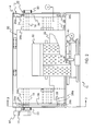
- FIG. 1 is a side elevational view of an exemplary receiver sheet supply and feeding apparatus.
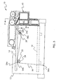
- FIG. 2 is a top plan view of the receiver sheet supply and feeding apparatus of FIG. 1, with portions removed or broken away to facilitate viewing.
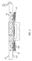
- FIG. 3 is a side elevational view of a cross-section of the receiver sheet supply and feeding apparatus taken along
lines 3--3 of FIG. 2, particularly showing the platform elevating mechanism. - FIG. 4 is an end view, on an enlarged scale and with portions removed, of a portion of the receiver sheet supply and feeding apparatus, particularly showing the feed head assembly thereof, taken along the
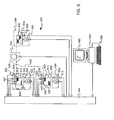
lines 4--4 of FIG. 3. - FIG. 5 is a schematic illustration of an exemplary reproduction device with two feeding apparatuses.
- FIG. 6-9 present a schematic illustrations of a different stack advancing scenes according to further aspects of the invention.
- FIG. 1 is a side elevational view of an exemplary receiver sheet supply and feeding apparatus according to one aspect of the invention. The receiver sheet supply and
feeding apparatus 10 generally includes anopen hopper 12 and anelevating platform 14 for supporting a stack of sheets. The sheet stack (not shown in Fig. 1) supported on theplatform 14 contains individual sheets suitable, for example, for serving as receiver sheets for having reproductions formed thereon in a copier or printer device. Sheets for receiving reproductions may be selected from a wide variety of materials and sizes, which altogether define the sheet attributes. For example, the sheets may be of a weight in the range of 49 grams per square meter ("gsm") to 300 gsm index, and a size in the range of 8×10 inches to 14×18 inches, or larger, or smaller, depending upon the application. - The sheet
stack supporting platform 14 is supported within thehopper 12 for substantially vertical elevational movement by a lifting mechanism ("L"). Preferably the lifting mechanism L serves to raise theplatform 14 to an elevation for maintaining the topmost sheet in the stack at a predetermined level during operation of the receiver sheet supply andfeeding apparatus 10, and to lower the platform to permit adding sheets thereto. The lifting mechanism L may include a motor ("M1"), attached to the outside of the upstanding front wall of thehopper 12. Preferably, the motor M1 rotates agear set 16 mounted on ashaft 18 extending from the upstanding rear wall of thehopper 12. A pair of sprocket mountedlifting chains 20 are respectively interconnected by gears with theshaft 18 to be moved about a closed loop path when theshaft 18 is rotated by the motor M1. As shown in FIG. 1, the sheetstack supporting platform 14 is shown in its lowest position in phantom. This most bottom position of theplatform 14 is detected with adown switch 21. - FIG. 2 is a top plan view of the receiver sheet supply and feeding
apparatus 10 of FIG. 1, with portions removed or broken away to facilitate viewing of a sheetfeed head assembly 30. The sheetfeed head assembly 30 is generally located in association with thehopper 12, so as to extend over a portion of theplatform 14 in spaced relation to asheet stack 50 supported thereon. The sheetfeed head assembly 30 includes a portedplenum 32 connected to a vacuum source V, and anair jet device 40 connected to a positive pressure air source P. Preferably, the positive pressure air jet from theair jet device 40 levitates the top several sheets in the supportedsheet stack 50, while the vacuum at theplenum 32 is effective through its ports to cause the topmost levitated sheet from thestack 50 to thereafter be acquired at theplenum 32 for separation from thesheet stack 50. Additional positive pressure air jets from theair jet device 40 helps to assure separation of subsequent sheets from the acquired topmost sheet. To further assure separation of sheets from the sheet stack, the lifting mechanism (for example, L in FIG. 1) preferably presents the top sheet a specified distance from thevacuum plenum 32. - FIG. 3 is a side elevational view of a cross-section of the exemplary receiver sheet supply and feeding
apparatus 10 taken alonglines 3--3 of FIG. 2, particularly showing theplatform 14 lifting mechanism. Each of the lifting chains have alink 22 extending throughrespective slots 12a (FIG. 1) in the front and rear upstanding walls of thehopper 12. Thelinks 22 are connected to ashaft 24a supported inbrackets 24b extending from the underside of theplatform 14.Tension cables 26 are respectively connected, at theends hopper 12. Thecables 26 are respectively threaded over their associated first pulleys 24 and undersecond pulleys 28 mounted on ashaft 28a supported in thebrackets 28b extending from the underside of theplatform 14. - In FIG. 3, the sheet
stack supporting platform 14 is shown in its most elevated position in solid lines, and in its lowest position in phantom. During the operation of the lifting mechanism L, an appropriate signal to the motor M1 causes the motor to rotate the gear set 16 (FIG. 1), such as either clockwise to lower theplatform 14 toward the lowest position or counterclockwise to raise the platform toward its most elevated position. Rotation of the gear set 16 moves the lifting chains 20 (FIG. 1) in their closed loop paths, thereby imparting vertical movement to thelinks 22. This movement, in turn, moves theshaft 24a, and thus theplatform 14, and as well as itsbrackets 24b andfirst pulleys 24. Theplatform 14 is maintained substantially level in its movement by the action of thetension cables 26, which cooperatively move thesecond pulleys 28, and thus, theshaft 28a and thebrackets 28b of theplatform 14. - FIG. 4 is an end view, on an enlarged scale and with portions removed, of a portion of the receiver sheet supply and feeding
apparatus 10, particularly showing thefeed head assembly 30 thereof, taken along thelines 4--4 of FIG. 3. Preferably, maintaining thetopmost sheet 51 at the predetermined level is accomplished by one or more sheet detecting switches 80, which controls the operation of the motor M1 for actuating the lifting mechanism L, (more described below), to raise theplatform 14 through a predetermined increment. On the other hand, lowering of theplatform 14 is usually accomplished by some externally produced signal to the motor which tells the motor to rotate until theplatform 14 reaches thedown switch 21 that signals the motor M1 to stop, often bringing theplatform 14 to its lowest position. - Of course, other precisely controllable lifting mechanisms, such as worm gears, lead screws, or scissors linkages are suitable for use in the elevation control for the sheet
stack supporting platform 14 according to these embodiments, and other suitable mechanisms without limitation. - Preferably, the
lower surface 32a of theplenum 32 of the sheetfeed head assembly 30 has a particularly configured shape, so as to provide for a specific corrugation of an acquiredsheet 51. As thetop sheets 51 in the supportedsheet stack 50 are levitated, thetopmost sheet 51 preferably contacts the outerwinged portions 32b of thesurface 32a. A minimal pressure is exerted on thesheet 51 to help in forming a controlled corrugation to thesheet 51. This establishes a consistent spacing for the center portion of thesheet 51 from the center portion of theplenum 32. As such, the access time for asheet 51 to be acquired at theplenum 32 is often repeatably consistent and readily predictable. - The interactions of the
plenum 32 and theair jet device 40 attempt to assure that control over thesheet 51, as it is acquired at theplenum 32, is not lost. Further, corrugation of thesheet 51 contorts thesheet 51 in an unnatural manner. Sincesubsequent sheets 51 are not subjected to the same forces, at the same time, as is thetopmost sheet 51, suchsubsequent sheets 51 are unable to contort in the same manner. Accordingly, thesubsequent sheets 51 are effectively separated from thetopmost sheet 51 as it is being acquired at theplenum 32. - As noted above, it is important for proper operation of the sheet supply and feeding
apparatus 10, according to this embodiment, for the level of thetopmost sheet 51 in thestack 50 supported on theplatform 14 to be maintained at a predetermined height relative to theplenum 32. The level is selected to be in a range where thetopmost sheet 51, when levitated by theair jet arrangement 42, is close enough to theplenum 32 to be readily acquired by the vacuum forces from theplenum 32, within a repeatable time frame, but yet far enough away from theplenum 32 to assure that the sheet being acquired is not pinned against theplenum 32. - Preferably, each of the
switches 80, as noted above, are designed to detect the level of thetopmost sheet 51.Such switches 80, as known in the art, could be for example, a paper guide that rides against thesheet 51 with very little downward pressure, at the highest level of acceptable corrugation, as found in US Patent US 5,823,527. Additionally, paper level actuators could be integrated into an optical switch so as to cause limited pressure on thesheet 51. Theswitches 80 can be read during the feed interval, and if necessary, will transmit a signal to the lifting mechanism L to raise theplatform 14 in one or more increments. Preferably the increments can maintain the proper sheet level. The location of theswitches 80 at the highest level of acceptable corrugation is an advantage in that each of theswitches 80 can sense the location ofsheets 51 which may be severely curled and still not pin thesheet 51 to theplenum 32. - Referring back to FIG. 1, to further assure separation of sheets from the sheet stack and the switching over to another stack, the lifting mechanism L can present the top sheet a desirable distance from the vacuum plenum, in response to a second signal that originates from a secondary source other than the
switches 80, such as by a microprocessor executing source code, or hardware logic. - FIG. 5 is a scheme illustrating an
exemplary reproduction device 500 with two feedingapparatuses apparatus platform stack platform stepper motor Sheets stack feed head assembly level sensors sensor sheet platform platform down switches sheets optical edge sensor 534, 536 is arranged in thetransport path sheets printing unit 542. After printing thesheets piling apparatus 544. The piling apparatus contains a platform 546 to discard thesheets stepper motor 550 whereby the bottom position is detected with adown switch 552. - As shown in Fig. 5 all active and sensor elements are connected to a control system 554 for the
reproduction device 500. To input, process and display data the control system 554 is connected to acomputer system 556 with akeyboard 558 and amonitor 560. Preferably, software for controlling feeding, of types known in the art, is modified in accordance with the present invention to provide the functionality described herein. - With Fig. 6-9 it will be described below how the stack-advancing may be performed according to various further aspects of the invention. Referring now to Figure 6 (with reference to Figure 5), a first procedure is presented wherein a number of steps needed to advance the
stacks printing unit 500 is manufactured and the feedingapparatuses computer system 556, first a total possible displacement count is initialized to a nominal value NT. The initialized value NT is stored in Non-Volatile Memory ("NVM", for example battery-backed memory, flash memory, etc.), also referred to herein as "persistent memory", within the control system 554. Next acomplete stack stepper motor sheets head assembly motor edge sensor 534, 536. This procedure goes on until the paper outsensor platform - In Fig. 6 there is shown a
platform platform down switch sheets empty platform level sensor - The new total possible displacement count NT may be checked to determine whether it lies in a predetermined range of values. If not an error message may be displayed on the
monitor 560. In this case a service person could do further checking. - Referring now to Figures 5 and 6, the number of steps needed for the stepper motor 514 (Figure 5) to advance the
stack 510 for feeding K sheets may be determined, wherein K is the number ofsheets 518 that should remain in thestack 510 before the scheduling of future feeding goes to theother stack 512 in a continuous mode. For example, K may be the maximum number of sheets that can potentially be scheduled in advance. This paper low displacement procedure is automatically realized by recording the number of steps NK required to feed K sheets at some point during the reproduction process before only K sheets are left in the stack 510,512. - A paper-low value, NL, may be determined by subtracting NK from NT. NL may be used to signal a user that paper is almost out in a particular hopper, or it may be used to initiate transfer to another paper supply when paper is feeding in continuous mode. Preferably, K corresponds to a number of sheet feeds already fed from a corresponding supply before NL is reached. This value NL is also stored in the memory, preferably volatile Random Access Memory (RAM) rather than NVM.
- The system may be initialized with a value NL that represents a nominal paper-low value. For example, if it is determined that an access to the
hopper 12 ofapparatus - With the
motor 514 the stack is advanced up to the level of the feed-head assembly 522, as shown in Figure 7. The arrival at the feed-head assembly is confirmed by thelevel sensor 526. After thelevel sensor 526 is activated the current step count is recorded as No in the memory. K sheets are fed, and the corresponding step count N1 is recorded. The number of step counts corresponding to K sheets is NK = N1 - N0. Finally a new paper low nominal value NL may be calculated as the difference between the total possible displacement NT and NK, NL = NT - NK. Thestack 510 has now the position shown in Fig. 8. - After determining the paper low value, NL, feeding may continue until the actual step count reaches NL. The
platform 506 has then the level shown in Fig. 9. The scheduling fromstack 510 will be stopped and is continued with feedingapparatus 504 activated with the control system 554. The feeding out ofapparatus 504 is done in the same way as described with feedingapparatus 502. - While the switching over from one
feeding apparatus 502 to thenext feeding apparatus 504 has been described with the remaining sheet number K, it should be clear that the switching over could be delayed by feeding J additional sheets with thefeeding apparatus 502. For example, after paper low NL is reached, allow scheduling of J additional feeds in a manner to insure that not more than K feeds occur from that point prior to switching the supplies. I.e., if six additional feeds (J) are scheduled when paper low NL is reached, allow K-6 (k-J) more feeds to be scheduled prior to switching to feedingapparatus 504. - The present embodiments described herein, provide the ability to more effectively and reliably control stack-advancing in a reproduction device, by automatically calibrating the counts for the stepper motors M1, 514, 516. Although described in the setting of a reproduction device utilizing a top
feed vacuum feeder - The disclosed method provides a number of advantages and applications. Utilizing the disclosed embodiments, the present invention allows better control over the number of sheets remaining during a continuous mode swap even if the sheet attributes and the mechanical tolerances change or vary from stack to stack.
- It should also be understood that the programs, processes, methods and systems described herein are not related or limited to any particular type of hardware, such as TTL logic or computer software, or both. Various types of general purpose or specialized processors, such as micro-controllers may be used with or perform operations in accordance with the teachings described herein.
- In view of the wide variety of embodiments to which the principles of the present invention can be applied, it should be understood that the illustrated embodiments are exemplary only, and should not be taken as limiting the scope of the present invention. For example, more or fewer elements may be used in the drawings and signals may include analog, digital, or both. While various elements of the preferred embodiments have been described as being implemented in hardware, in other embodiments in software implementations may alternatively be used, and vice-versa. For example, the said stepper motor, could be any type of motor with feedback for platform movement such as an encoder or a potentiometer.
- The present embodiments described herein, provide the ability to more effectively control a paper stack in a reproduction device. The system and method have been implemented in a reproduction device utilizing a top feed vacuum feeder. However, it should be understood that the present embodiments can be implemented in a reproduction device that utilizes other types of feeders, including variations of the vacuum feeder or a friction feeder. Thus, the exemplary embodiments disclose a system and method that can be utilized to increase the efficiency for any type of reproduction machine.
-
- 10
- feeding apparatus
- 12
- open hopper
- 12a
- slot
- 14
- elevating platform
- 16
- gear set
- 18
- shaft
- 20
- lifting chains
- 21
- down switch
- 22
- link
- 24
- first pulley
- 24a
- shaft
- 24b
- bracket
- 26
- cable
- 26a, 26b
- end
- 28
- second pulley
- 28a
- shaft
- 28b
- bracket
- 30
- sheet feed head assembly
- 32
- plenum
- 32a
- surface
- 32b
- outer winged portion
- 40
- air jet device
- 42
- air jet arrangement
- 50
- sheet stack
- 80
- switch
- L
- lifting mechanism
- M1
- motor
- 500
- reproduction device
- 502, 504
- feeding apparatus
- 506, 508
- platform
- 51
- sheet
- 510, 512
- supporting stack
- 514, 516
- elevating stepper motor
- 518, 520
- Sheets
- 522, 524
- feed head assembly.
- 526, 528
- level sensor
- 527, 529
- paper out sensor
- 530, 532
- down switche
- 534, 536
- optical edge sensor
- 538, 540
- transport path
- 542
- printing unit
- 544
- piling apparatus
- 546
- platform
- 548
- stack
- 550
- stepper motor
- 552
- down switch
- 554
- control system
- 556
- computer system
- 558
- keyboard
- 560
- monitor
- P
- positive pressure air source
- V
- vacuum source
Claims (15)
- A method for controlling sheet stack advancing,
comprising:determining a distance of a platform relative to a feedhead corresponding to a predetermined number of sheets to be left in a sheet supply, said sheets resting upon said platform;switching to another sheet supply when said platform is said distance from said feedhead thereby leaving said predetermined number of sheets in said sheet supply, said predetermined number remaining unchanged regardless of a sheet thickness. - A method for controlling sheet stack advancing,
comprising:determining a sheet thickness by measuring a displacement of a platform corresponding to a known number of sheet feeds by said feedhead, said sheets resting upon said platform;determining a distance of said platform relative to a feedhead corresponding to a predetermined number of sheets having said sheet thickness to be left in a sheet supply;switching scheduling of future feeds to another sheet supply when said platform is said distance from said feedhead. - The method of one of the claims 1 to 2,
further comprising driving said platform with a stepper motor, and expressing said distance as stepper motor counts. - The method of one of the claims 1 to 3,
further comprising determining said distance prior to said platform being at said distance relative to said feedhead. - The method of one of the claims 1 to 4,
further comprising storing said distance in memory. - A method for controlling sheet stack advancing, comprising:determining a maximum travel of a platform and storing it in a memory, said sheet stack resting upon said platform;advancing said platform with a motor from a bottom-most to a top-most height position and performing sheet separating and feeding;determining a current platform travel before every feed;saving said current platform travel in said memory and comparing said current platform travel with a nominal platform travel, and updating said maximum travel in memory each time said platform is completely emptied of sheets.
- The method of claim 6, further comprising generating an error signal if a difference between said current platform travel and said nominal platform travel is greater than a predetermined value.
- A method for controlling stack advancing in a reproduction apparatus, comprising:determining maximum platform displacement, NT, and storing it in memory, a stack of sheets resting on said platform;advancing said platform and performing sheet separating and feeding for K sheets;recording a current platform displacement, NK, that occurred during feeding said K sheets; and,calculating a paper low displacement NL = NT - NK and storing NL in memory.
- A method for controlling stack-advancing in a reproduction apparatus, comprising:driving a platform in steps with a lifting motor and performing sheet separating and feeding;initializing a paper-low displacement, NL, of said platform to a nominal number of said steps and storing it in memory;determining a number of steps of said lifting motor to achieve movement from a bottom position to a top position of said platform, NT, and storing it in a memory;separating and feeding K sheets and recording in memory an actual number of said steps corresponding to feeding said K sheets, NK;replacing said nominal number of steps with NT-NK in memory.
- The method of claim 9,
further comprising initializing NL to a nominal value and storing it in memory. - The method of one of the claims 8 to 10,
wherein reaching NL initiates switching over to feed from another stack loaded with the same sheet attributes. - The method of one of the claims 8 to 11,
comprising initializing NL if at least one of the following cases: in response to a renewal of the stack; in response to a change of sheet attributes. - The method of one of the claims 8 to 12, further comprising initializing NL to a nominal value, storing it in memory, and replacing it with a determined NL for that stack.
- The method of one of the claims 8 to 13, further comprising driving said platform with a stepper motor, and expressing said displacement as stepper motor counts.
- A method for controlling sheet stack advancing,
comprising:determining a distance of a platform relative to a feedhead corresponding to a predetermined number of sheets K to be left in a sheet supply, said sheets resting upon said platform;determining a number of feeds J already scheduled from said sheets when said platform is said distance from said feedhead;scheduling up to K-J more feeds from said sheets, andswitching further scheduling to another sheet supply.
Applications Claiming Priority (2)
| Application Number | Priority Date | Filing Date | Title |
|---|---|---|---|
| US41389802P | 2002-09-26 | 2002-09-26 | |
| US413898P | 2002-09-26 |
Publications (2)
| Publication Number | Publication Date |
|---|---|
| EP1403200A2 true EP1403200A2 (en) | 2004-03-31 |
| EP1403200A3 EP1403200A3 (en) | 2005-04-06 |
Family
ID=31978788
Family Applications (1)
| Application Number | Title | Priority Date | Filing Date |
|---|---|---|---|
| EP03021117A Withdrawn EP1403200A3 (en) | 2002-09-26 | 2003-09-19 | Method for controlling stack-advancing in a reproduction apparatus |
Country Status (2)
| Country | Link |
|---|---|
| US (3) | US20040061280A1 (en) |
| EP (1) | EP1403200A3 (en) |
Cited By (1)
| Publication number | Priority date | Publication date | Assignee | Title |
|---|---|---|---|---|
| EP2330064A3 (en) * | 2009-12-04 | 2013-07-10 | Ricoh Company Ltd. | Sheet conveying device and image forming apparatus incorporating same |
Families Citing this family (13)
| Publication number | Priority date | Publication date | Assignee | Title |
|---|---|---|---|---|
| US7048273B2 (en) * | 2002-02-28 | 2006-05-23 | Bowe Bell + Howell Company | System and method for monitoring grouped resources |
| EP1403200A3 (en) * | 2002-09-26 | 2005-04-06 | Eastman Kodak Company | Method for controlling stack-advancing in a reproduction apparatus |
| JP4323993B2 (en) * | 2004-03-22 | 2009-09-02 | キヤノン株式会社 | Sheet feeding device, sheet feeding method, and control program |
| JP4979515B2 (en) * | 2007-08-28 | 2012-07-18 | キヤノン株式会社 | Sheet feeding apparatus and image forming apparatus |
| JP5116544B2 (en) * | 2008-04-14 | 2013-01-09 | キヤノン株式会社 | Image forming apparatus |
| JP5494938B2 (en) * | 2009-03-05 | 2014-05-21 | コニカミノルタ株式会社 | Paper feeding device and image forming apparatus |
| US8061706B2 (en) * | 2009-04-24 | 2011-11-22 | Xerox Corporation | Method and apparatus for adjusting the height of a media stack in an image production device |
| US8231124B2 (en) | 2009-06-23 | 2012-07-31 | Kyocera Mita Corporation | Paper feeding device and image forming apparatus |
| GB201001814D0 (en) * | 2010-02-04 | 2010-03-24 | Vivid Laminating Technologies | Feed mechanism for laminating machine |
| JP5135390B2 (en) * | 2010-06-30 | 2013-02-06 | 京セラドキュメントソリューションズ株式会社 | Paper remaining amount detection device, image forming device |
| US8820739B1 (en) * | 2013-04-04 | 2014-09-02 | Xerox Corporation | Method for optimizing feeder module feeder tray capacity |
| JP2015124028A (en) * | 2013-12-25 | 2015-07-06 | 株式会社沖データ | Image formation device |
| JP6930158B2 (en) * | 2017-03-17 | 2021-09-01 | コニカミノルタ株式会社 | Image forming apparatus, print control program and print control method |
Family Cites Families (22)
| Publication number | Priority date | Publication date | Assignee | Title |
|---|---|---|---|---|
| JPS54126364A (en) * | 1978-03-25 | 1979-10-01 | Minolta Camera Kk | Paper feeder |
| US4535463A (en) * | 1981-10-13 | 1985-08-13 | Minolta Camera Co., Ltd. | Apparatus for detecting number of remaining sheets |
| JPS60188244A (en) * | 1984-03-02 | 1985-09-25 | Minolta Camera Co Ltd | Paper feed conrol device |
| JPS60188245A (en) | 1984-03-06 | 1985-09-25 | Minolta Camera Co Ltd | Paper feed control device |
| US5028041A (en) * | 1984-10-26 | 1991-07-02 | Canon Kabushiki Kaisha | Image forming apparatus with sheet feeder |
| DE3618728A1 (en) * | 1985-06-04 | 1986-12-04 | Ricoh Co., Ltd., Tokio/Tokyo | CONTROL DEVICE FOR PAPER FEEDING IN A COPIER |
| US4835573A (en) * | 1988-04-29 | 1989-05-30 | International Business Machines Corporation | Machine control system utilizing paper parameter measurements |
| JP2938583B2 (en) * | 1989-12-22 | 1999-08-23 | 株式会社リコー | Paper feeder |
| EP0531816B1 (en) * | 1991-08-28 | 1995-11-02 | Mita Industrial Co. Ltd. | A sheet feeder |
| US5344133A (en) * | 1993-02-25 | 1994-09-06 | Eastman Kodak Company | Vacuum belt feeder having a positive air pressure separator and method of using a vacuum belt feeder |
| US5472183A (en) * | 1994-03-17 | 1995-12-05 | Nisca Corporation | Sheet feeding device with multiple sheet stackers |
| US5823527A (en) * | 1995-12-29 | 1998-10-20 | Eastman Kodak Company | Control for a sheet stack supporting platform |
| JP3314329B2 (en) * | 1996-04-25 | 2002-08-12 | ミノルタ株式会社 | Automatic paper feeder |
| DE69827091T2 (en) * | 1997-08-27 | 2006-03-09 | Sharp K.K. | A sheet feeding method for an image forming apparatus wherein the sheet transport path of one sheet cassette serves as part of the sheet transport path of another sheet cassette |
| US5971357A (en) * | 1997-11-14 | 1999-10-26 | Wolfe Tory Medical, Inc. | Fluid delivery valve |
| US6485013B2 (en) * | 2000-12-04 | 2002-11-26 | Hewlett-Packard Company | Method and apparatus for detecting media level in a cassette |
| US6698747B2 (en) * | 2001-02-06 | 2004-03-02 | Heidelberger Druckmaschinen Ag | Method and system for providing sheet stack level control |
| US20030015836A1 (en) * | 2001-07-19 | 2003-01-23 | Eastman Kodak Company | Capacity control system for a paper supply elevator |
| US6685181B2 (en) * | 2002-02-15 | 2004-02-03 | Gbr Systems Corporation | Paper dispensing mechanism |
| JP3959328B2 (en) * | 2002-03-20 | 2007-08-15 | 株式会社東芝 | Paper sheet take-out device and paper sheet take-out method |
| US20070096387A1 (en) * | 2002-09-26 | 2007-05-03 | Sciurba Thomas K | Method for controlling stack-advancing in a reproduction apparatus |
| EP1403200A3 (en) * | 2002-09-26 | 2005-04-06 | Eastman Kodak Company | Method for controlling stack-advancing in a reproduction apparatus |
-
2003
- 2003-09-19 EP EP03021117A patent/EP1403200A3/en not_active Withdrawn
- 2003-09-23 US US10/668,417 patent/US20040061280A1/en not_active Abandoned
-
2009
- 2009-02-26 US US12/393,149 patent/US7815182B2/en not_active Expired - Fee Related
-
2010
- 2010-09-10 US US12/879,059 patent/US20100327514A1/en not_active Abandoned
Cited By (1)
| Publication number | Priority date | Publication date | Assignee | Title |
|---|---|---|---|---|
| EP2330064A3 (en) * | 2009-12-04 | 2013-07-10 | Ricoh Company Ltd. | Sheet conveying device and image forming apparatus incorporating same |
Also Published As
| Publication number | Publication date |
|---|---|
| EP1403200A3 (en) | 2005-04-06 |
| US7815182B2 (en) | 2010-10-19 |
| US20090166950A1 (en) | 2009-07-02 |
| US20040061280A1 (en) | 2004-04-01 |
| US20100327514A1 (en) | 2010-12-30 |
Similar Documents
| Publication | Publication Date | Title |
|---|---|---|
| US7815182B2 (en) | Method for controlling stack-advancing in a reproduction apparatus | |
| EP0340135B1 (en) | Machine control system utilizing paper parameter measurements | |
| EP1092659B1 (en) | Method of feeding sheets | |
| JP4979515B2 (en) | Sheet feeding apparatus and image forming apparatus | |
| US8079585B2 (en) | Sheet feeding device and image forming apparatus | |
| JPH09235033A (en) | Paper feeding device | |
| US6908082B2 (en) | Method and system for providing sheet stack level control | |
| US7775519B2 (en) | Large capacity sheet feeding apparatus having an intermediate conveying device | |
| US20070096387A1 (en) | Method for controlling stack-advancing in a reproduction apparatus | |
| JP2002104679A (en) | Sheet separation device and sheet feeding device | |
| JP7417195B2 (en) | Feeding device and image forming device | |
| US20090001646A1 (en) | Image forming apparatus | |
| JP2010100426A (en) | Sheet residual quantity detection device and image forming device | |
| US7887045B2 (en) | Method for dynamically lifting elevator platform of media input tray during ongoing media process | |
| JP2000198557A (en) | Air suction-type paper feeding device | |
| CN1176892A (en) | Paper transporting system and method of ink-jet printer for preventing paper from being jammed and folded. | |
| JP7512666B2 (en) | Paper feeder and image forming apparatus | |
| JP3358207B2 (en) | Double feed detection device | |
| JP2004043186A (en) | Air suction type paper feeding transport device | |
| JP2007269481A (en) | Sheet material feeding apparatus and image forming apparatus | |
| JP3295971B2 (en) | Paper feeder | |
| JPH0891593A (en) | Paper feed control method in mass paper feeder | |
| KR100419218B1 (en) | Paper stacking apparatus for printer | |
| JP2006143346A (en) | Paper feeding device for image forming device | |
| JPH042495B2 (en) |
Legal Events
| Date | Code | Title | Description |
|---|---|---|---|
| PUAI | Public reference made under article 153(3) epc to a published international application that has entered the european phase |
Free format text: ORIGINAL CODE: 0009012 |
|
| AK | Designated contracting states |
Kind code of ref document: A2 Designated state(s): AT BE BG CH CY CZ DE DK EE ES FI FR GB GR HU IE IT LI LU MC NL PT RO SE SI SK TR |
|
| AX | Request for extension of the european patent |
Extension state: AL LT LV MK |
|
| RAP1 | Party data changed (applicant data changed or rights of an application transferred) |
Owner name: EASTMAN KODAK COMPANY |
|
| PUAL | Search report despatched |
Free format text: ORIGINAL CODE: 0009013 |
|
| AK | Designated contracting states |
Kind code of ref document: A3 Designated state(s): AT BE BG CH CY CZ DE DK EE ES FI FR GB GR HU IE IT LI LU MC NL PT RO SE SI SK TR |
|
| AX | Request for extension of the european patent |
Extension state: AL LT LV MK |
|
| AKX | Designation fees paid | ||
| REG | Reference to a national code |
Ref country code: DE Ref legal event code: 8566 |
|
| STAA | Information on the status of an ep patent application or granted ep patent |
Free format text: STATUS: THE APPLICATION IS DEEMED TO BE WITHDRAWN |
|
| 18D | Application deemed to be withdrawn |
Effective date: 20051007 |