EP1403189B1 - Bottle container - Google Patents
Bottle container Download PDFInfo
- Publication number
- EP1403189B1 EP1403189B1 EP20020380237 EP02380237A EP1403189B1 EP 1403189 B1 EP1403189 B1 EP 1403189B1 EP 20020380237 EP20020380237 EP 20020380237 EP 02380237 A EP02380237 A EP 02380237A EP 1403189 B1 EP1403189 B1 EP 1403189B1
- Authority
- EP
- European Patent Office
- Prior art keywords
- container
- lid
- runners
- bars
- pair
- Prior art date
- Legal status (The legal status is an assumption and is not a legal conclusion. Google has not performed a legal analysis and makes no representation as to the accuracy of the status listed.)
- Expired - Lifetime
Links
- 230000000903 blocking effect Effects 0.000 claims description 7
- 230000003319 supportive effect Effects 0.000 claims 1
- 239000002184 metal Substances 0.000 description 4
- 210000003739 neck Anatomy 0.000 description 3
- 230000000694 effects Effects 0.000 description 2
- 230000004048 modification Effects 0.000 description 2
- 238000012986 modification Methods 0.000 description 2
- 238000006073 displacement reaction Methods 0.000 description 1
Images


Classifications
-
- B—PERFORMING OPERATIONS; TRANSPORTING
- B65—CONVEYING; PACKING; STORING; HANDLING THIN OR FILAMENTARY MATERIAL
- B65D—CONTAINERS FOR STORAGE OR TRANSPORT OF ARTICLES OR MATERIALS, e.g. BAGS, BARRELS, BOTTLES, BOXES, CANS, CARTONS, CRATES, DRUMS, JARS, TANKS, HOPPERS, FORWARDING CONTAINERS; ACCESSORIES, CLOSURES, OR FITTINGS THEREFOR; PACKAGING ELEMENTS; PACKAGES
- B65D19/00—Pallets or like platforms, with or without side walls, for supporting loads to be lifted or lowered
- B65D19/02—Rigid pallets with side walls, e.g. box pallets
- B65D19/06—Rigid pallets with side walls, e.g. box pallets with bodies formed by uniting or interconnecting two or more components
- B65D19/08—Rigid pallets with side walls, e.g. box pallets with bodies formed by uniting or interconnecting two or more components made wholly or mainly of metal
- B65D19/10—Rigid pallets with side walls, e.g. box pallets with bodies formed by uniting or interconnecting two or more components made wholly or mainly of metal of skeleton construction, e.g. made of wire
-
- B—PERFORMING OPERATIONS; TRANSPORTING
- B65—CONVEYING; PACKING; STORING; HANDLING THIN OR FILAMENTARY MATERIAL
- B65D—CONTAINERS FOR STORAGE OR TRANSPORT OF ARTICLES OR MATERIALS, e.g. BAGS, BARRELS, BOTTLES, BOXES, CANS, CARTONS, CRATES, DRUMS, JARS, TANKS, HOPPERS, FORWARDING CONTAINERS; ACCESSORIES, CLOSURES, OR FITTINGS THEREFOR; PACKAGING ELEMENTS; PACKAGES
- B65D2519/00—Pallets or like platforms, with or without side walls, for supporting loads to be lifted or lowered
- B65D2519/00004—Details relating to pallets
- B65D2519/00009—Materials
- B65D2519/00049—Materials for the base surface
- B65D2519/00059—Metal
-
- B—PERFORMING OPERATIONS; TRANSPORTING
- B65—CONVEYING; PACKING; STORING; HANDLING THIN OR FILAMENTARY MATERIAL
- B65D—CONTAINERS FOR STORAGE OR TRANSPORT OF ARTICLES OR MATERIALS, e.g. BAGS, BARRELS, BOTTLES, BOXES, CANS, CARTONS, CRATES, DRUMS, JARS, TANKS, HOPPERS, FORWARDING CONTAINERS; ACCESSORIES, CLOSURES, OR FITTINGS THEREFOR; PACKAGING ELEMENTS; PACKAGES
- B65D2519/00—Pallets or like platforms, with or without side walls, for supporting loads to be lifted or lowered
- B65D2519/00004—Details relating to pallets
- B65D2519/00009—Materials
- B65D2519/00119—Materials for the construction of the reinforcements
- B65D2519/00129—Metal
-
- B—PERFORMING OPERATIONS; TRANSPORTING
- B65—CONVEYING; PACKING; STORING; HANDLING THIN OR FILAMENTARY MATERIAL
- B65D—CONTAINERS FOR STORAGE OR TRANSPORT OF ARTICLES OR MATERIALS, e.g. BAGS, BARRELS, BOTTLES, BOXES, CANS, CARTONS, CRATES, DRUMS, JARS, TANKS, HOPPERS, FORWARDING CONTAINERS; ACCESSORIES, CLOSURES, OR FITTINGS THEREFOR; PACKAGING ELEMENTS; PACKAGES
- B65D2519/00—Pallets or like platforms, with or without side walls, for supporting loads to be lifted or lowered
- B65D2519/00004—Details relating to pallets
- B65D2519/00009—Materials
- B65D2519/00154—Materials for the side walls
- B65D2519/00164—Metal
-
- B—PERFORMING OPERATIONS; TRANSPORTING
- B65—CONVEYING; PACKING; STORING; HANDLING THIN OR FILAMENTARY MATERIAL
- B65D—CONTAINERS FOR STORAGE OR TRANSPORT OF ARTICLES OR MATERIALS, e.g. BAGS, BARRELS, BOTTLES, BOXES, CANS, CARTONS, CRATES, DRUMS, JARS, TANKS, HOPPERS, FORWARDING CONTAINERS; ACCESSORIES, CLOSURES, OR FITTINGS THEREFOR; PACKAGING ELEMENTS; PACKAGES
- B65D2519/00—Pallets or like platforms, with or without side walls, for supporting loads to be lifted or lowered
- B65D2519/00004—Details relating to pallets
- B65D2519/00009—Materials
- B65D2519/00189—Materials for the lid or cover
- B65D2519/00199—Metal
-
- B—PERFORMING OPERATIONS; TRANSPORTING
- B65—CONVEYING; PACKING; STORING; HANDLING THIN OR FILAMENTARY MATERIAL
- B65D—CONTAINERS FOR STORAGE OR TRANSPORT OF ARTICLES OR MATERIALS, e.g. BAGS, BARRELS, BOTTLES, BOXES, CANS, CARTONS, CRATES, DRUMS, JARS, TANKS, HOPPERS, FORWARDING CONTAINERS; ACCESSORIES, CLOSURES, OR FITTINGS THEREFOR; PACKAGING ELEMENTS; PACKAGES
- B65D2519/00—Pallets or like platforms, with or without side walls, for supporting loads to be lifted or lowered
- B65D2519/00004—Details relating to pallets
- B65D2519/00009—Materials
- B65D2519/00223—Materials for the corner elements or corner frames
- B65D2519/00233—Metal
-
- B—PERFORMING OPERATIONS; TRANSPORTING
- B65—CONVEYING; PACKING; STORING; HANDLING THIN OR FILAMENTARY MATERIAL
- B65D—CONTAINERS FOR STORAGE OR TRANSPORT OF ARTICLES OR MATERIALS, e.g. BAGS, BARRELS, BOTTLES, BOXES, CANS, CARTONS, CRATES, DRUMS, JARS, TANKS, HOPPERS, FORWARDING CONTAINERS; ACCESSORIES, CLOSURES, OR FITTINGS THEREFOR; PACKAGING ELEMENTS; PACKAGES
- B65D2519/00—Pallets or like platforms, with or without side walls, for supporting loads to be lifted or lowered
- B65D2519/00004—Details relating to pallets
- B65D2519/00258—Overall construction
- B65D2519/00313—Overall construction of the base surface
- B65D2519/00328—Overall construction of the base surface shape of the contact surface of the base
- B65D2519/00333—Overall construction of the base surface shape of the contact surface of the base contact surface having a stringer-like shape
-
- B—PERFORMING OPERATIONS; TRANSPORTING
- B65—CONVEYING; PACKING; STORING; HANDLING THIN OR FILAMENTARY MATERIAL
- B65D—CONTAINERS FOR STORAGE OR TRANSPORT OF ARTICLES OR MATERIALS, e.g. BAGS, BARRELS, BOTTLES, BOXES, CANS, CARTONS, CRATES, DRUMS, JARS, TANKS, HOPPERS, FORWARDING CONTAINERS; ACCESSORIES, CLOSURES, OR FITTINGS THEREFOR; PACKAGING ELEMENTS; PACKAGES
- B65D2519/00—Pallets or like platforms, with or without side walls, for supporting loads to be lifted or lowered
- B65D2519/00004—Details relating to pallets
- B65D2519/00258—Overall construction
- B65D2519/00398—Overall construction reinforcements
- B65D2519/00432—Non-integral, e.g. inserts
- B65D2519/00452—Non-integral, e.g. inserts on the walls
-
- B—PERFORMING OPERATIONS; TRANSPORTING
- B65—CONVEYING; PACKING; STORING; HANDLING THIN OR FILAMENTARY MATERIAL
- B65D—CONTAINERS FOR STORAGE OR TRANSPORT OF ARTICLES OR MATERIALS, e.g. BAGS, BARRELS, BOTTLES, BOXES, CANS, CARTONS, CRATES, DRUMS, JARS, TANKS, HOPPERS, FORWARDING CONTAINERS; ACCESSORIES, CLOSURES, OR FITTINGS THEREFOR; PACKAGING ELEMENTS; PACKAGES
- B65D2519/00—Pallets or like platforms, with or without side walls, for supporting loads to be lifted or lowered
- B65D2519/00004—Details relating to pallets
- B65D2519/00258—Overall construction
- B65D2519/00398—Overall construction reinforcements
- B65D2519/00432—Non-integral, e.g. inserts
- B65D2519/00457—Non-integral, e.g. inserts on the lid or cover
-
- B—PERFORMING OPERATIONS; TRANSPORTING
- B65—CONVEYING; PACKING; STORING; HANDLING THIN OR FILAMENTARY MATERIAL
- B65D—CONTAINERS FOR STORAGE OR TRANSPORT OF ARTICLES OR MATERIALS, e.g. BAGS, BARRELS, BOTTLES, BOXES, CANS, CARTONS, CRATES, DRUMS, JARS, TANKS, HOPPERS, FORWARDING CONTAINERS; ACCESSORIES, CLOSURES, OR FITTINGS THEREFOR; PACKAGING ELEMENTS; PACKAGES
- B65D2519/00—Pallets or like platforms, with or without side walls, for supporting loads to be lifted or lowered
- B65D2519/00004—Details relating to pallets
- B65D2519/00258—Overall construction
- B65D2519/00492—Overall construction of the side walls
- B65D2519/00512—Overall construction of the side walls skeleton type
-
- B—PERFORMING OPERATIONS; TRANSPORTING
- B65—CONVEYING; PACKING; STORING; HANDLING THIN OR FILAMENTARY MATERIAL
- B65D—CONTAINERS FOR STORAGE OR TRANSPORT OF ARTICLES OR MATERIALS, e.g. BAGS, BARRELS, BOTTLES, BOXES, CANS, CARTONS, CRATES, DRUMS, JARS, TANKS, HOPPERS, FORWARDING CONTAINERS; ACCESSORIES, CLOSURES, OR FITTINGS THEREFOR; PACKAGING ELEMENTS; PACKAGES
- B65D2519/00—Pallets or like platforms, with or without side walls, for supporting loads to be lifted or lowered
- B65D2519/00004—Details relating to pallets
- B65D2519/00547—Connections
- B65D2519/00577—Connections structures connecting side walls, including corner posts, to each other
- B65D2519/00616—Connections structures connecting side walls, including corner posts, to each other structures not intended to be disassembled
- B65D2519/00626—Connections structures connecting side walls, including corner posts, to each other structures not intended to be disassembled sidewalls connected via corner posts
-
- B—PERFORMING OPERATIONS; TRANSPORTING
- B65—CONVEYING; PACKING; STORING; HANDLING THIN OR FILAMENTARY MATERIAL
- B65D—CONTAINERS FOR STORAGE OR TRANSPORT OF ARTICLES OR MATERIALS, e.g. BAGS, BARRELS, BOTTLES, BOXES, CANS, CARTONS, CRATES, DRUMS, JARS, TANKS, HOPPERS, FORWARDING CONTAINERS; ACCESSORIES, CLOSURES, OR FITTINGS THEREFOR; PACKAGING ELEMENTS; PACKAGES
- B65D2519/00—Pallets or like platforms, with or without side walls, for supporting loads to be lifted or lowered
- B65D2519/00004—Details relating to pallets
- B65D2519/00547—Connections
- B65D2519/00671—Connections structures connecting corner posts to the pallet
- B65D2519/00701—Structures not intended to be disassembled
-
- B—PERFORMING OPERATIONS; TRANSPORTING
- B65—CONVEYING; PACKING; STORING; HANDLING THIN OR FILAMENTARY MATERIAL
- B65D—CONTAINERS FOR STORAGE OR TRANSPORT OF ARTICLES OR MATERIALS, e.g. BAGS, BARRELS, BOTTLES, BOXES, CANS, CARTONS, CRATES, DRUMS, JARS, TANKS, HOPPERS, FORWARDING CONTAINERS; ACCESSORIES, CLOSURES, OR FITTINGS THEREFOR; PACKAGING ELEMENTS; PACKAGES
- B65D2519/00—Pallets or like platforms, with or without side walls, for supporting loads to be lifted or lowered
- B65D2519/00004—Details relating to pallets
- B65D2519/00547—Connections
- B65D2519/00706—Connections structures connecting the lid or cover to the side walls or corner posts
- B65D2519/00711—Connections structures connecting the lid or cover to the side walls or corner posts removable lid or covers
-
- B—PERFORMING OPERATIONS; TRANSPORTING
- B65—CONVEYING; PACKING; STORING; HANDLING THIN OR FILAMENTARY MATERIAL
- B65D—CONTAINERS FOR STORAGE OR TRANSPORT OF ARTICLES OR MATERIALS, e.g. BAGS, BARRELS, BOTTLES, BOXES, CANS, CARTONS, CRATES, DRUMS, JARS, TANKS, HOPPERS, FORWARDING CONTAINERS; ACCESSORIES, CLOSURES, OR FITTINGS THEREFOR; PACKAGING ELEMENTS; PACKAGES
- B65D2519/00—Pallets or like platforms, with or without side walls, for supporting loads to be lifted or lowered
- B65D2519/00004—Details relating to pallets
- B65D2519/00736—Details
- B65D2519/00805—Means for facilitating the removal of the load
-
- B—PERFORMING OPERATIONS; TRANSPORTING
- B65—CONVEYING; PACKING; STORING; HANDLING THIN OR FILAMENTARY MATERIAL
- B65D—CONTAINERS FOR STORAGE OR TRANSPORT OF ARTICLES OR MATERIALS, e.g. BAGS, BARRELS, BOTTLES, BOXES, CANS, CARTONS, CRATES, DRUMS, JARS, TANKS, HOPPERS, FORWARDING CONTAINERS; ACCESSORIES, CLOSURES, OR FITTINGS THEREFOR; PACKAGING ELEMENTS; PACKAGES
- B65D2519/00—Pallets or like platforms, with or without side walls, for supporting loads to be lifted or lowered
- B65D2519/00004—Details relating to pallets
- B65D2519/00736—Details
- B65D2519/0098—Dismountable elements
- B65D2519/00995—Dismountable elements detachable elements of the side wall, i.e. not the whole wall
Definitions
- the present invention refers to a bottle container, of the type formed by a prismatic-rectangular metal box, with a rigid angular frame, onto which metal grids are attached, thereby forming the faces of the container, so that the latter, when conveniently loaded with bottles, is liable to adopt two working positions in which the bottles are laid horizontally and vertically, whereas there are supports for both of these positions, allowing the containers to be placed on the floor or stacked together.
- the object of the invention is to improve the structure of this type of containers, with a view to avoiding handling problems that occur when that handling is carried out by robots.
- the base of the container and also on one of its lateral faces, the one opposite the door there are supporting runners which allow to slide and move the container on the floor or on conveyor platforms, so that no matter which position the container adopts, i.e. whether the bottles are horizontal or vertical, it is always supported by the aforementioned runners, which also create a convenient distance between the container and the floor, allowing to introduce the fork of a lift truck.
- the bottle container proposed by this invention is based on the aforementioned utility model and includes a series of improvements that fully solve the aforementioned problems. This is achieved by means of a bottle container according to appended claim 1.
- diagonal stiffening bars are placed on the side wall of the container opposite the door, on which in any case the arms or catches of the fork lift are to rest, whether they are short or long, so that it is the stiffening bars that bear the weight of the container's load and undesirable deformation of the metal grid, which constitutes the closure of this face is avoided.
- the bars that receive the shanks of the afore-mentioned bolts should include, as well as at least one vertical line of holes to selectively receive the bolts, a middle line of transversal slots intended to selectively receive the bars that slide over the lid itself, more specifically, where each of them will be guided between a pair of bars, at intervals equal to those of the bars, forming a guide that is closed at the bottom by the grid of the lid itself and on the top with the collaboration of a pair of transversal rounds, which also act as slide limit stops for the bars, which include in the intermediate area between both stops a blocking element which determines that the bar is in turn blocked in the open or closed position, depending on which side of the bars of the grid it is situated.
- the outer end of the sliding bar is doubly and orthogonally elbowed, first downwards and then outwards, so that the free end fits into one of the slots of the corresponding matching bar to the side wall of the container, thereby allowing to adjust the height of the lid to suit different sizes of bottles and turn the bottle container into a "universal" element.
- the bottle container in question is structured, in the conventional manner, based on a metallic frame (1) that forms the angles of an imaginary rectangular prism, open at the top, whose floor and side walls are closed by means of the respective metallic grids (2), whose lower base rests on two lateral and parallel runners (3) that make it easier to move the container along the floor and at the same time raise the base conveniently so as to allow the catches or arms of a lift truck to pass underneath and that there is a drop door (4) on one of the side walls, which affects approximately the upper half of same and is kept in a stable closed position by means of bolts (5), incorporating on the lateral wall that is opposite the aforementioned door (4) another two lateral and parallel runners (6), on the same plane as the aforementioned runners (3), which in turn allow to slide the container when it has rotated to the horizontal bottle position and that there is a lid (7) similarly manufactured of a metallic grid with bolts (8) which are identical or similar to the aforementioned bolt
- the side wall (10) of the container opposite the door (4) includes strong diagonal bars (11), placed between its corners, which with the collaboration of an intermediate crossbar (12) ensure maximum structural rigidity on this face, thereby avoiding that when the catches or arms on a lift truck function, even when they are short, the metal grid that closes the bottles for this lateral wall (10) should be deformed.
- a second gridded lid (14) may be attached to the container, with rods that are considerably closer to each other, with the particularity in this case that the lid includes, in correspondence with each of its closing edges, a girder (15), considerably dephased outwardly and upwardly, to which the ends of a series of crossbars (16) are fixed, which are superimposed on the lid itself and fixed to same, preferably forming two pairs in which the crossbars are substantially close together and, with the collaboration of the girders (17-17'), form a guide or rail for a sliding bar (18), whose outer end is orthogonally and downwardly angled, determining a wide vertical descending section (19), and a second outward angle, determining a terminal section (20) which functions like a blocking element on the corresponding bar (9), which in this case and as well as the holes (21)
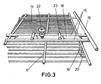
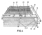
- the operative end (20) of the sliding bar (18) is able to adopt two limit positions, one in which it is retracted with respect to the girder (15), as may be seen in Figure 3 , and another in which it juts out over same, as may be seen in Figure 4 , whereas these two limit positions are stabilised by the existence of a blocking element (22) mounted on the bar itself (18) and able to accommodate both sides of the girder (17'), stopping the latter, as may also be seen in the aforementioned figures 3 and 4 .
- Each pair of crossbars (16) is also stiffened by a pair of upper rounds (23), which could act as limit stops for the blocking element (22), although in the example represented in the figures, the displacement of the sliding bar (18) is limited by the incidence of its first elbow either on the nearest girder (17) or on the outer girder (15).
- the lid (14) includes four sliding bars (18), corresponding to four blocking points for this lid with respect to the body of the container, but evidently this number may vary and be higher or lower without affecting the essence of the invention.
Description
- The present invention refers to a bottle container, of the type formed by a prismatic-rectangular metal box, with a rigid angular frame, onto which metal grids are attached, thereby forming the faces of the container, so that the latter, when conveniently loaded with bottles, is liable to adopt two working positions in which the bottles are laid horizontally and vertically, whereas there are supports for both of these positions, allowing the containers to be placed on the floor or stacked together.
- The object of the invention is to improve the structure of this type of containers, with a view to avoiding handling problems that occur when that handling is carried out by robots.
- This same applicant holds the Spanish utility model
ES 103679 claim 1, i.e. a robust metallic frame corresponding to the angles of the rectangular prism formed by the container, which is the support for a series of interlaced rods which in turn form the closed faces of the container, whereas a drop door is established on one of these faces, namely, one of the lateral faces, affecting the upper half of this face, equipped with fastening bolts, whereas there is an upper grid that functions as a lid to hold in the bottles when the container moves sideways, which is also fastened with bolts which, like the above-mentioned, tend to remain closed due to the effect of respective springs. - Furthermore, at the base of the container and also on one of its lateral faces, the one opposite the door, there are supporting runners which allow to slide and move the container on the floor or on conveyor platforms, so that no matter which position the container adopts, i.e. whether the bottles are horizontal or vertical, it is always supported by the aforementioned runners, which also create a convenient distance between the container and the floor, allowing to introduce the fork of a lift truck.
- However, this type of bottle container, which offers excellent functional features from the theoretical point of view, presents structural and handling problems in practice, which are for the most part based on the following aspects:
- Although the use of arms for the fork on the lift truck is recommended, whose length should be at least the same as the width of the container, in practice and in many cases the arms or catches that are used are considerably shorter, which although the container is not at risk of falling while being handled, does mean that the metallic grid on which they are supported is deformed, meaning that the container loses its theoretical geometry and when the bottles are being handled by a robotised system, given that they are moved slightly more sideways than they should be, handling errors occur as the robot's catches close without supporting the necks of the bottles and are functionally inoperative.
- The container is loaded with the opening facing upwards, position in which it is supported by a pair of runners, and then it is turned 90°, so that it is now supported by the runners that are situated on one of its faces, the one opposite the side door, so that from this position, in which the bottles are lying down, the container is then handled on roller platforms that make it easier to move the container. The existence of just two runners on this face of the container allows it to be moved correctly on the roller platform when in position but this movement is impossible if, for any reason, the support position on the platform is turned 90°, as in this case the runners are parallel to the rollers and these elements are blocked.
- As the bolts stay in the closed position due to the effect of the springs, one of the springs could accidentally break or the bolt could retract due to a blow or any other cause, thereby accidentally disconnecting the grid lid or even the side door itself.
- The bottle container proposed by this invention is based on the aforementioned utility model and includes a series of improvements that fully solve the aforementioned problems. This is achieved by means of a bottle container according to appended
claim 1. - To this end, to be more specific and in accordance with one of the characteristics of the invention, diagonal stiffening bars are placed on the side wall of the container opposite the door, on which in any case the arms or catches of the fork lift are to rest, whether they are short or long, so that it is the stiffening bars that bear the weight of the container's load and undesirable deformation of the metal grid, which constitutes the closure of this face is avoided.
- In accordance with another characteristic of the invention, on this same side face of the container and as well as the two classical runners situated on the parallel edges, there are two more runners on the other two edges of the same face, so that the container may be moved on a roller platform in any position, no matter how the container is placed on the roller platform.
- Finally and in accordance with another characteristic of the invention, a substantial modification has been proposed for the mechanism that fastens the lid, including modifications to the lid itself and to the side walls of the container to which the latter is attached.
- More specifically and maintaining the aforementioned bolt system, which may be adapted to cases where the necks of the bottles come out through the lid, the proposal is that the bars that receive the shanks of the afore-mentioned bolts should include, as well as at least one vertical line of holes to selectively receive the bolts, a middle line of transversal slots intended to selectively receive the bars that slide over the lid itself, more specifically, where each of them will be guided between a pair of bars, at intervals equal to those of the bars, forming a guide that is closed at the bottom by the grid of the lid itself and on the top with the collaboration of a pair of transversal rounds, which also act as slide limit stops for the bars, which include in the intermediate area between both stops a blocking element which determines that the bar is in turn blocked in the open or closed position, depending on which side of the bars of the grid it is situated.
- More specifically, the outer end of the sliding bar is doubly and orthogonally elbowed, first downwards and then outwards, so that the free end fits into one of the slots of the corresponding matching bar to the side wall of the container, thereby allowing to adjust the height of the lid to suit different sizes of bottles and turn the bottle container into a "universal" element.
- In order to complete the description and with the aim of allowing for a better understanding of the characteristics of this invention, according to an example of the preferred embodiment of same, a set of drawings is attached as an integral part of this description, representing the following in an illustrative and non-restrictive manner:
-
Figure 1 .- Shows a perspective view of a bottle container manufactured in accordance with the object of this invention, with the lid unattached. -
Figure 2 .- Shows an enlarged detail of the bars that reinforce the side face supporting the container. -
Figure 3 .- Shows a perspective detail of the lid of the bottle container with the two sliding bars and in an inoperative or open situation for same. -
Figure 4 .- Shows a detail that is similar to that ofFigure 3 , in which the sliding bars are shown in the locked position. -
Figure 5 .- Shows a partial detail of the bottle container as a whole, with the lid also in the closed position. - In the aforementioned figures and especially in
Figure 1 , we can see that the bottle container in question is structured, in the conventional manner, based on a metallic frame (1) that forms the angles of an imaginary rectangular prism, open at the top, whose floor and side walls are closed by means of the respective metallic grids (2), whose lower base rests on two lateral and parallel runners (3) that make it easier to move the container along the floor and at the same time raise the base conveniently so as to allow the catches or arms of a lift truck to pass underneath and that there is a drop door (4) on one of the side walls, which affects approximately the upper half of same and is kept in a stable closed position by means of bolts (5), incorporating on the lateral wall that is opposite the aforementioned door (4) another two lateral and parallel runners (6), on the same plane as the aforementioned runners (3), which in turn allow to slide the container when it has rotated to the horizontal bottle position and that there is a lid (7) similarly manufactured of a metallic grid with bolts (8) which are identical or similar to the aforementioned bolts (5) and that in this case cross through perforated bars (9), conveniently welded to the lateral walls of the container beside the door (4), whereas both types of bolts are retractable against the tension of respective springs that tend to keep them in the closed position. - In accordance with the invention, the side wall (10) of the container opposite the door (4) includes strong diagonal bars (11), placed between its corners, which with the collaboration of an intermediate crossbar (12) ensure maximum structural rigidity on this face, thereby avoiding that when the catches or arms on a lift truck function, even when they are short, the metal grid that closes the bottles for this lateral wall (10) should be deformed.
- Furthermore, on this same lateral wall (10), as well as the two traditional parallel runners (6), there are two other similar runners (13), corresponding to the other two edges, so that no matter which position the container is placed on a roller platform, there will always be runners (6-13) on this side transversal to the rollers of the platform, that will ensure it is easy to move the container.
- Instead of the lid (7) with the traditional bolts (8), specifically when the necks of the bottles should not cross through this lid and with a view to allowing to position this lid according to the different sizes of bottles, a second gridded lid (14) may be attached to the container, with rods that are considerably closer to each other, with the particularity in this case that the lid includes, in correspondence with each of its closing edges, a girder (15), considerably dephased outwardly and upwardly, to which the ends of a series of crossbars (16) are fixed, which are superimposed on the lid itself and fixed to same, preferably forming two pairs in which the crossbars are substantially close together and, with the collaboration of the girders (17-17'), form a guide or rail for a sliding bar (18), whose outer end is orthogonally and downwardly angled, determining a wide vertical descending section (19), and a second outward angle, determining a terminal section (20) which functions like a blocking element on the corresponding bar (9), which in this case and as well as the holes (21) for selective reception of the traditional bolts (8) if the lid (7) is being used, includes a vertical line of slots (21) that are able to selectively receive the operative end (20) of the sliding bar (18), as may be specially seen in
Figure 5 , allowing in turn to adjust the height of the lid (14). - Consequently, the operative end (20) of the sliding bar (18) is able to adopt two limit positions, one in which it is retracted with respect to the girder (15), as may be seen in
Figure 3 , and another in which it juts out over same, as may be seen inFigure 4 , whereas these two limit positions are stabilised by the existence of a blocking element (22) mounted on the bar itself (18) and able to accommodate both sides of the girder (17'), stopping the latter, as may also be seen in the aforementionedfigures 3 and4 . - Each pair of crossbars (16) is also stiffened by a pair of upper rounds (23), which could act as limit stops for the blocking element (22), although in the example represented in the figures, the displacement of the sliding bar (18) is limited by the incidence of its first elbow either on the nearest girder (17) or on the outer girder (15).
- In the example of practical embodiment represented in the figures, the lid (14) includes four sliding bars (18), corresponding to four blocking points for this lid with respect to the body of the container, but evidently this number may vary and be higher or lower without affecting the essence of the invention.
Claims (4)
- A bottle container, of the type formed by a metallic rectangular prismatic body, open at the top and with a pair of runners (3) at its base, a drop door on one of its side walls and on the opposite side wall, a second pair of runners (6), which like the lower runners (3), separate the corresponding face from the floor or supporting plane; a body which is complemented by a lid (7) in the form of a metallic grid that may be attached to the opening of the body with the collaboration of retractable bolts (8), characterised by the fact that on the side wall opposite that of the drop door (4) there are robust diagonal stiffening bars (11), which preferably come together over an intermediate crossbar (12), forming a rigid supportive structure for the catches or arms on the fork lift truck, when the latter are short, measuring less than the width of the container, and that on the same side wall holding the second pair of runners (6), there are another two runners (13), corresponding to the other two edges, which ensure optimum movement of the container on a roller platform, no matter which position the container adopts on the platform.
- A bottle container, according to the 1 st claim, characterised by the fact that the lid (7) includes, in correspondence with each pair of perforated side bars (9) which receive the bolts (8) that close the lid (7), two pairs of crossbars (16) which function as sliding rails for sliding bars (18), with a double orthogonal elbow (19-20) on their outer ends, the former pointing downwards (19) and the second pointing outwards (20), so that the free end of each of the sliding bars (18) is liable to fit selectively into a transversal slot (21) on the corresponding lateral bar (9) on the body of the container, along which a line of slots is also established in longitudinal alignment, with a view to adjusting the height of the lid (7) in the locked position at will.
- A bottle container, according to the 2nd claim, characterised by the fact that the aforementioned crossbars (16) that function as rails for the sliding bars (18) have two girders (15) on their outer ends, which constitute limit stops for outward movement of these bars (18), while under these crossbars there is another girder (17), significantly behind the latter, which in turn constitutes the limit stop for retraction of the sliding bars (18).
- A bottle container, according to the 2nd claim, characterised by the fact that each sliding bar (18) includes a blocking element (22) established on same, able to act on both sides of a third girder (17) established on the lid, blocking this bar (18) in the open or closed position for the operative end of same.
Applications Claiming Priority (2)
| Application Number | Priority Date | Filing Date | Title |
|---|---|---|---|
| ES200202305U | 2002-09-26 | ||
| ES200202305U ES1052864Y (en) | 2002-09-26 | 2002-09-26 | BOTTLE CONTAINER. |
Publications (2)
| Publication Number | Publication Date |
|---|---|
| EP1403189A1 EP1403189A1 (en) | 2004-03-31 |
| EP1403189B1 true EP1403189B1 (en) | 2010-07-21 |
Family
ID=8502150
Family Applications (1)
| Application Number | Title | Priority Date | Filing Date |
|---|---|---|---|
| EP20020380237 Expired - Lifetime EP1403189B1 (en) | 2002-09-26 | 2002-11-21 | Bottle container |
Country Status (4)
| Country | Link |
|---|---|
| EP (1) | EP1403189B1 (en) |
| DE (1) | DE60237082D1 (en) |
| ES (2) | ES1052864Y (en) |
| PT (1) | PT1403189E (en) |
Families Citing this family (3)
| Publication number | Priority date | Publication date | Assignee | Title |
|---|---|---|---|---|
| ES2311434B1 (en) * | 2008-07-02 | 2010-01-05 | Alberto Biurrun Ursua | STRUCTURE TO STABILIZE BOTTLES DISPOSED IN FLOORS. |
| KR200458094Y1 (en) * | 2009-03-02 | 2012-01-19 | 김문환 | For a block of synthetic rubber packing box |
| FR3063979B1 (en) * | 2017-03-20 | 2021-06-11 | Renault Sas | INTERCAL DEVICE FOR TRANSPORT BOX AND BOX EQUIPPED WITH THIS DEVICE |
Family Cites Families (4)
| Publication number | Priority date | Publication date | Assignee | Title |
|---|---|---|---|---|
| US2622830A (en) * | 1950-06-16 | 1952-12-23 | Tri State Engineering Company | Load supporting pallet and crate structure |
| FR2614007B2 (en) * | 1984-04-06 | 1989-10-27 | Diffusion Methode Champen Cent | GROUPING SUPPORT FOR THE SIMULTANEOUS TREATMENT OF A LARGE NUMBER OF BOTTLES ACCORDING TO THE CHAMPENOISE METHOD |
| ES1036791Y (en) * | 1997-03-25 | 1998-04-01 | Sagarte Sa | PERFECTED CONTAINER-BOTTLE UNIT. |
| DE60003277T2 (en) * | 2000-01-19 | 2004-04-22 | Sagarte S.A., Lacunza | Removable wire mesh container to hold bottles |
-
2002
- 2002-09-26 ES ES200202305U patent/ES1052864Y/en not_active Expired - Fee Related
- 2002-11-21 EP EP20020380237 patent/EP1403189B1/en not_active Expired - Lifetime
- 2002-11-21 DE DE60237082T patent/DE60237082D1/en not_active Expired - Lifetime
- 2002-11-21 PT PT02380237T patent/PT1403189E/en unknown
- 2002-11-21 ES ES02380237T patent/ES2349664T3/en not_active Expired - Lifetime
Also Published As
| Publication number | Publication date |
|---|---|
| ES1052864Y (en) | 2003-10-16 |
| ES1052864U (en) | 2003-02-16 |
| EP1403189A1 (en) | 2004-03-31 |
| PT1403189E (en) | 2010-10-25 |
| DE60237082D1 (en) | 2010-09-02 |
| ES2349664T3 (en) | 2011-01-10 |
Similar Documents
| Publication | Publication Date | Title |
|---|---|---|
| US8875909B2 (en) | Device for transporting objects | |
| AU2014203159B2 (en) | Container roll out warehousing system | |
| US4168780A (en) | Flow rail rack | |
| US5111950A (en) | Shipping container | |
| JPH066237U (en) | Glass plate pallet | |
| WO2006005920A1 (en) | Over-length log rack | |
| US4106626A (en) | Stackable material handling container | |
| US20140190964A1 (en) | Intermodal Container | |
| US4952114A (en) | Device for transporting adjusting frames for scaffolding | |
| EP1403189B1 (en) | Bottle container | |
| US8157490B2 (en) | Method of securing freight containers on deck of ship, and spring lashing bar, space adjuster and securing system used in the method | |
| SK134495A3 (en) | Transport container | |
| CA2657403A1 (en) | Racking system and method of storing palletized items | |
| WO2011020134A1 (en) | Collapsible shipping bin of variable capacity | |
| EP2542485B1 (en) | A plant for storing products | |
| US5220980A (en) | Guard for operator of palletized loads | |
| EP2820203B1 (en) | Rostrum support structure | |
| SK6502002A3 (en) | Pallet for elongated goods | |
| AT16968U1 (en) | ||
| CN218662890U (en) | Eccentric tray convenient for roller way transportation of ultra-wide sections | |
| CN216735594U (en) | Auto-parts transportation string formula commodity circulation frame | |
| JP2656756B2 (en) | Pipe frame type container | |
| SU1722960A1 (en) | Pallet | |
| KR200191100Y1 (en) | A lift for transporting package box for plate glass | |
| JPS6246651Y2 (en) |
Legal Events
| Date | Code | Title | Description |
|---|---|---|---|
| PUAI | Public reference made under article 153(3) epc to a published international application that has entered the european phase |
Free format text: ORIGINAL CODE: 0009012 |
|
| AK | Designated contracting states |
Kind code of ref document: A1 Designated state(s): AT BE BG CH CY CZ DE DK EE ES FI FR GB GR IE IT LI LU MC NL PT SE SK TR |
|
| AX | Request for extension of the european patent |
Extension state: AL LT LV MK RO SI |
|
| 17P | Request for examination filed |
Effective date: 20040922 |
|
| AKX | Designation fees paid |
Designated state(s): DE ES FR IT PT |
|
| 17Q | First examination report despatched |
Effective date: 20090709 |
|
| GRAP | Despatch of communication of intention to grant a patent |
Free format text: ORIGINAL CODE: EPIDOSNIGR1 |
|
| GRAS | Grant fee paid |
Free format text: ORIGINAL CODE: EPIDOSNIGR3 |
|
| GRAA | (expected) grant |
Free format text: ORIGINAL CODE: 0009210 |
|
| AK | Designated contracting states |
Kind code of ref document: B1 Designated state(s): DE ES FR IT PT |
|
| REF | Corresponds to: |
Ref document number: 60237082 Country of ref document: DE Date of ref document: 20100902 Kind code of ref document: P |
|
| REG | Reference to a national code |
Ref country code: ES Ref legal event code: FG2A Effective date: 20101227 |
|
| PLBE | No opposition filed within time limit |
Free format text: ORIGINAL CODE: 0009261 |
|
| STAA | Information on the status of an ep patent application or granted ep patent |
Free format text: STATUS: NO OPPOSITION FILED WITHIN TIME LIMIT |
|
| 26N | No opposition filed |
Effective date: 20110426 |
|
| REG | Reference to a national code |
Ref country code: DE Ref legal event code: R097 Ref document number: 60237082 Country of ref document: DE Effective date: 20110426 |
|
| REG | Reference to a national code |
Ref country code: FR Ref legal event code: ST Effective date: 20110801 |
|
| REG | Reference to a national code |
Ref country code: DE Ref legal event code: R119 Ref document number: 60237082 Country of ref document: DE Effective date: 20110601 Ref country code: DE Ref legal event code: R119 Ref document number: 60237082 Country of ref document: DE Effective date: 20110531 |
|
| PG25 | Lapsed in a contracting state [announced via postgrant information from national office to epo] |
Ref country code: FR Free format text: LAPSE BECAUSE OF NON-PAYMENT OF DUE FEES Effective date: 20101130 |
|
| PGFP | Annual fee paid to national office [announced via postgrant information from national office to epo] |
Ref country code: PT Payment date: 20120521 Year of fee payment: 11 Ref country code: IT Payment date: 20121113 Year of fee payment: 11 |
|
| PG25 | Lapsed in a contracting state [announced via postgrant information from national office to epo] |
Ref country code: DE Free format text: LAPSE BECAUSE OF NON-PAYMENT OF DUE FEES Effective date: 20110531 |
|
| REG | Reference to a national code |
Ref country code: PT Ref legal event code: MM4A Free format text: LAPSE DUE TO NON-PAYMENT OF FEES Effective date: 20140521 |
|
| PG25 | Lapsed in a contracting state [announced via postgrant information from national office to epo] |
Ref country code: PT Free format text: LAPSE BECAUSE OF NON-PAYMENT OF DUE FEES Effective date: 20140521 Ref country code: IT Free format text: LAPSE BECAUSE OF NON-PAYMENT OF DUE FEES Effective date: 20131121 |
|
| PGFP | Annual fee paid to national office [announced via postgrant information from national office to epo] |
Ref country code: ES Payment date: 20191223 Year of fee payment: 18 |
|
| REG | Reference to a national code |
Ref country code: ES Ref legal event code: FD2A Effective date: 20220202 |
|
| PG25 | Lapsed in a contracting state [announced via postgrant information from national office to epo] |
Ref country code: ES Free format text: LAPSE BECAUSE OF NON-PAYMENT OF DUE FEES Effective date: 20201122 |