EP1403171A1 - Three-wheeled vehicle provided with swinging mechanism - Google Patents
Three-wheeled vehicle provided with swinging mechanism Download PDFInfo
- Publication number
- EP1403171A1 EP1403171A1 EP20030020604 EP03020604A EP1403171A1 EP 1403171 A1 EP1403171 A1 EP 1403171A1 EP 20030020604 EP20030020604 EP 20030020604 EP 03020604 A EP03020604 A EP 03020604A EP 1403171 A1 EP1403171 A1 EP 1403171A1
- Authority
- EP
- European Patent Office
- Prior art keywords
- attached
- swinging
- shaft
- suspension arms
- body frame
- Prior art date
- Legal status (The legal status is an assumption and is not a legal conclusion. Google has not performed a legal analysis and makes no representation as to the accuracy of the status listed.)
- Granted
Links
Images






Classifications
-
- B—PERFORMING OPERATIONS; TRANSPORTING
- B62—LAND VEHICLES FOR TRAVELLING OTHERWISE THAN ON RAILS
- B62K—CYCLES; CYCLE FRAMES; CYCLE STEERING DEVICES; RIDER-OPERATED TERMINAL CONTROLS SPECIALLY ADAPTED FOR CYCLES; CYCLE AXLE SUSPENSIONS; CYCLE SIDECARS, FORECARS, OR THE LIKE
- B62K5/00—Cycles with handlebars, equipped with three or more main road wheels
- B62K5/02—Tricycles
- B62K5/027—Motorcycles with three wheels
-
- B—PERFORMING OPERATIONS; TRANSPORTING
- B60—VEHICLES IN GENERAL
- B60G—VEHICLE SUSPENSION ARRANGEMENTS
- B60G21/00—Interconnection systems for two or more resiliently-suspended wheels, e.g. for stabilising a vehicle body with respect to acceleration, deceleration or centrifugal forces
- B60G21/007—Interconnection systems for two or more resiliently-suspended wheels, e.g. for stabilising a vehicle body with respect to acceleration, deceleration or centrifugal forces means for adjusting the wheel inclination
-
- B—PERFORMING OPERATIONS; TRANSPORTING
- B62—LAND VEHICLES FOR TRAVELLING OTHERWISE THAN ON RAILS
- B62D—MOTOR VEHICLES; TRAILERS
- B62D9/00—Steering deflectable wheels not otherwise provided for
- B62D9/02—Steering deflectable wheels not otherwise provided for combined with means for inwardly inclining vehicle body on bends
-
- B—PERFORMING OPERATIONS; TRANSPORTING
- B62—LAND VEHICLES FOR TRAVELLING OTHERWISE THAN ON RAILS
- B62K—CYCLES; CYCLE FRAMES; CYCLE STEERING DEVICES; RIDER-OPERATED TERMINAL CONTROLS SPECIALLY ADAPTED FOR CYCLES; CYCLE AXLE SUSPENSIONS; CYCLE SIDECARS, FORECARS, OR THE LIKE
- B62K5/00—Cycles with handlebars, equipped with three or more main road wheels
- B62K5/10—Cycles with handlebars, equipped with three or more main road wheels with means for inwardly inclining the vehicle body on bends
-
- B—PERFORMING OPERATIONS; TRANSPORTING
- B60—VEHICLES IN GENERAL
- B60G—VEHICLE SUSPENSION ARRANGEMENTS
- B60G2204/00—Indexing codes related to suspensions per se or to auxiliary parts
- B60G2204/40—Auxiliary suspension parts; Adjustment of suspensions
- B60G2204/421—Pivoted lever mechanisms for mounting suspension elements, e.g. Watt linkage
-
- B—PERFORMING OPERATIONS; TRANSPORTING
- B60—VEHICLES IN GENERAL
- B60G—VEHICLE SUSPENSION ARRANGEMENTS
- B60G2204/00—Indexing codes related to suspensions per se or to auxiliary parts
- B60G2204/80—Interactive suspensions; arrangement affecting more than one suspension unit
- B60G2204/82—Interactive suspensions; arrangement affecting more than one suspension unit left and right unit on same axle
-
- B—PERFORMING OPERATIONS; TRANSPORTING
- B60—VEHICLES IN GENERAL
- B60G—VEHICLE SUSPENSION ARRANGEMENTS
- B60G2204/00—Indexing codes related to suspensions per se or to auxiliary parts
- B60G2204/80—Interactive suspensions; arrangement affecting more than one suspension unit
- B60G2204/83—Type of interconnection
- B60G2204/8302—Mechanical
-
- B—PERFORMING OPERATIONS; TRANSPORTING
- B60—VEHICLES IN GENERAL
- B60G—VEHICLE SUSPENSION ARRANGEMENTS
- B60G2300/00—Indexing codes relating to the type of vehicle
- B60G2300/12—Cycles; Motorcycles
- B60G2300/122—Trikes
-
- B—PERFORMING OPERATIONS; TRANSPORTING
- B60—VEHICLES IN GENERAL
- B60G—VEHICLE SUSPENSION ARRANGEMENTS
- B60G2300/00—Indexing codes relating to the type of vehicle
- B60G2300/45—Rolling frame vehicles
-
- B—PERFORMING OPERATIONS; TRANSPORTING
- B60—VEHICLES IN GENERAL
- B60G—VEHICLE SUSPENSION ARRANGEMENTS
- B60G2800/00—Indexing codes relating to the type of movement or to the condition of the vehicle and to the end result to be achieved by the control action
- B60G2800/01—Attitude or posture control
- B60G2800/019—Inclination due to load distribution or road gradient
- B60G2800/0194—Inclination due to load distribution or road gradient transversal with regard to vehicle
Definitions
- the present invention relates to a three-wheeled vehicle provided with a swinging mechanism in which a cost for ride comfort is reduced, enhancing ride comfort.
- a three-wheeled vehicle provided with a swinging mechanism in which right and left rear wheels are coupled via a shaft is known (for example, refer to a patent document 1).
- Patent document 1
- Fig. 2 of the patent document 1 will be described referring to Fig. 19 below and Fig. 3 of the patent document 1 will be described referring to Fig. 20 below. Reference numbers are newly allocated.
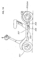
- Fig. 19 is a side view showing a conventional type three-wheeled vehicle provided with a swinging mechanism and shows the three-wheeled vehicle provided with the swinging mechanism in which a front frame 202 provided with one front wheel 201 and a rear frame 205 provided with right and left rear wheels 203, 204 are coupled via a pivot coupling device 206.
- the pivot coupling device 206 is composed of a housing attached to the front frame 202 and a pivot the front of which is rotatably attached to the housing and the rear of which is attached to the rear frame 205, and the front frame 202 can be rolled around a pivot axis 207 for the rear frame 205.
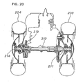
- Fig. 20 is a sectional view showing the rear of the conventional type three-wheeled vehicle provided with the swinging mechanism and shows that one end of an intermediate shaft 212 is connected to a rear wheel shaft 211 to which one rear wheel 203 is attached via splines, the other rear wheel shaf t 214 is attached to the other end of the intermediate shaft 212 via friction differential gears 213 and the other rear wheel 204 is attached to the rear wheel shaft 214.
- the three-wheeled vehicle is provided with thepivot for swinging the front frame 202 crosswise, however, the three-wheeled vehicle is provided with no swinging shaft for vertically swinging the rear wheels 203, 204.
- the number of parts is increased and the cost is increased.
- the rear wheel 203 is lifted upward when one rear wheel 203 runs on a convex portion of a road in running for example, the effect is transmitted to the other rear wheel 204 via the rear wheel shaft 211, the intermediate shaft 212 and the rear wheel shaft 214, the rear wheel 204 is inclined, the rear frame 205 shown in Fig. 19 is rolled and the front frame 202 is vertically moved by the roll.
- Such configuration causes no trouble in a vehicle the displacement of which is small, however, in a vehicle the displacement of which is middle or more and in which high-speed driving is also enabled, the improvement of ride comfort is desired.
- the object of the invention is to reduce a cost for ride comfort, enhancing the ride comfort of a three-wheeled vehicle provided with a swinging mechanism.
- Claim 1 is based upon a three-wheeled vehicle provided with a swinging mechanism in which right and left rear wheels are attached to the right and the left of a body frame via suspension arms so that the rear wheels can be vertically moved and the swinging mechanism for allowing the lateral swing of the body frame for the side of the suspension arm is provided between the side of the suspension arm and the side of the body frame and is characterized in that a spindle extended in a longitudinal direction of the body is attached to the body frame, the right and left suspension arms are independently attached to the spindle so that the suspension arms can be vertically swung and the spindle also functions as a swinging shaft for swinging the body frame.
- each rear wheel can be independently vertically moved without lateral interference by supporting the right and left rear wheels by the spindle via the suspension arms mutually independent, compared with the conventional type in which the right and left rear wheels are coupled via an axle for example, the followability of the right and left rear wheels after a road is increased, the roll of the body can be reduced and its ride comfort can be enhanced.
- the number of parts can be reduced, compared with a case that right and left suspension arms are attached to separate swinging shafts and the cost can be reduced. Further, as the spindle also functions as a swinging shaft, the number of parts can be reduced, compared with a case that a spindle and a swinging shaft are separately provided and the cost can be more reduced.
- Claim 2 is characterized in that a suspension arm is an A-type arm.
- the suspension arm is A-type, the rigidity of the suspension arm can be enhanced and running stability can be enhanced.
- FIG. 1 is a side view showing a three-wheeled vehicle provided with a swinging mechanism according to the invention.
- the three-wheeled vehicle provided with the swinging mechanism 10 (hereinafter called the three-wheeled vehicle 10) is composed of a front fork 12 steerably attached to a head pipe 11 via a steering shaft not shown, a front wheel 13 attached to the lower end of the front fork 12, a handlebar 14 integrated with the front fork 12, a body frame 16 attached to the rear of the head pipe 11, a power unit 17 attached to the rear of the body frame 16 , right and left rear wheels 21, 18 driven by the power unit 17, a housing box 22 attached to an upper part of the body frame 16 and a seat 23 openably attached to an upper part of the housing box 22.
- the body frame 16 is composed of a down pipe 25 extended backward and diagonally downward from the head pipe 11, a pair of right and left lower pipes 27, 26 extended backward from a lower part of the down pipe 25 and further, extended backward and diagonally upward, a center upper frame 28 coupled to the respective rears of these lower pipes 27, 26 a center pipe 31 extended backward from the down pipe 25 and coupled to the center upper frame 28 and a J-shaped frame 32 when it is viewed from the side coupled to the rear of each lower pipe 27, 26 and the rear side of the center upper frame 28.
- the center upper frame 28 is a member for supporting the housing box 22 and suspending the power unit 17.
- the J-shaped frame 32 is a member for attaching a rear suspension that suspends the rear wheels 18, 21 and the swinging mechanism allowing a lateral swing on the side of the body frame 16 for the side of the rear suspension.
- the rear suspension and the swinging mechanism will be described in detail later.
- the power unit 17 is composed of an engine 34 arranged on the front side of the body and a transmission mechanism 35 that transmits the power of the engine 34 to the rear wheels 18, 21.
- a reference number 41 denotes a front fender that covers the front wheel 13
- 42 denotes a battery
- 43 denotes a winker
- 44 denotes a tail lamp
- 46 denotes an air cleaner
- 47 denotes a muffler.
- Fig. 2 is a side view showing a main part of the three-wheeled vehicle according to the invention.
- Fig. 2 shows that the rear of the power unit 17 is supported by laying each coupling pipe 52, 52 (the inside coupling pipe 52 is not shown) between the J-shaped frame 32 and the center upper frame 28 to couple an upper part of the J-shaped frame 32 and the rear ends of the center upper frame 28, attaching each reinforcing plate 53, 53 to each coupling pipe 52, 52 and the center upper frame 28, attaching an L-type pipe 54 of substantially an L type when it is viewed from the side to the inside of the rear of the J-shaped frame 32, attaching brackets 56, 56 (the inside bracket 56 is not shown) to the center upper frame 28, attaching an upper part of the front of the power unit 17 to these brackets 56, 56 via an intermediate member 57 and extending a supporting rod 58 from the reinforcing plates 53, 53 downward and diagonally backward, and shows that the rear end of the power unit 17 is attached by extending a projection
- Reference numbers 32A, 32B, 32C denote a substantially horizontal lower horizontal part of the J-shaped frame 32, an inclined part at the rear end the upper end side of which is extended at the back of the lower end side and an upper inclined part the front end of which is higher than the rear end.
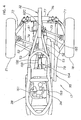
- Fig. 3 is a plan showing the three-wheeled vehicle according to the invention and shows that the rear of the J-shaped frame 32 is formed by one pipe and a rear suspension 63 (the details will be described later) is attached to the J-shaped frame 32.
- a reference number 65 denotes a brake lever for the rear wheel and 66 denotes a brake lever for the front wheel.
- Fig. 4 is a plan showing the main part of the three-wheeled vehicle according to the invention.
- Fig. 4 shows structure that suspension arms 71, 72 are attached to the right and the left of the J-shaped frame 32, holders (not shown) are attached to the ends of these suspension arms 71, 72, the rear wheels 18, 21 are rotatably attached to these holders and these rear wheels 18, 21 are driven by drive shafts 73, 74 extended from transmission mechanism 35 of the power unit 17.
- a ref erence number 76 denotes a shock absorber as resilient means composed of a damper 77 and a helical compression spring (not shown) and the shock absorber is coupled to the respective sides of the right and left suspension arms 72, 71.
- the center upper frame 28 is a circular or a substantially elliptic member and the housing box 22 (see Fig. 1) having a substantially similar bottom is attached to its upper part.
- the transmission mechanism 35 of the power unit 17 is composed of a belt-type continuously variable transmission 78 extended backward from the rear of the left of the engine 34 and a gear box 81 coupled to the rear of the continuously variable transmission 78, the drive shaft 74 is connected to the output shaft on the front side of the gear box 81 and the drive shaft 73 is connected to the output shaft on the rear side of the gear box 81.
- Fig. 5 is a first perspective view showing the three-wheeled vehicle according to the invention and shows that the front of the J-shaped frame 32 is attached to the respective rears of the lower pipes 26, 27 of the body frame 16 .
- a reference number 83 denotes a holder (the inside holder 83 is not shown).
- Fig. 6 is a back view showing the three-wheeled vehicle according to the invention, the inclined part at the rear end 32B of the J-shaped frame 32 is a substantially perpendicular part in a state in which nobody rides on the three-wheeled vehicle 10 and the rears of the suspension arms 71, 72 are attached to the inclined part at the rear end 32B.
- a reference number 85 denotes a rear swing shaft for swingably attaching the rears of the suspension arms 71, 72 to the inclined part at the rear end 32B.
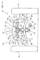
- Fig. 7 is a second perspective view showing the three-wheeled vehicle according to the invention and shows the rear suspension 63 in which the suspension arms 72, 71 are extended right and left from the J-shaped frame 32, the holders 83 are attached to the respective ends of these suspension arms 72, 71, arc-shaped links 89, 88 as a coupling means are swingably attached to the respective upper parts of the suspension arms 72, 71 via mounting brackets 87, 86, bell cranks 91, 90 as a coupling means of a substantially L type when they are viewed from the side are swingably attached to the respective ends of these arc-shaped links 89, 88, the shock absorber 76 is laid between the respective upper ends of these bell cranks 91, 90, a bar-shaped connecting member 92 is laid between the respective ends of the sides of the bell cranks 91, 90 and the connecting member 92 is attached to the inclined part at the rear end 32B of the J-shaped frame 32 via the swinging mechanism 93.
- the arc-shaped links 88, 89 are respectively provided with a side protruded part 95 in the middle and brake calipers 96, 96 for braking each swing of the arc-shaped links 88, 89 are attached to these side protrudedparts 95 .
- Reference numbers 97, 97 denote a braking device provided with the brake caliper 96 and each disc 98, 98 is held between the brake calipers 96, 96 by oil pressure.
- the discs 98, 98 are members attached to the suspension arms 71, 72.
- a reference number 100 denotes a bolt that functions as each swinging shaft of the arc-shaped links 88, 89.
- Each bell crank 90, 91 is composed of two crank plates 102, 102 and is provided with a first bolt 103 as a first fulcrum, a second bolt 104 as a second fulcrum and a third bolt 106 as a third fulcrum.
- a reference number 107 denotes a fourth bolt as a stopper pin for regulating the stretch of the shock absorber 76 and 108, --- (---shows plurality, hereinafter similar) denote a nut screwed on the first bolt 103 to the fourth bolt 107.
- the swinging mechanism 93 is a member for allowing the rightward and leftward swings of the body frame 16 for the suspension arms 71, 72 in cornering, increasing reaction force with included elasticity as the inclination of the swing becomes large and returning the body frame to an original position.
- Figs. 8A to 8C are explanatory drawings for explaining the swinging mechanism according to the invention
- Fig. 8A is a side view (a partial sectional view)
- Fig. 8B is a sectional view viewed along a line b-b in Fig. 8A
- Fig. 8C shows action in Fig. 8B.
- Fig. 8A is a side view (a partial sectional view)
- Fig. 8B is a sectional view viewed along a line b-b in Fig. 8A
- Fig. 8C shows action in Fig. 8B.
- the swinging mechanism 93 is so-called "Neidhart damper” composed of a case 111 attached to the inclined part at the rear end 32B of the J-shaped frame 32 and the rear of the L-type pipe 54, damper rubbers 112, --- housed in the case 111, a pressing member 113 attached to the connecting member 92 for pressing these damper rubbers 112, --- and a through pin 116 which pierces the pressing member 113 and the connecting member 92 and both ends of which are supported by an end support 114 provided to the L-type pipe 54 and the inclined part at the rear end 2B.
- a reference number 117 denotes an attachment provided to the pressing member 113 to bolt the pressing member 113 on the connecting member 92 and 118 denotes a swing regulator integrated with the end support 114 to regulate the swing of the connecting member 92.
- the case 111 is a member including a left case 121 and a right case 122, a damper housing 123 is provided to the inside, the damper rubbers 112, --- are arranged at the four corners of the damper housing 123 and are pressed by convex pressing parts 124, --- of the pressing member 113.
- the body frame 16 is swung on the left of the body (an arrow left in Fig. 8C shows the left of the body) for the connecting member 92 coupled to the side of the suspension arm, when the L-type pipe 54 is inclined by an angle ⁇ , the case 111 of the swinging mechanism 93 is relatively revolved with the pressing member 113, the damper rubbers 112, --- housed in the case 111 are compressed between the case 111 and the pressing member 113 and reactive force that tries to return the case 111 and further, the body f rame 16 to each original position (each position shown in Fig. 8A) generates.
- Fig. 9 is a third perspective view (diagonally viewed from the rear of thebody frame) showing the three-wheeled vehicle according to the invention and shows that rear fittings 127 for swingably attaching the respective rears of the suspension arms 71, 72 (see Fig. 7) and front fittings 128 for swingably attaching the respective fronts of the suspension arms 71, 72 are provided to the J-shaped frame 32.
- the rear fittings 127 are composed of the inclined part at the rear end 32B and a vertical bracket 131 connecting the L-type pipe 54 and a lower horizontal part 32E (described later), and the rear swing shaft 85 (see Fig. 6) for supporting the respective rears of the suspension arms 71, 72 is attached to the inclined part at the rear end 32B and the vertical bracket 131.
- the front fittings 128 is composed of a front stand 133 and a rear stand 134 which stand at an interval on the lower horizontal part 32E and a front swing shaft 136 for supporting the respective fronts of the suspension arms 71, 72 is attached to the front stand 133 and the rear stand 134.
- a reference number 138 denotes a fuel tank
- 142 and 143 denote an engine mounting vibration insulating link for mounting the engine 34 on the body frame 16
- 144 denotes a U-shaped pipe attached to a lower part of each rear of the lower pipes 26, 27 to attach the end of the lower horizontal part 32E of the J-shaped frame 32.
- Fig. 5 shows the embodiment that the front ends of the lower horizontal part 32A branched in a Y type are directly attached to the lower pipes 26, 27, however
- Fig. 9 shows another embodiment that the J-shaped frame 32 is composed of the lower horizontal part 32E branched in a Y type, the inclined part at the rear end 32B and an upper inclined part 32C and the front ends of the lower horizontal part 32E are attached to the lower pipes 26, 27 via the U-shaped pipe 144.
- Fig. 10 is a plan showing the body frame according to the invention and shows that the lower horizontal part 32E of the J-shaped frame 32 is branched in a Y type halfway, the branched parts are coupled to the rear of the U-shaped pipe 144 and the coupling pipes 52, 52 are extended in a Y type from the upper inclined part 32C of the J-shaped frame 32 to the center upper frame 28.
- the lower horizontal part 32E (and the lower horizontal part 32A (see Fig. 5)) are detailedly a part formed by bending one long first pipe 151 halfway and connecting a second pipe 153 to the vicinity of a bended part 152 of the first pipe 151.
- a reference number 154 denotes a Y-type branched part acquired by connecting the second pipe 153 to the first pipe 151 and branching in a Y type and 155 denotes a Y-type branched part acquired by connecting the coupling pipes 52, 52 to the upper inclined part 32C and branching in a Y type.
- the first pipe 151 is a member including the inclined part at the rear end 32B and the upper inclined part 32C and is acquired by removing the second pipe 153 from the J-shaped frame 32.
- connection of the front of a lower part of the J-shaped frame 32 and the U-shaped pipe 144 can be enhanced by forming the lower horizontal part 32E in the Y type as described above and the connection of an upper part of the rear of the J-shaped frame 32 and the rear of the center upper frame 28 can be enhanced by arranging the coupling pipes 52, 52 in the Y type.
- the connection of the front of the lower part of the J-shaped frame 32 and the lower pipes 26, 27 can be enhanced by forming the lower horizontal part 32A in the Y type as shown in Fig. 5.
- Fig. 11 is a back view showing the rear suspension according to the invention and shows the rear suspension 63 in a state in which a rider rides the three-wheeled vehicle.
- the inclined part at the rear end 32B and the upper inclined part 32C of the J-shaped frame 32 respectively shown in Fig. 9 are omitted.
- the right case 122 of the swinging mechanism 93 shown in Fig. 8B is shown by an imaginary line.
- the L-type pipe 54 of the body frame 16 is substantially vertical and the connecting member 92 is substantially horizontal.
- the connecting member 92 is a member provided with fan-type parts 156, 157 to each of which each arc-shaped long hole 158, 159 is provided at both ends and the inclination angle of each bell crank 90, 91 with the connecting member 92 is regulated by piercing each fourth bolt 107, 107 as a stopper pin in each arc-shaped long hole 158, 159.
- the inclination angle of the bell cranks 90, 91 varies depending upon the inclination angle of the suspension arms 71, 72, that is, quantity in which the rear wheels 18, 21 are vertically moved.
- the arc-shaped long holes 158, 159 are parts for regulating the quantity in which the rear wheels 18, 21 are vertically moved.
- Fig. 12 is a perspective view showing a state in which the respective fronts of the suspension arms according to the invention are attached (an arrow (front) in Fig. 12 shows a direction toward the front of the body. Hereinafter it is similar) and shows that the end of each front of the suspension arms 71, 72 is turnably attached to the front swinging shaft 136 so that the suspension arm 72 is located at the back of the suspension arm 71.
- the front swinging shaft 136 is a bolt piercing the front stand 133 and the rear stand 134 and a nut 161 is screwed at the end.
- Fig. 13 is a perspective view showing a state in which the respective rears of the suspension arms according to the invention are attached and shows that the end of each rear of the suspension arms 71, 72 is turnably attached to the rear swinging shaft 85 so that the suspension arm 72 is located at the back of the suspension arm 71.
- Fig. 14 shows the first action of the rear suspension according to the invention.
- the suspension arm 71 is swung upward as shown by an arrow a with the rear swing shaft 85 and the front swing shaft 136 (see Fig. 9) in the center, hereby the arc-shaped link 88 is lifted as shown by an arrow b, the bell crank 90 is swung in a direction shown by an arrow c with the second bolt 104 as a fulcrum and the shock absorber 76 is pressed and contracted in a direction shown by an arrow d.
- Fig. 15 shows the second action of the rear suspension according to the invention.
- the suspension arms 71, 72 are swung upward as shown by arrows f, f with the rear swing shaft 85 and the front swing shaft 136 (see Fig.
- Fig. 16 shows the third action of the rear suspension according to the invention.
- the suspension arms 71, 72 are swung downward as shown by arrows m, m with the rear swing shaft 85 and the front swing shaft 136 (see Fig.
- Fig. 17 shows the fourth action of the rear suspension according to the invention.
- the connecting member 92 coupled to the L-type pipe 54 via the through pin 116 is moved in parallel leftward as shown by an arrow s.
- the arc-shaped links 88, 89 are inclined as shown by arrows t, t and the bell cranks 90, 91 are moved in parallel as shown by arrows u, u.
- the shock absorber 76 is not extended/contracted.
- the body frame 16 is swung with the front swinging shaft 136 (see Fig. 12) and the rear swinging shaft 85 respectively swingably supporting the suspension arms 71, 72 in the center.
- the front swinging shaf t 13 6 and the rear swinging shaf t 85 function as a swinging shaft for swinging the body frame 16.
- Fig. 18 shows the fifth action of the rear suspension according to the invention.
- the L-type pipe 54 in this case is swung by an angle ⁇ 2 on the left side of the body from the state shown in Fig. 11, the suspension arm 71 is swung upward as shown by an arrow v with the rear swing shaft 85 and the front swing shaft 136 (see Fig. 9) in the center and the connecting member 92 is moved leftward as shown by an arrow w.
- the arc-shaped link 88 is lifted, is inclined leftward, the arc-shaped link 89 is inclined leftward as shown by an arrow x, the bell crank 90 is swung clockwise with the second bolt 104 as a fulcrum, is moved leftward, the bell crank 91 is moved leftward, as a result presses and contracts the shock absorber 76 and makes buffer action.
- the invention is first characterized in that in the three-wheeled vehicle provided with the swinging mechanism 10 in which the right and left rear wheels 21, 18 are attached to the right and the left of the body frame 16 via the suspension arms 72, 71 so that the rear wheels can be vertically moved and the swinging mechanism 93 (see Fig.
- the rear wheels 21, 18 can be independently vertically moved without lateral interference by supporting the right and left rear wheels 21, 18 by the front swinging shaft 136 and the rear swinging shaft 85 via the mutually independent suspension arms 72, 71, compared with a case that right and left rear wheels are coupled via an axle in the conventional type for example, the followability of the right and left rear wheels 21, 18 after a road is increased, the roll of the body can be reduced and the ride comfort can be enhanced.
- the number of parts can be reduced, compared with a case that right and left suspension arms are attached to separate swinging shafts and the cost can be reduced. Further, as the front swinging shaft 136 and the rear swinging shaft 85 function as a swinging shaft, the number of parts can be reduced, compared with a case that a spindle and a swinging shaft are separately provided and the cost can be more reduced.
- Claim 2 is characterized in that the suspension arms 71, 72 are the A-type arm as shown in Fig. 4. As the suspension arms 71, 72 are A-type, the rigidity of the suspension arms 71, 72 can be enhanced and the running stability can be enhanced.
- the spindle is divided into the front swinging shaft 136 (see Fig. 12) and the rear swinging shaft 85 (see Fig. 13) , however, the invention is not limited to this and the right and left suspension arms 72, 71 may be also swingably attached to one spindle.
- the invention produces the following effect owing to the above-mentioned configuration.
- the right and left suspension arms are mutually independently attached to the spindle so that the suspension arms can be vertically swung and the spindle also functions as a swinging shaft for swinging the body frame
- the rear wheels can be independently vertically moved without lateral interference in the invention by supporting the right and left rear wheels by the spindle via the independent suspension arms, compared with a case that right and left rear wheels are coupled via an axle as in the conventional type for example, the followability of the right and left rear wheels after a road is increased, the roll of the body can be reduced and the ride comfort can be enhanced.
- the number of parts can be reduced, compared with a case that right and left suspension arms are attached to separate swinging shafts and the cost can be reduced. Further, as the spindle also functions as a swinging shaft, the number of parts can be reduced, compared with a case that a spindle and a swinging shaft are separately provided and the cost can be more reduced.
- the suspension arm is the A-type arm
- the rigidi ty of the suspension arm can be enhanced and the running stability can be enhanced.
- a front swinging shaft and a rear swinging shaft 85 respectively as a spindle extended in a longitudinal direction of the body are attached to a body frame 16, right and left suspension arms 72, 71 are mutually independently attached to the front swinging shaft and the rear swinging shaft 85 so that the suspension arms can be vertically swung, and the front swinging shaft and the rear swinging shaft 85 function as a swinging shaft for swinging the body frame 16.
- the rear wheels can be independently vertically moved without lateral interference, compared with a case that right and left rear wheels are coupled via a shaft for example, the followability of the right and left rear wheels after a road is increased, the roll of the body can be reduced and the ride comfort can be enhanced.
- the right and left suspension arms are attached to the same spindle, the number of parts can be reduced and further, as the spindle also functions as the swinging shaft, the cost can be more reduced.
Landscapes
- Engineering & Computer Science (AREA)
- Mechanical Engineering (AREA)
- Chemical & Material Sciences (AREA)
- Combustion & Propulsion (AREA)
- Transportation (AREA)
- Vehicle Body Suspensions (AREA)
- Automatic Cycles, And Cycles In General (AREA)
- Axle Suspensions And Sidecars For Cycles (AREA)
Abstract
Effect: In the invention, the rear wheels can be independently vertically moved without lateral interference, compared with a case that right and left rear wheels are coupled via a shaft for example, the followability of the right and left rear wheels after a road is increased, the roll of the body can be reduced and the ride comfort can be enhanced. As the right and left suspension arms are attached to the same spindle, the number of parts canbe reduced and further, as the spindle also functions as the swinging shaft, the cost can be more reduced.
Description
- The present invention relates to a three-wheeled vehicle provided with a swinging mechanism in which a cost for ride comfort is reduced, enhancing ride comfort.
- A three-wheeled vehicle provided with a swinging mechanism in which right and left rear wheels are coupled via a shaft is known (for example, refer to a patent document 1).
- Japanese published examined patent application No. Sho58-24310 (Figs. 2 and 3 on pp. 1 and 2)
- Fig. 2 of the
patent document 1 will be described referring to Fig. 19 below and Fig. 3 of thepatent document 1 will be described referring to Fig. 20 below. Reference numbers are newly allocated. - Fig. 19 is a side view showing a conventional type three-wheeled vehicle provided with a swinging mechanism and shows the three-wheeled vehicle provided with the swinging mechanism in which a
front frame 202 provided with onefront wheel 201 and arear frame 205 provided with right and leftrear wheels pivot coupling device 206. - The
pivot coupling device 206 is composed of a housing attached to thefront frame 202 and a pivot the front of which is rotatably attached to the housing and the rear of which is attached to therear frame 205, and thefront frame 202 can be rolled around apivot axis 207 for therear frame 205. - Fig. 20 is a sectional view showing the rear of the conventional type three-wheeled vehicle provided with the swinging mechanism and shows that one end of an
intermediate shaft 212 is connected to arear wheel shaft 211 to which onerear wheel 203 is attached via splines, the other rearwheel shaf t 214 is attached to the other end of theintermediate shaft 212 via frictiondifferential gears 213 and the otherrear wheel 204 is attached to therear wheel shaft 214. - As shown in Fig. 19, the three-wheeled vehicle is provided with thepivot for swinging the
front frame 202 crosswise, however, the three-wheeled vehicle is provided with no swinging shaft for vertically swinging therear wheels - As the right and left
rear wheels rear wheel shaft 211, theintermediate shaft 212 and therear wheel shaft 214 as shown in Fig. 20, therear wheel 203 is lifted upward when onerear wheel 203 runs on a convex portion of a road in running for example, the effect is transmitted to the otherrear wheel 204 via therear wheel shaft 211, theintermediate shaft 212 and therear wheel shaft 214, therear wheel 204 is inclined, therear frame 205 shown in Fig. 19 is rolled and thefront frame 202 is vertically moved by the roll. Such configuration causes no trouble in a vehicle the displacement of which is small, however, in a vehicle the displacement of which is middle or more and in which high-speed driving is also enabled, the improvement of ride comfort is desired. - Then, when the swinging shaft is separately provided on the right and on the left, a swing arm is respectively attached to these swinging shafts and the
rear wheels rear wheels - The object of the invention is to reduce a cost for ride comfort, enhancing the ride comfort of a three-wheeled vehicle provided with a swinging mechanism.
- To achieve the object.
Claim 1 is based upon a three-wheeled vehicle provided with a swinging mechanism in which right and left rear wheels are attached to the right and the left of a body frame via suspension arms so that the rear wheels can be vertically moved and the swinging mechanism for allowing the lateral swing of the body frame for the side of the suspension arm is provided between the side of the suspension arm and the side of the body frame and is characterized in that a spindle extended in a longitudinal direction of the body is attached to the body frame, the right and left suspension arms are independently attached to the spindle so that the suspension arms can be vertically swung and the spindle also functions as a swinging shaft for swinging the body frame. - In the invention, each rear wheel can be independently vertically moved without lateral interference by supporting the right and left rear wheels by the spindle via the suspension arms mutually independent, compared with the conventional type in which the right and left rear wheels are coupled via an axle for example, the followability of the right and left rear wheels after a road is increased, the roll of the body can be reduced and its ride comfort can be enhanced.
- As the right and left suspension arms are attached to the same spindle, the number of parts can be reduced, compared with a case that right and left suspension arms are attached to separate swinging shafts and the cost can be reduced.
Further, as the spindle also functions as a swinging shaft, the number of parts can be reduced, compared with a case that a spindle and a swinging shaft are separately provided and the cost can be more reduced. - Claim 2 is characterized in that a suspension arm is an A-type arm.
As the suspension arm is A-type, the rigidity of the suspension arm can be enhanced and running stability can be enhanced. - An embodiment of the invention will be described based upon attached drawings below, in which:
- Fig. 1 is a side view showing a three-wheeled vehicle provided with a swinging mechanism according to the invention;
- Fig. 2 is a side view showing a main part of the three-wheeled vehicle according to the invention;
- Fig. 3 is a plan showing the three-wheeled vehicle according to the invention;
- Fig. 4 is a plan showing the main part of the three-wheeled vehicle according to the invention;
- Fig. 5 is a first perspective view showing the three-wheeled vehicle according to the invention;
- Fig. 6 is a back view showing the three-wheeled vehicle according to the invention;
- Fig. 7 is a second perspective view showing the three-wheeled vehicle according to the invention;
- Figs. 8 are explanatory drawings for explaining the swinging mechanism according to the invention;
- Fig. 9 is a third perspective view showing the three-wheeled vehicle according to the invention;
- Fig. 10 is a plan showing a body frame according to the invention;
- Fig. 11 is a back view showing a rear suspension according to the invention;
- Fig. 12 is a perspective view showing a state in which the respective fronts of the suspension arms according to the invention are attached;
- Fig. 13 is a perspective view showing a state in which the respective rears of the suspension arms according to the invention are attached;
- Fig. 14 shows the first action of the rear suspension according to the invention;
- Fig. 15 shows the second action of the rear suspension according to the invention;
- Fig. 16 shows the third action of the rear suspension according to the invention;
- Fig. 17 shows the fourth action of the rear suspension according to the invention;
- Fig. 18 shows the fifth action of the rear suspension according to the invention;
- Fig. 19 is a side view showing a conventional type three-wheeled vehicle provided with a swinging mechanism; and
- Fig. 20 is a sectional view showing the rear of the conventional type three-wheeled vehicle provided with the swinging mechanism.
- The drawings shall be viewed in a direction of a reference number.
Fig. 1 is a side view showing a three-wheeled vehicle provided with a swinging mechanism according to the invention. The three-wheeled vehicle provided with the swinging mechanism 10 (hereinafter called the three-wheeled vehicle 10) is composed of afront fork 12 steerably attached to ahead pipe 11 via a steering shaft not shown, afront wheel 13 attached to the lower end of thefront fork 12, ahandlebar 14 integrated with thefront fork 12, abody frame 16 attached to the rear of thehead pipe 11, apower unit 17 attached to the rear of thebody frame 16 , right and leftrear wheels power unit 17, ahousing box 22 attached to an upper part of thebody frame 16 and aseat 23 openably attached to an upper part of thehousing box 22. - The
body frame 16 is composed of adown pipe 25 extended backward and diagonally downward from thehead pipe 11, a pair of right and leftlower pipes down pipe 25 and further, extended backward and diagonally upward, a centerupper frame 28 coupled to the respective rears of theselower pipes 27, 26 acenter pipe 31 extended backward from thedown pipe 25 and coupled to the centerupper frame 28 and a J-shaped frame 32 when it is viewed from the side coupled to the rear of eachlower pipe upper frame 28. - The center
upper frame 28 is a member for supporting thehousing box 22 and suspending thepower unit 17.
The J-shaped frame 32 is a member for attaching a rear suspension that suspends therear wheels body frame 16 for the side of the rear suspension. The rear suspension and the swinging mechanism will be described in detail later. - The
power unit 17 is composed of anengine 34 arranged on the front side of the body and atransmission mechanism 35 that transmits the power of theengine 34 to therear wheels
Areference number 41 denotes a front fender that covers thefront wheel - Fig. 2 is a side view showing a main part of the three-wheeled vehicle according to the invention. Fig. 2 shows that the rear of the
power unit 17 is supported by laying eachcoupling pipe 52, 52 (theinside coupling pipe 52 is not shown) between the J-shaped frame 32 and the centerupper frame 28 to couple an upper part of the J-shaped frame 32 and the rear ends of the centerupper frame 28, attaching eachreinforcing plate coupling pipe upper frame 28, attaching an L-type pipe 54 of substantially an L type when it is viewed from the side to the inside of the rear of the J-shaped frame 32, attachingbrackets 56, 56 (theinside bracket 56 is not shown) to the centerupper frame 28, attaching an upper part of the front of thepower unit 17 to thesebrackets intermediate member 57 and extending a supportingrod 58 from thereinforcing plates power unit 17 is attached by extending aprojection 61 from the front of the L-type pipe 54 forward.Reference numbers shaped frame 32, an inclined part at the rear end the upper end side of which is extended at the back of the lower end side and an upper inclined part the front end of which is higher than the rear end. - Fig. 3 is a plan showing the three-wheeled vehicle according to the invention and shows that the rear of the J-
shaped frame 32 is formed by one pipe and a rear suspension 63 (the details will be described later) is attached to the J-shaped frame 32. Areference number 65 denotes a brake lever for the rear wheel and 66 denotes a brake lever for the front wheel. - Fig. 4 is a plan showing the main part of the three-wheeled vehicle according to the invention. Fig. 4 shows structure that
suspension arms shaped frame 32, holders (not shown) are attached to the ends of thesesuspension arms rear wheels rear wheels drive shafts transmission mechanism 35 of thepower unit 17. - A
ref erence number 76 denotes a shock absorber as resilient means composed of adamper 77 and a helical compression spring (not shown) and the shock absorber is coupled to the respective sides of the right andleft suspension arms - The center
upper frame 28 is a circular or a substantially elliptic member and the housing box 22 (see Fig. 1) having a substantially similar bottom is attached to its upper part.
Thetransmission mechanism 35 of thepower unit 17 is composed of a belt-type continuouslyvariable transmission 78 extended backward from the rear of the left of theengine 34 and agear box 81 coupled to the rear of the continuouslyvariable transmission 78, thedrive shaft 74 is connected to the output shaft on the front side of thegear box 81 and thedrive shaft 73 is connected to the output shaft on the rear side of thegear box 81. - Fig. 5 is a first perspective view showing the three-wheeled vehicle according to the invention and shows that the front of the J-
shaped frame 32 is attached to the respective rears of thelower pipes body frame 16 . Areference number 83 denotes a holder (theinside holder 83 is not shown). - Fig. 6 is a back view showing the three-wheeled vehicle according to the invention, the inclined part at the
rear end 32B of the J-shapedframe 32 is a substantially perpendicular part in a state in which nobody rides on the three-wheeledvehicle 10 and the rears of thesuspension arms rear end 32B. Areference number 85 denotes a rear swing shaft for swingably attaching the rears of thesuspension arms rear end 32B. - Fig. 7 is a second perspective view showing the three-wheeled vehicle according to the invention and shows the
rear suspension 63 in which thesuspension arms frame 32, theholders 83 are attached to the respective ends of thesesuspension arms links suspension arms brackets links shock absorber 76 is laid between the respective upper ends of these bell cranks 91, 90, a bar-shaped connectingmember 92 is laid between the respective ends of the sides of the bell cranks 91, 90 and the connectingmember 92 is attached to the inclined part at therear end 32B of the J-shapedframe 32 via the swingingmechanism 93. - The arc-shaped
links part 95 in the middle andbrake calipers links side protrudedparts 95 .Reference numbers brake caliper 96 and eachdisc brake calipers discs suspension arms reference number 100 denotes a bolt that functions as each swinging shaft of the arc-shapedlinks - Each bell crank 90, 91 is composed of two crank
plates first bolt 103 as a first fulcrum, asecond bolt 104 as a second fulcrum and athird bolt 106 as a third fulcrum. Areference number 107 denotes a fourth bolt as a stopper pin for regulating the stretch of theshock absorber first bolt 103 to thefourth bolt 107. - The swinging
mechanism 93 is a member for allowing the rightward and leftward swings of thebody frame 16 for thesuspension arms - Figs. 8A to 8C are explanatory drawings for explaining the swinging mechanism according to the invention, Fig. 8A is a side view (a partial sectional view) , Fig. 8B is a sectional view viewed along a line b-b in Fig. 8A and Fig. 8C shows action in Fig. 8B.
As shown in Fig. 8A, the swingingmechanism 93 is so-called "Neidhart damper" composed of acase 111 attached to the inclined part at therear end 32B of the J-shapedframe 32 and the rear of the L-type pipe 54,damper rubbers 112, --- housed in thecase 111, a pressingmember 113 attached to the connectingmember 92 for pressing thesedamper rubbers 112, --- and a throughpin 116 which pierces thepressing member 113 and the connectingmember 92 and both ends of which are supported by anend support 114 provided to the L-type pipe 54 and the inclined part at the rear end 2B. Areference number 117 denotes an attachment provided to thepressing member 113 to bolt thepressing member 113 on the connectingmember end support 114 to regulate the swing of the connectingmember 92. - As shown in Fig. 8B, the
case 111 is a member including aleft case 121 and aright case 122, adamper housing 123 is provided to the inside, the damper rubbers 112, --- are arranged at the four corners of thedamper housing 123 and are pressed by convexpressing parts 124, --- of thepressing member 113. - As shown in Fig. 8C, the
body frame 16 is swung on the left of the body (an arrow left in Fig. 8C shows the left of the body) for the connectingmember 92 coupled to the side of the suspension arm, when the L-type pipe 54 is inclined by an angle θ, thecase 111 of the swingingmechanism 93 is relatively revolved with thepressing member 113, the damper rubbers 112, --- housed in thecase 111 are compressed between thecase 111 and thepressing member 113 and reactive force that tries to return thecase 111 and further, thebody f rame 16 to each original position (each position shown in Fig. 8A) generates. - Fig. 9 is a third perspective view (diagonally viewed from the rear of thebody frame) showing the three-wheeled vehicle according to the invention and shows that
rear fittings 127 for swingably attaching the respective rears of thesuspension arms 71, 72 (see Fig. 7) andfront fittings 128 for swingably attaching the respective fronts of thesuspension arms frame 32. - The
rear fittings 127 are composed of the inclined part at therear end 32B and avertical bracket 131 connecting the L-type pipe 54 and a lowerhorizontal part 32E (described later), and the rear swing shaft 85 (see Fig. 6) for supporting the respective rears of thesuspension arms rear end 32B and thevertical bracket 131. - The
front fittings 128 is composed of afront stand 133 and arear stand 134 which stand at an interval on the lowerhorizontal part 32E and afront swing shaft 136 for supporting the respective fronts of thesuspension arms front stand 133 and therear stand 134. - A
reference number 138 denotes a fuel tank, 142 and 143 denote an engine mounting vibration insulating link for mounting theengine 34 on thebody frame lower pipes horizontal part 32E of the J-shapedframe 32. - Fig. 5 shows the embodiment that the front ends of the lower
horizontal part 32A branched in a Y type are directly attached to thelower pipes frame 32 is composed of the lowerhorizontal part 32E branched in a Y type, the inclined part at therear end 32B and an upperinclined part 32C and the front ends of the lowerhorizontal part 32E are attached to thelower pipes U-shaped pipe 144. - Fig. 10 is a plan showing the body frame according to the invention and shows that the lower
horizontal part 32E of the J-shapedframe 32 is branched in a Y type halfway, the branched parts are coupled to the rear of theU-shaped pipe 144 and thecoupling pipes inclined part 32C of the J-shapedframe 32 to the centerupper frame 28. - The lower
horizontal part 32E (and the lowerhorizontal part 32A (see Fig. 5)) are detailedly a part formed by bending one longfirst pipe 151 halfway and connecting asecond pipe 153 to the vicinity of abended part 152 of thefirst pipe 151. Areference number 154 denotes a Y-type branched part acquired by connecting thesecond pipe 153 to thefirst pipe 151 and branching in a Y type and 155 denotes a Y-type branched part acquired by connecting thecoupling pipes inclined part 32C and branching in a Y type.
Thefirst pipe 151 is a member including the inclined part at therear end 32B and the upperinclined part 32C and is acquired by removing thesecond pipe 153 from the J-shapedframe 32. - The connection of the front of a lower part of the J-shaped
frame 32 and theU-shaped pipe 144 can be enhanced by forming the lowerhorizontal part 32E in the Y type as described above and the connection of an upper part of the rear of the J-shapedframe 32 and the rear of the centerupper frame 28 can be enhanced by arranging thecoupling pipes frame 32 and thelower pipes horizontal part 32A in the Y type as shown in Fig. 5. - Fig. 11 is a back view showing the rear suspension according to the invention and shows the
rear suspension 63 in a state in which a rider rides the three-wheeled vehicle. The inclined part at therear end 32B and the upperinclined part 32C of the J-shapedframe 32 respectively shown in Fig. 9 are omitted. Theright case 122 of the swingingmechanism 93 shown in Fig. 8B is shown by an imaginary line. At this time, the L-type pipe 54 of thebody frame 16 is substantially vertical and the connectingmember 92 is substantially horizontal. - The connecting
member 92 is a member provided with fan-type parts long hole member 92 is regulated by piercing eachfourth bolt long hole suspension arms rear wheels long holes rear wheels - Fig. 12 is a perspective view showing a state in which the respective fronts of the suspension arms according to the invention are attached (an arrow (front) in Fig. 12 shows a direction toward the front of the body. Hereinafter it is similar) and shows that the end of each front of the
suspension arms front swinging shaft 136 so that thesuspension arm 72 is located at the back of thesuspension arm 71.
Thefront swinging shaft 136 is a bolt piercing thefront stand 133 and therear stand 134 and anut 161 is screwed at the end. - Fig. 13 is a perspective view showing a state in which the respective rears of the suspension arms according to the invention are attached and shows that the end of each rear of the
suspension arms rear swinging shaft 85 so that thesuspension arm 72 is located at the back of thesuspension arm 71. - The action of the above-mentioned
rear suspension 63 will be described below.
Fig. 14 shows the first action of the rear suspension according to the invention.
For example, when the leftrear wheel 18 is moved upward by the amount of movement M1 from a state shown in Fig. 11, thesuspension arm 71 is swung upward as shown by an arrow a with therear swing shaft 85 and the front swing shaft 136 (see Fig. 9) in the center, hereby the arc-shapedlink 88 is lifted as shown by an arrow b, the bell crank 90 is swung in a direction shown by an arrow c with thesecond bolt 104 as a fulcrum and theshock absorber 76 is pressed and contracted in a direction shown by an arrow d. Hereby, the transmission of shock caused by the lifting of the leftrear wheel 18 to the side of the body frame 16 (see Fig. 10) is reduced.
At this time, as theother suspension arm 72 is in the same state as that shown in Fig. 11, the connectingmember 92 is in a substantially horizontal state as in Fig. 11. - Fig. 15 shows the second action of the rear suspension according to the invention.
When therear wheels body frame 16 is lowered by the amount of movement M2 for therear wheels suspension arms rear swing shaft 85 and the front swing shaft 136 (see Fig. 9) in the center, hereby the arc-shapedlinks bell cranks second bolt 104 as a fulcrum and press and contract theshock absorber 76 as shown by arrows j , j. As a result, buffer action is made by theshock absorber 76. - Fig. 16 shows the third action of the rear suspension according to the invention.
When therear wheels body frame 16 is lifted by the amount of movement M3 for therear wheels suspension arms rear swing shaft 85 and the front swing shaft 136 (see Fig. 9) in the center, hereby the arc-shapedlinks second bolt 104 as a fulcrum and extend theshock absorber 76 as shown by arrows q, q. As a result, buffer action is made by theshock absorber 76. - Fig. 17 shows the fourth action of the rear suspension according to the invention.
When thebody frame 16, the L-type pipe 54 in this case is swung by an angle φ1 on the left side of the body from the state shown in Fig. 11, the connectingmember 92 coupled to the L-type pipe 54 via the throughpin 116 is moved in parallel leftward as shown by an arrow s. Hereby, the arc-shapedlinks third bolts shock absorber 76 is not extended/contracted. - As at this time, the
body frame 16 is swung for the connectingmember 92, reaction force that tries to return thebody frame 16 to the original position (that is, the position shown in Fig. 11) by the swinging mechanism generates as shown in Fig. 8C. - As described above, the
body frame 16 is swung with the front swinging shaft 136 (see Fig. 12) and therear swinging shaft 85 respectively swingably supporting thesuspension arms shaf t 13 6 and the rear swingingshaf t 85 function as a swinging shaft for swinging thebody frame 16. - Fig. 18 shows the fifth action of the rear suspension according to the invention.
When therear wheel 18 is lifted by the amount of movement M4 and thebody frame 16, the L-type pipe 54 in this case is swung by an angle φ2 on the left side of the body from the state shown in Fig. 11, thesuspension arm 71 is swung upward as shown by an arrow v with therear swing shaft 85 and the front swing shaft 136 (see Fig. 9) in the center and the connectingmember 92 is moved leftward as shown by an arrow w. Hereby, the arc-shapedlink 88 is lifted, is inclined leftward, the arc-shapedlink 89 is inclined leftward as shown by an arrow x, the bell crank 90 is swung clockwise with thesecond bolt 104 as a fulcrum, is moved leftward, the bell crank 91 is moved leftward, as a result presses and contracts theshock absorber 76 and makes buffer action. - As described in relation to Figs. 3, 12 and 13 , the invention is first characterized in that in the three-wheeled vehicle provided with the swinging
mechanism 10 in which the right and leftrear wheels body frame 16 via thesuspension arms body frame 16 for the side of thesuspension arms suspension arms body frame 16, thefront swinging shaft 136 and therear swinging shaft 85 respectively as a spindle extended in the longitudinal direction of the body are attached to thebody frame 16, the right and leftsuspension arms front swinging shaft 136 and therear swinging shaft 85 so that the suspension arms can be vertically swung and the front swingingshaft 136 and the rear swingingshaf t 85 also function as a swinging shaf t for swinging thebody frame 16. - In the invention, the
rear wheels rear wheels front swinging shaft 136 and therear swinging shaft 85 via the mutuallyindependent suspension arms rear wheels - As the right and left
suspension arms front swinging shaft 136 and the samerear swinging shaft 85, the number of parts can be reduced, compared with a case that right and left suspension arms are attached to separate swinging shafts and the cost can be reduced.
Further, as thefront swinging shaft 136 and therear swinging shaft 85 function as a swinging shaft, the number of parts can be reduced, compared with a case that a spindle and a swinging shaft are separately provided and the cost can be more reduced. - Claim 2 is characterized in that the
suspension arms
As thesuspension arms suspension arms - In the embodiment of the invention, the spindle is divided into the front swinging shaft 136 (see Fig. 12) and the rear swinging shaft 85 (see Fig. 13) , however, the invention is not limited to this and the right and left
suspension arms - The invention produces the following effect owing to the above-mentioned configuration.
For the three-wheeled vehicle provided with the swinging mechanism according toClaim 1, as the spindle extended in the longitudinal direction of the body is attached to the body frame, the right and left suspension arms are mutually independently attached to the spindle so that the suspension arms can be vertically swung and the spindle also functions as a swinging shaft for swinging the body frame, the rear wheels can be independently vertically moved without lateral interference in the invention by supporting the right and left rear wheels by the spindle via the independent suspension arms, compared with a case that right and left rear wheels are coupled via an axle as in the conventional type for example, the followability of the right and left rear wheels after a road is increased, the roll of the body can be reduced and the ride comfort can be enhanced. - As the right and left suspension arms are attached to the same spindle, the number of parts can be reduced, compared with a case that right and left suspension arms are attached to separate swinging shafts and the cost can be reduced.
Further, as the spindle also functions as a swinging shaft, the number of parts can be reduced, compared with a case that a spindle and a swinging shaft are separately provided and the cost can be more reduced. - For the three-wheeled vehicle provided with the swinging mechanism according to Claim 2, as the suspension arm is the A-type arm, the rigidi ty of the suspension arm can be enhanced and the running stability can be enhanced.
- Solving Means: A front swinging shaft and a
rear swinging shaft 85 respectively as a spindle extended in a longitudinal direction of the body are attached to abody frame 16, right and leftsuspension arms rear swinging shaft 85 so that the suspension arms can be vertically swung, and the front swinging shaft and therear swinging shaft 85 function as a swinging shaft for swinging thebody frame 16. - Effect: In the invention, the rear wheels can be independently vertically moved without lateral interference, compared with a case that right and left rear wheels are coupled via a shaft for example, the followability of the right and left rear wheels after a road is increased, the roll of the body can be reduced and the ride comfort can be enhanced. As the right and left suspension arms are attached to the same spindle, the number of parts can be reduced and further, as the spindle also functions as the swinging shaft, the cost can be more reduced.
Claims (2)
- A three-wheeled vehicle provided with a swinging mechanism (93) in which right and left rear wheels (18, 21) are attached to the right and the left of the body frame (16) via suspension arms (71, 72) so that the rear wheels (18, 21) can be vertically moved and the swinging mechanism (93) for allowing the lateral swing of the body frame (16) for the side of the suspension arm (71, 72) is provided between the side of the suspension arm (71, 72) and the side of the body frame (16), wherein:a spindle (85, 136) extended in a longitudinal direction of the body is attached to the body frame (16);the right and left suspension arms (71, 72) are independently attached to the spindle (85, 136) so that the suspension arms (71, 72) can be vertically swung; andthe spindle (85, 136) also functions as a swinging shaft for swinging the body frame (16).
- A three-wheeled vehicle provided with a swinging mechanism according to claim 1, wherein:the suspension arm (71, 72) is an A-type arm.
Applications Claiming Priority (2)
| Application Number | Priority Date | Filing Date | Title |
|---|---|---|---|
| JP2002288118A JP2004122870A (en) | 2002-09-30 | 2002-09-30 | Tricycle with swing mechanism |
| JP2002288118 | 2002-09-30 |
Publications (2)
| Publication Number | Publication Date |
|---|---|
| EP1403171A1 true EP1403171A1 (en) | 2004-03-31 |
| EP1403171B1 EP1403171B1 (en) | 2008-11-26 |
Family
ID=31973464
Family Applications (1)
| Application Number | Title | Priority Date | Filing Date |
|---|---|---|---|
| EP03020604A Expired - Lifetime EP1403171B1 (en) | 2002-09-30 | 2003-09-10 | Three-wheeled vehicle provided with swinging mechanism |
Country Status (6)
| Country | Link |
|---|---|
| US (1) | US7090234B2 (en) |
| EP (1) | EP1403171B1 (en) |
| JP (1) | JP2004122870A (en) |
| CN (1) | CN100333961C (en) |
| DE (1) | DE60324875D1 (en) |
| ES (1) | ES2316682T3 (en) |
Cited By (1)
| Publication number | Priority date | Publication date | Assignee | Title |
|---|---|---|---|---|
| IT202000031109A1 (en) * | 2020-12-16 | 2022-06-16 | Piaggio & C Spa | A MOTOR VEHICLE WITH ROLLING FRONT END AND REAR TROLLEY WITH TWO DRIVE WHEELS |
Families Citing this family (31)
| Publication number | Priority date | Publication date | Assignee | Title |
|---|---|---|---|---|
| JP4202797B2 (en) * | 2003-03-20 | 2008-12-24 | 本田技研工業株式会社 | Rocking vehicle |
| US7500687B2 (en) * | 2004-01-31 | 2009-03-10 | Lockheed Martin Corporation | Vehicle suspension systems |
| JP4546352B2 (en) * | 2005-07-29 | 2010-09-15 | 本田技研工業株式会社 | Swing tricycle |
| US7487985B1 (en) * | 2005-08-25 | 2009-02-10 | Robert Mighell | Tilting wheeled vehicle |
| WO2007041095A2 (en) | 2005-09-30 | 2007-04-12 | Harley-Davidson Motor Company Group, Inc. | Leaning suspension mechanics |
| US7571787B2 (en) | 2005-09-30 | 2009-08-11 | Harley-Davidson Motor Company Group, LLC | Headlight mounting arrangement |
| US7419024B1 (en) * | 2007-08-23 | 2008-09-02 | Christ Soter Tavantzis | Wheelchair accessible trike |
| US7641207B2 (en) * | 2008-02-11 | 2010-01-05 | Wang Li Yang | Front suspension and steering system for cycles and motorcycles without tilting of the front wheels |
| US7967309B2 (en) * | 2008-02-28 | 2011-06-28 | Honda Motor Company, Ltd. | Vehicular swing arm assemblies and vehicles comprising axle portions |
| US8256555B2 (en) * | 2009-08-10 | 2012-09-04 | Raymond Ackley | Three-wheeled motorcycle |
| US8899372B1 (en) | 2009-09-11 | 2014-12-02 | Motor Trike, Inc. | Air spring linearizing suspension |
| US8356839B1 (en) * | 2009-09-11 | 2013-01-22 | Vey Jeffrey L | Trailer frame |
| DE102010023808A1 (en) * | 2010-06-15 | 2011-12-15 | Gm Global Technology Operations Llc (N.D.Ges.D. Staates Delaware) | Vehicle and Watt linkage for it |
| US8544587B2 (en) * | 2011-03-21 | 2013-10-01 | Polaris Industries Inc. | Three wheeled vehicle |
| USD689794S1 (en) | 2011-03-21 | 2013-09-17 | Polaris Industries Inc. | Three wheeled vehicle |
| US11407466B2 (en) | 2011-09-16 | 2022-08-09 | Arcimoto, Inc. | Tilting wheeled vehicle |
| CA2917052A1 (en) * | 2012-07-10 | 2014-01-16 | Gotech International Limited | Steering and control systems for a three-wheeled vehicle |
| KR101339458B1 (en) | 2012-12-06 | 2013-12-06 | 임진욱 | Tricar of erect type having suspension |
| US9061564B1 (en) * | 2013-12-18 | 2015-06-23 | Automotive Research & Testing Center | Active vehicle with a variable inclination apparatus and method of using the same |
| US9517673B2 (en) * | 2014-07-18 | 2016-12-13 | GM Global Technology Operations LLC | Vehicle and a suspension system for the vehicle |
| US9604683B2 (en) | 2015-06-28 | 2017-03-28 | Gregory W Kunsch | Rear engine, front wheel drive three wheeled vehicle |
| ITUB20159478A1 (en) * | 2015-12-28 | 2017-06-28 | Piaggio & C Spa | Front end of tilting motor vehicle and relative tilting motor vehicle |
| CN106114718A (en) * | 2016-06-06 | 2016-11-16 | 彭加桂 | Single row of seats narrow body car |
| CN107128415B (en) * | 2017-05-27 | 2023-02-03 | 浙江哈鹰智能科技有限公司 | Double rear wheel linkage scooter |
| JP6568895B2 (en) * | 2017-05-31 | 2019-08-28 | 本田技研工業株式会社 | Saddle-type small vehicle, and vehicle body frame rigidity adjusting device |
| CN108394508A (en) * | 2018-05-03 | 2018-08-14 | 王业慈 | Two-wheel tiltable suspension mechanism and rear two-wheel tiltable tricycle afterwards |
| JP7516020B2 (en) * | 2019-07-30 | 2024-07-16 | カワサキモータース株式会社 | Vehicle |
| WO2021145351A1 (en) * | 2020-01-16 | 2021-07-22 | 本田技研工業株式会社 | Vehicle |
| CN111497990B (en) * | 2020-05-27 | 2025-02-25 | 浙江大学台州研究院 | A three-wheel electric vehicle rear suspension assembly |
| USD1032429S1 (en) | 2021-12-06 | 2024-06-25 | Polaris Industries Inc. | Vehicle bonnet |
| JP2024070309A (en) * | 2022-11-11 | 2024-05-23 | ロベルト・ボッシュ・ゲゼルシャフト・ミト・ベシュレンクテル・ハフツング | Roll control system and vehicle |
Citations (3)
| Publication number | Priority date | Publication date | Assignee | Title |
|---|---|---|---|---|
| JPS55110680A (en) * | 1979-02-14 | 1980-08-26 | Honda Motor Co Ltd | Rear wheel one side drive type tricycle |
| US4546997A (en) * | 1983-07-28 | 1985-10-15 | John Shuttleworth | Vehicle steering and suspension system |
| US20020027030A1 (en) * | 2000-09-06 | 2002-03-07 | Takuya Tagami | Vehicle body structure of tricycle |
Family Cites Families (11)
| Publication number | Priority date | Publication date | Assignee | Title |
|---|---|---|---|---|
| GB503861A (en) * | 1937-01-30 | 1939-04-17 | Fiat Spa | Improvements relating to motor vehicle suspensions |
| BE476970A (en) * | 1946-10-24 | |||
| US3598385A (en) * | 1969-03-27 | 1971-08-10 | Charles F Parsons Jr | Vehicle wheel suspension system |
| DE3128612A1 (en) | 1981-07-20 | 1983-01-27 | Hilti AG, 9494 Schaan | METHOD AND DEVICE FOR SEPARATING A FLUSHING LIQUID FROM SOLIDS |
| US4470611A (en) * | 1982-09-07 | 1984-09-11 | Duphily Raymond G | Vehicle wheel compensating/suspending systems |
| US4589678A (en) * | 1985-03-19 | 1986-05-20 | Allan J. Kuebler | Anti-roll system for a vehicle |
| US4887829A (en) * | 1987-04-07 | 1989-12-19 | Prince Curtis L | Rear wheel suspension system for a tricycle vehicle |
| US5364114A (en) * | 1993-01-29 | 1994-11-15 | The Toro Company | Vehicle steering and suspension system |
| US5941546A (en) * | 1996-01-19 | 1999-08-24 | Pellerin; Luc | Vehicle suspension system |
| EP0941198B1 (en) * | 1996-12-06 | 2003-04-02 | Citymobil AG | Three-wheel motor vehicle |
| JP4719344B2 (en) * | 2000-09-19 | 2011-07-06 | 本田技研工業株式会社 | Vehicle rear wheel suspension system |
-
2002
- 2002-09-30 JP JP2002288118A patent/JP2004122870A/en active Pending
-
2003
- 2003-09-10 DE DE60324875T patent/DE60324875D1/en not_active Expired - Lifetime
- 2003-09-10 ES ES03020604T patent/ES2316682T3/en not_active Expired - Lifetime
- 2003-09-10 EP EP03020604A patent/EP1403171B1/en not_active Expired - Lifetime
- 2003-09-19 CN CNB031249221A patent/CN100333961C/en not_active Expired - Fee Related
- 2003-09-22 US US10/667,950 patent/US7090234B2/en not_active Expired - Fee Related
Patent Citations (3)
| Publication number | Priority date | Publication date | Assignee | Title |
|---|---|---|---|---|
| JPS55110680A (en) * | 1979-02-14 | 1980-08-26 | Honda Motor Co Ltd | Rear wheel one side drive type tricycle |
| US4546997A (en) * | 1983-07-28 | 1985-10-15 | John Shuttleworth | Vehicle steering and suspension system |
| US20020027030A1 (en) * | 2000-09-06 | 2002-03-07 | Takuya Tagami | Vehicle body structure of tricycle |
Cited By (3)
| Publication number | Priority date | Publication date | Assignee | Title |
|---|---|---|---|---|
| IT202000031109A1 (en) * | 2020-12-16 | 2022-06-16 | Piaggio & C Spa | A MOTOR VEHICLE WITH ROLLING FRONT END AND REAR TROLLEY WITH TWO DRIVE WHEELS |
| WO2022130286A1 (en) * | 2020-12-16 | 2022-06-23 | Piaggio & C. S.P.A. | A motor vehicle with rolling forecarriage and rear carriage with two driving wheels |
| US12030584B2 (en) | 2020-12-16 | 2024-07-09 | Piaggio & C. S.P.A. | Motor vehicle with rolling forecarriage and rear carriage with two driving wheels |
Also Published As
| Publication number | Publication date |
|---|---|
| JP2004122870A (en) | 2004-04-22 |
| DE60324875D1 (en) | 2009-01-08 |
| US20040119259A1 (en) | 2004-06-24 |
| EP1403171B1 (en) | 2008-11-26 |
| CN100333961C (en) | 2007-08-29 |
| US7090234B2 (en) | 2006-08-15 |
| CN1496914A (en) | 2004-05-19 |
| ES2316682T3 (en) | 2009-04-16 |
Similar Documents
| Publication | Publication Date | Title |
|---|---|---|
| EP1403171B1 (en) | Three-wheeled vehicle provided with swinging mechanism | |
| US10843758B2 (en) | Vehicle having a suspension assembly including a swing arm | |
| EP1378428B1 (en) | Motortricycle with oscillation mechanism | |
| JP4011769B2 (en) | Bottom link type front wheel suspension system for motorcycles | |
| EP1403172B1 (en) | Three-wheeled vehicle provided with swinging mechanism | |
| JP4287136B2 (en) | Vehicle suspension arrangement structure | |
| CA2863952A1 (en) | Snowmobile | |
| US11034409B2 (en) | Suspension assembly for a vehicle | |
| JP2002068066A (en) | Vehicle swing arm suspension system | |
| US4723620A (en) | Motorcycle frame and swing arm support structure | |
| EP1378427B1 (en) | Tricycle with a rocking mechanism | |
| JPH07502950A (en) | bicycle rear suspension | |
| US7207408B2 (en) | Reinforcing support structure for a three-wheeled motor vehicle, and three-wheeled motor vehicle incorporating same | |
| US7287621B2 (en) | Vehicular power transmission mechanism | |
| GB2123764A (en) | Motorcycle suspension | |
| CN1621303B (en) | Brake device for motor tricycle | |
| JP3660046B2 (en) | Scooter rear wheel suspension | |
| JP4339021B2 (en) | Swing arm suspension | |
| JPH0530677B2 (en) | ||
| JP4050980B2 (en) | Vehicle power transmission mechanism | |
| JPS61122089A (en) | Rear suspension for motorcycle | |
| JP2004203172A (en) | Vehicle power transmission mechanism | |
| JP2004122859A (en) | Tricycle with swing mechanism | |
| JPS62103278A (en) | Chain drive motorcycle |
Legal Events
| Date | Code | Title | Description |
|---|---|---|---|
| PUAI | Public reference made under article 153(3) epc to a published international application that has entered the european phase |
Free format text: ORIGINAL CODE: 0009012 |
|
| AK | Designated contracting states |
Kind code of ref document: A1 Designated state(s): AT BE BG CH CY CZ DE DK EE ES FI FR GB GR HU IE IT LI LU MC NL PT RO SE SI SK TR |
|
| AX | Request for extension of the european patent |
Extension state: AL LT LV MK |
|
| 17P | Request for examination filed |
Effective date: 20040406 |
|
| AKX | Designation fees paid |
Designated state(s): DE ES FR IT |
|
| 17Q | First examination report despatched |
Effective date: 20070730 |
|
| GRAP | Despatch of communication of intention to grant a patent |
Free format text: ORIGINAL CODE: EPIDOSNIGR1 |
|
| GRAS | Grant fee paid |
Free format text: ORIGINAL CODE: EPIDOSNIGR3 |
|
| GRAA | (expected) grant |
Free format text: ORIGINAL CODE: 0009210 |
|
| RIN1 | Information on inventor provided before grant (corrected) |
Inventor name: MAKUTA, YOHEI Inventor name: TAKAYANAGI, SHINJI Inventor name: KOBAYASHI, HIROYOSHI |
|
| AK | Designated contracting states |
Kind code of ref document: B1 Designated state(s): DE ES FR IT |
|
| REF | Corresponds to: |
Ref document number: 60324875 Country of ref document: DE Date of ref document: 20090108 Kind code of ref document: P |
|
| REG | Reference to a national code |
Ref country code: ES Ref legal event code: FG2A Ref document number: 2316682 Country of ref document: ES Kind code of ref document: T3 |
|
| PLBE | No opposition filed within time limit |
Free format text: ORIGINAL CODE: 0009261 |
|
| STAA | Information on the status of an ep patent application or granted ep patent |
Free format text: STATUS: NO OPPOSITION FILED WITHIN TIME LIMIT |
|
| 26N | No opposition filed |
Effective date: 20090827 |
|
| PGFP | Annual fee paid to national office [announced via postgrant information from national office to epo] |
Ref country code: FR Payment date: 20100921 Year of fee payment: 8 Ref country code: IT Payment date: 20100918 Year of fee payment: 8 |
|
| PGFP | Annual fee paid to national office [announced via postgrant information from national office to epo] |
Ref country code: DE Payment date: 20100908 Year of fee payment: 8 |
|
| PGFP | Annual fee paid to national office [announced via postgrant information from national office to epo] |
Ref country code: ES Payment date: 20101018 Year of fee payment: 8 |
|
| PG25 | Lapsed in a contracting state [announced via postgrant information from national office to epo] |
Ref country code: IT Free format text: LAPSE BECAUSE OF NON-PAYMENT OF DUE FEES Effective date: 20110910 |
|
| REG | Reference to a national code |
Ref country code: FR Ref legal event code: ST Effective date: 20120531 |
|
| PG25 | Lapsed in a contracting state [announced via postgrant information from national office to epo] |
Ref country code: DE Free format text: LAPSE BECAUSE OF NON-PAYMENT OF DUE FEES Effective date: 20120403 |
|
| REG | Reference to a national code |
Ref country code: DE Ref legal event code: R119 Ref document number: 60324875 Country of ref document: DE Effective date: 20120403 |
|
| PG25 | Lapsed in a contracting state [announced via postgrant information from national office to epo] |
Ref country code: FR Free format text: LAPSE BECAUSE OF NON-PAYMENT OF DUE FEES Effective date: 20110930 |
|
| REG | Reference to a national code |
Ref country code: ES Ref legal event code: FD2A Effective date: 20130530 |
|
| PG25 | Lapsed in a contracting state [announced via postgrant information from national office to epo] |
Ref country code: ES Free format text: LAPSE BECAUSE OF NON-PAYMENT OF DUE FEES Effective date: 20110911 |