EP1403009A1 - Carrying Mechanism for Power Tools - Google Patents
Carrying Mechanism for Power Tools Download PDFInfo
- Publication number
- EP1403009A1 EP1403009A1 EP03018542A EP03018542A EP1403009A1 EP 1403009 A1 EP1403009 A1 EP 1403009A1 EP 03018542 A EP03018542 A EP 03018542A EP 03018542 A EP03018542 A EP 03018542A EP 1403009 A1 EP1403009 A1 EP 1403009A1
- Authority
- EP
- European Patent Office
- Prior art keywords
- power tool
- plug
- belt
- disposed
- plugs
- Prior art date
- Legal status (The legal status is an assumption and is not a legal conclusion. Google has not performed a legal analysis and makes no representation as to the accuracy of the status listed.)
- Granted
Links
- 239000004033 plastic Substances 0.000 claims description 4
- 239000004677 Nylon Substances 0.000 description 3
- 229920001778 nylon Polymers 0.000 description 3
- 238000007792 addition Methods 0.000 description 2
- 206010044625 Trichorrhexis Diseases 0.000 description 1
- 230000004075 alteration Effects 0.000 description 1
- 230000000712 assembly Effects 0.000 description 1
- 238000000429 assembly Methods 0.000 description 1
- 238000010276 construction Methods 0.000 description 1
Images

Classifications
-
- B—PERFORMING OPERATIONS; TRANSPORTING
- B23—MACHINE TOOLS; METAL-WORKING NOT OTHERWISE PROVIDED FOR
- B23D—PLANING; SLOTTING; SHEARING; BROACHING; SAWING; FILING; SCRAPING; LIKE OPERATIONS FOR WORKING METAL BY REMOVING MATERIAL, NOT OTHERWISE PROVIDED FOR
- B23D59/00—Accessories specially designed for sawing machines or sawing devices
-
- B—PERFORMING OPERATIONS; TRANSPORTING
- B25—HAND TOOLS; PORTABLE POWER-DRIVEN TOOLS; MANIPULATORS
- B25F—COMBINATION OR MULTI-PURPOSE TOOLS NOT OTHERWISE PROVIDED FOR; DETAILS OR COMPONENTS OF PORTABLE POWER-DRIVEN TOOLS NOT PARTICULARLY RELATED TO THE OPERATIONS PERFORMED AND NOT OTHERWISE PROVIDED FOR
- B25F5/00—Details or components of portable power-driven tools not particularly related to the operations performed and not otherwise provided for
- B25F5/02—Construction of casings, bodies or handles
-
- B—PERFORMING OPERATIONS; TRANSPORTING
- B25—HAND TOOLS; PORTABLE POWER-DRIVEN TOOLS; MANIPULATORS
- B25H—WORKSHOP EQUIPMENT, e.g. FOR MARKING-OUT WORK; STORAGE MEANS FOR WORKSHOPS
- B25H3/00—Storage means or arrangements for workshops facilitating access to, or handling of, work tools or instruments
-
- A—HUMAN NECESSITIES
- A45—HAND OR TRAVELLING ARTICLES
- A45F—TRAVELLING OR CAMP EQUIPMENT: SACKS OR PACKS CARRIED ON THE BODY
- A45F3/00—Travelling or camp articles; Sacks or packs carried on the body
- A45F3/02—Sacks or packs carried on the body by means of one strap passing over the shoulder
-
- Y—GENERAL TAGGING OF NEW TECHNOLOGICAL DEVELOPMENTS; GENERAL TAGGING OF CROSS-SECTIONAL TECHNOLOGIES SPANNING OVER SEVERAL SECTIONS OF THE IPC; TECHNICAL SUBJECTS COVERED BY FORMER USPC CROSS-REFERENCE ART COLLECTIONS [XRACs] AND DIGESTS
- Y10—TECHNICAL SUBJECTS COVERED BY FORMER USPC
- Y10T—TECHNICAL SUBJECTS COVERED BY FORMER US CLASSIFICATION
- Y10T83/00—Cutting
- Y10T83/97—Miscellaneous
Definitions
- This invention relates generally to in general to power tools, and, in particular to a power tool with a carrying mechanism.
- power tools are carried by a carrying handle.
- the power tools may weigh too much for carrying it comfortably by the carrying handle. Accordingly, it is an object of the invention to provide an improved carrying mechanism.
- an improved power tool is employed.
- the power tool includes a motor, a housing having first and second holes, first and second plugs disposed within the first and second holes, respectively, the first and second plugs each connectable to a belt.
- One of the first plug and the belt has a hole and the other of the first plug and the belt has a hook insertable into the hole.
- a miter saw 10 typically has a base 11, which may include a rotatable table 12 rotatably attached to base 11.
- a pivot arm 14 is pivotally attached to a trunnion 18 to allow a chopping function.
- the trunnion 18 in turn may be pivotally attached to the base 11 and/or table 12, to allow the trunnion 18 and pivot arm 14 to pivot relative to the base 11.
- the pivot arm 14 carries a saw assembly which includes motor housing 20H, a motor 20M disposed in motor housing 20H, a blade 17 driven by motor 20M, an upper blade guard 15 covering an upper part of the blade 17, and a lower blade guard 16 pivotally attached to upper blade guard 15 for covering a lower part of the blade 17.
- a fence assembly 19 may be provided on both sides of blade 17. Persons skilled in the art are referred to the fence assemblies disclosed in US Patent Nos. 5,297,463 and 5,733,148, which are wholly incorporated herein by reference.
- Fence assembly 19 has a fixed fence 19F disposed on base 11, and a movable fence 19M slidably disposed on fixed fence 19F.
- Miter saw 10 may be provided with carrying mechanism 20.
- Base 11 may have openings 110. Persons skilled in the art will recognize that, while openings 11O have been disposed on base 11, such openings may be disposed in any other part of miter saw 10.
- Plugs 21 may be inserted through openings 110.
- Plugs 21 are preferably made of plastic, such as nylon, rubber, etc.
- Plugs 21 are preferably shaped as a truncated cone. However, persons skilled in the art will recognize that plugs 21 can be shaped into any shape necessary to engage openings 110.
- An eyelet 22 defining a hole 22H may be screwed unto plug 21. Nevertheless, persons skilled in the art should recognize that eyelet 22 can be attached to plug 21 in other ways as well. In addition, hole 22H could be formed unto plug 21 itself.
- a belt 24 can be attached to eyelets 22 via hooks 23 disposed at each end of belt 24.
- belt 24 is made of nylon.
- Hooks 23 are preferably self-closing hooks.
- openings 11O will be disposed on both left and right sides of base 11.
- openings 11O may be disposed on the same side of base 11.
- belt 24 may be attached to only one eyelet 22.
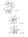
- FIGS. 3-4 disclose an alternate embodiment of carrying mechanism 20, where like numerals refer to like parts. Persons skilled in the art should recognize that all the lessons taught by the previous embodiment are incorporated into the present embodiment by reference.
- miter saw 10 has at least one front foot 11FF and at least one rear foot 11 RF. Each foot preferably has at least one opening 11FO defined by a wall 11FW.
- Plugs 21 may be inserted through openings 11FO.
- Plugs 21 are preferably made of plastic, such as nylon, rubber, etc.
- Plugs 21 are preferably shaped as a truncated cone. Alternatively, plugs 21 are substantially cylindrical. However, persons skilled in the art will recognize that plugs 21 can be shaped into any shape necessary to engage openings 11 FO.
- the user can push plugs 21' through openings 11FO from the underside of base 11, screw on the eyelets 22, attach belt 24 to eyelets 22, and carry the miter saw 10.
- the user can push plugs 21" through openings 11FO from the top of base 11, screw on the eyelets 22, attach belt 24 to eyelets 22, and carry the miter saw 10.
- Plug 21" may have split ends 21E which expand as eyelet 22 is screwed thereon to maintain plug 21" within opening 11FO.
- openings 11 FO are preferably disposed on both front and rear feet 11FF, 11RF of base 11.
- openings 11FO may be disposed on the same foot.
- belt 24 may be attached to only one eyelet 22.
Landscapes
- Engineering & Computer Science (AREA)
- Mechanical Engineering (AREA)
- Sawing (AREA)
- Automatic Tool Replacement In Machine Tools (AREA)
- Portable Nailing Machines And Staplers (AREA)
- Portable Power Tools In General (AREA)
- Electrical Discharge Machining, Electrochemical Machining, And Combined Machining (AREA)
- Yarns And Mechanical Finishing Of Yarns Or Ropes (AREA)
Abstract
Description
- This invention relates generally to in general to power tools, and, in particular to a power tool with a carrying mechanism.
- Typically, power tools are carried by a carrying handle. Sometimes, the power tools may weigh too much for carrying it comfortably by the carrying handle. Accordingly, it is an object of the invention to provide an improved carrying mechanism.
- In accordance with the present invention, an improved power tool is employed. The power tool includes a motor, a housing having first and second holes, first and second plugs disposed within the first and second holes, respectively, the first and second plugs each connectable to a belt. One of the first plug and the belt has a hole and the other of the first plug and the belt has a hook insertable into the hole.
- Additional features and benefits of the present invention are described, and will be apparent from, the accompanying drawings and the detailed description below.
- The accompanying drawings illustrate preferred embodiments of the invention according to the practical application of the principles thereof, and in which:
- FIG. 1 is a front view of a miter saw having a first embodiment of a carrying mechanism constructed with the principles of the invention;
- FIG. 2 is a partial cross-section of the portion circled by line II in FIG. 1;
- FIG. 3 is a partial top plan view of a second embodiment of the carrying mechanism according to the invention; and
- FIG. 4 is a partial cross-sectional view along line IV-IV of FIG. 3, where FIGS. 4A-4B show two alternate arrangements, respectively.
- The invention is now described with reference to the accompanying figures, wherein like numerals designate like parts. Persons skilled in the art shall recognize that while a miter saw has been used to illustrate the invention, the invention can be used in other power tools.
- Miter saws designed for cutting a workpiece are well known in the art. Referring to FIGS. 1-2, a
miter saw 10 typically has abase 11, which may include a rotatable table 12 rotatably attached tobase 11. Apivot arm 14 is pivotally attached to atrunnion 18 to allow a chopping function. Thetrunnion 18 in turn may be pivotally attached to thebase 11 and/or table 12, to allow thetrunnion 18 andpivot arm 14 to pivot relative to thebase 11. - The
pivot arm 14 carries a saw assembly which includesmotor housing 20H, amotor 20M disposed inmotor housing 20H, ablade 17 driven bymotor 20M, anupper blade guard 15 covering an upper part of theblade 17, and alower blade guard 16 pivotally attached toupper blade guard 15 for covering a lower part of theblade 17. - A
fence assembly 19 may be provided on both sides ofblade 17. Persons skilled in the art are referred to the fence assemblies disclosed in US Patent Nos. 5,297,463 and 5,733,148, which are wholly incorporated herein by reference.Fence assembly 19 has a fixedfence 19F disposed onbase 11, and amovable fence 19M slidably disposed on fixedfence 19F. - Miter saw 10 may be provided with
carrying mechanism 20.Base 11 may have openings 110. Persons skilled in the art will recognize that, while openings 11O have been disposed onbase 11, such openings may be disposed in any other part ofmiter saw 10. -
Plugs 21 may be inserted through openings 110.Plugs 21 are preferably made of plastic, such as nylon, rubber, etc. -
Plugs 21 are preferably shaped as a truncated cone. However, persons skilled in the art will recognize thatplugs 21 can be shaped into any shape necessary to engage openings 110. - An
eyelet 22 defining ahole 22H may be screwed untoplug 21. Nevertheless, persons skilled in the art should recognize thateyelet 22 can be attached toplug 21 in other ways as well. In addition,hole 22H could be formed untoplug 21 itself. - A
belt 24 can be attached toeyelets 22 viahooks 23 disposed at each end ofbelt 24. Preferably,belt 24 is made of nylon.Hooks 23 are preferably self-closing hooks. - With such construction, the user can push
plugs 21 through openings 11O, screw on theeyelets 22,attach belt 24 toeyelets 22, and carry the miter saw 10. Preferably, openings 11O will be disposed on both left and right sides ofbase 11. However, persons skilled in the art should recognize that openings 11O may be disposed on the same side ofbase 11. Furthermore, persons skilled in the art should recognize thatbelt 24 may be attached to only oneeyelet 22. - FIGS. 3-4 disclose an alternate embodiment of
carrying mechanism 20, where like numerals refer to like parts. Persons skilled in the art should recognize that all the lessons taught by the previous embodiment are incorporated into the present embodiment by reference. - The main difference between the present and previous embodiments is that, instead of attaching
plugs 21 to a side wall ofbase 11,plugs 21 are attached to feet portions ofbase 11. In particular, miter saw 10 has at least one front foot 11FF and at least onerear foot 11 RF. Each foot preferably has at least one opening 11FO defined by a wall 11FW. -
Plugs 21 may be inserted through openings 11FO.Plugs 21 are preferably made of plastic, such as nylon, rubber, etc.Plugs 21 are preferably shaped as a truncated cone. Alternatively,plugs 21 are substantially cylindrical. However, persons skilled in the art will recognize thatplugs 21 can be shaped into any shape necessary to engageopenings 11 FO. - Referring to FIG. 4A, the user can push plugs 21' through openings 11FO from the underside of
base 11, screw on theeyelets 22,attach belt 24 toeyelets 22, and carry the miter saw 10. Alternatively, referring to FIG. 4B, the user can pushplugs 21" through openings 11FO from the top ofbase 11, screw on theeyelets 22,attach belt 24 toeyelets 22, and carry the miter saw 10.Plug 21" may have split ends 21E which expand aseyelet 22 is screwed thereon to maintainplug 21" within opening 11FO. - As mentioned above,
openings 11 FO are preferably disposed on both front and rear feet 11FF, 11RF ofbase 11. However, persons skilled in the art should recognize that openings 11FO may be disposed on the same foot. Furthermore, persons skilled in the art should recognize thatbelt 24 may be attached to only oneeyelet 22. - Persons skilled in the art may recognize other additions or alternatives to the means disclosed herein. However, all these additions and/or alterations are considered to be equivalents of the present invention.
Claims (20)
- A power tool comprising:a motor;a housing having a first opening;a first plug disposed within the first opening; anda belt attached to the first plug.
- The power tool of Claim 1, wherein one of the first plug and the belt has a first hole and the other of the first plug and the belt has a first hook attachable to the first hole.
- The power tool of Claim 2, wherein the first hook is a self-closing hook.
- The power tool of Claim 2, wherein the first hole is disposed in an eyelet of the first plug, and the belt is connected to the first hook.
- The power tool of Claim 1, wherein the housing has a second opening, the power tool further comprising a second plug disposed within the second opening, wherein the belt is attached to the second plug.
- The power tool of Claim 5, wherein one of the second plug and the belt has a second hole and the other of the second plug and the belt has a second hook attachable to the second hole.
- The power tool of Claim 6, wherein the second hook is a self-closing hook.
- The power tool of Claim 6, wherein the second hole is disposed in an eyelet of the second plug, and the belt is connected to the second hook.
- The power tool of Claim 5, wherein the second plug is a truncated cone.
- The power tool of Claim 5, wherein the second plug is substantially cylindrical.
- The power tool of Claim 5, wherein the second plug is made of plastic.
- The power tool of Claim 5, wherein the housing has front and rear feet.
- The power tool of Claim 12, wherein the first and second plugs are disposed within the front and rear feet, respectively.
- The power tool of Claim 5, wherein the housing has left and right sides.
- The power tool of Claim 14, wherein the first and second plugs are disposed within the left and right sides, respectively.
- The power tool of Claim 1, wherein the first plug is a truncated cone.
- The power tool of Claim 1, wherein the first plug is substantially cylindrical.
- The power tool of Claim 1, wherein the first plug is made of plastic.
- The power tool of Claim 1, wherein the motor drives a blade.
- The power tool of Claim 1, wherein the power tool is a miter saw.
Applications Claiming Priority (2)
| Application Number | Priority Date | Filing Date | Title |
|---|---|---|---|
| US226010 | 2002-08-22 | ||
| US10/226,010 US6732627B2 (en) | 2002-08-22 | 2002-08-22 | Carrying mechanism for power tools |
Publications (2)
| Publication Number | Publication Date |
|---|---|
| EP1403009A1 true EP1403009A1 (en) | 2004-03-31 |
| EP1403009B1 EP1403009B1 (en) | 2008-12-10 |
Family
ID=31887136
Family Applications (1)
| Application Number | Title | Priority Date | Filing Date |
|---|---|---|---|
| EP03018542A Expired - Lifetime EP1403009B1 (en) | 2002-08-22 | 2003-08-18 | Carrying Mechanism for Power Tools |
Country Status (4)
| Country | Link |
|---|---|
| US (1) | US6732627B2 (en) |
| EP (1) | EP1403009B1 (en) |
| AT (1) | ATE416892T1 (en) |
| DE (1) | DE60325149D1 (en) |
Cited By (2)
| Publication number | Priority date | Publication date | Assignee | Title |
|---|---|---|---|---|
| DE102007035295A1 (en) * | 2007-07-27 | 2009-01-29 | Rainer Nowak | Heavy device i.e. brush cutter, mounting apparatus, has water-soluble pellet inserted into guide of bolts, so that bolts are held against spring force in locking position, and guide outwardly opened, so that fluid reaches pellet |
| CN110976953A (en) * | 2019-12-16 | 2020-04-10 | 北京龙威发电技术有限公司 | Narrow space axial pinhole processingequipment |
Families Citing this family (13)
| Publication number | Priority date | Publication date | Assignee | Title |
|---|---|---|---|---|
| US20020117531A1 (en) * | 2001-02-07 | 2002-08-29 | Schell Craig A. | Fastener tool |
| US6835032B1 (en) * | 2003-09-05 | 2004-12-28 | Credo Technology Corporation | Rotary power hand tool having a flexible handle and attachment system |
| US20060091168A1 (en) * | 2004-10-29 | 2006-05-04 | Ng Koon Y | Belt clip for hand-held power tool |
| US7942299B2 (en) * | 2006-05-31 | 2011-05-17 | Black & Decker Inc. | Hand tool with belt or rafter hook |
| EP2370238B1 (en) * | 2008-12-30 | 2015-07-01 | Husqvarna AB | Portable hand-held power tool |
| US10882123B2 (en) | 2015-02-25 | 2021-01-05 | Milwaukee Electric Tool Corporation | Miter saw |
| EP3520975B1 (en) * | 2018-02-06 | 2022-01-05 | Andreas Stihl AG & Co. KG | Garden and/or forest system |
| US11691194B2 (en) * | 2020-05-04 | 2023-07-04 | The Boeing Company | Ergonomic riveting tool system |
| USD1024557S1 (en) | 2022-06-08 | 2024-04-30 | Yeti Coolers, Llc | Container |
| US11912477B2 (en) | 2022-06-08 | 2024-02-27 | Yeti Coolers, Llc | Container with handle and latching system |
| USD1063376S1 (en) | 2022-06-08 | 2025-02-25 | Yeti Coolers, Llc | Container |
| USD1036116S1 (en) | 2022-06-08 | 2024-07-23 | Yeti Coolers, Llc | Container |
| USD1036119S1 (en) | 2022-11-30 | 2024-07-23 | Yeti Coolers, Llc | Container |
Citations (5)
| Publication number | Priority date | Publication date | Assignee | Title |
|---|---|---|---|---|
| US3115910A (en) * | 1961-06-23 | 1963-12-31 | Ezekiel C Steiner | Scribe saws |
| US4413412A (en) * | 1980-08-01 | 1983-11-08 | Firma Schmid & Wezel | Motor-driven scraping tool |
| FR2589339A1 (en) * | 1985-11-04 | 1987-05-07 | Michel Jean Louis | Cover for storage and transportation of motor chain-saws |
| DE10042178C1 (en) * | 2000-08-28 | 2001-12-20 | Hilti Ag | Hand-operated electric tool, e.g. electric drill or hammer-drill, has safety cord for preventing tool dropping onto worker below |
| DE10102290A1 (en) * | 2001-01-09 | 2002-07-18 | Thomas Engert | Wall plug comprises split cylindrical sleeve spread by conical plug with spring at top which can be locked in place by cap |
Family Cites Families (12)
| Publication number | Priority date | Publication date | Assignee | Title |
|---|---|---|---|---|
| US3790049A (en) * | 1972-05-08 | 1974-02-05 | A Bohanec | Adjustable carrying strap |
| US3823474A (en) * | 1973-05-02 | 1974-07-16 | Inst Cercetari Si Proiectari P | Carrying frame for power saw |
| US4659129A (en) * | 1986-02-26 | 1987-04-21 | Schuetzeberg Roy L | Ski carrier with lock |
| SE460270B (en) * | 1986-11-06 | 1989-09-25 | Electrolux Ab | DEVICE IN ENGINE-DRIVEN EQUIPMENT |
| US4748712A (en) * | 1987-02-24 | 1988-06-07 | Digiovanni Judith | Cobweb vacuum cleaner |
| US4934233B1 (en) * | 1988-06-29 | 1994-08-23 | Emerson Electric Co | Compound miter saw |
| US5353465A (en) * | 1992-09-30 | 1994-10-11 | Webster Pierce | Scraper apparatus |
| DE19502171C2 (en) * | 1995-01-25 | 2003-12-18 | Stihl Maschf Andreas | Hand-held implement |
| US5615746A (en) * | 1996-02-02 | 1997-04-01 | Chu; George | Reinforced pneumatic tool holder |
| US6070676A (en) * | 1998-08-13 | 2000-06-06 | Framatome Connectors International | Dual location handle and trigger for a hand-held power tool |
| DE19856266A1 (en) * | 1998-12-07 | 2000-06-08 | Hilti Ag | Electrically operated handheld device |
| US6446734B1 (en) * | 1999-11-11 | 2002-09-10 | Black & Decker Inc. | Motor/handle housing and gear case mounting for portable power tool |
-
2002
- 2002-08-22 US US10/226,010 patent/US6732627B2/en not_active Expired - Fee Related
-
2003
- 2003-08-18 EP EP03018542A patent/EP1403009B1/en not_active Expired - Lifetime
- 2003-08-18 AT AT03018542T patent/ATE416892T1/en not_active IP Right Cessation
- 2003-08-18 DE DE60325149T patent/DE60325149D1/en not_active Expired - Lifetime
Patent Citations (5)
| Publication number | Priority date | Publication date | Assignee | Title |
|---|---|---|---|---|
| US3115910A (en) * | 1961-06-23 | 1963-12-31 | Ezekiel C Steiner | Scribe saws |
| US4413412A (en) * | 1980-08-01 | 1983-11-08 | Firma Schmid & Wezel | Motor-driven scraping tool |
| FR2589339A1 (en) * | 1985-11-04 | 1987-05-07 | Michel Jean Louis | Cover for storage and transportation of motor chain-saws |
| DE10042178C1 (en) * | 2000-08-28 | 2001-12-20 | Hilti Ag | Hand-operated electric tool, e.g. electric drill or hammer-drill, has safety cord for preventing tool dropping onto worker below |
| DE10102290A1 (en) * | 2001-01-09 | 2002-07-18 | Thomas Engert | Wall plug comprises split cylindrical sleeve spread by conical plug with spring at top which can be locked in place by cap |
Cited By (2)
| Publication number | Priority date | Publication date | Assignee | Title |
|---|---|---|---|---|
| DE102007035295A1 (en) * | 2007-07-27 | 2009-01-29 | Rainer Nowak | Heavy device i.e. brush cutter, mounting apparatus, has water-soluble pellet inserted into guide of bolts, so that bolts are held against spring force in locking position, and guide outwardly opened, so that fluid reaches pellet |
| CN110976953A (en) * | 2019-12-16 | 2020-04-10 | 北京龙威发电技术有限公司 | Narrow space axial pinhole processingequipment |
Also Published As
| Publication number | Publication date |
|---|---|
| ATE416892T1 (en) | 2008-12-15 |
| US6732627B2 (en) | 2004-05-11 |
| EP1403009B1 (en) | 2008-12-10 |
| DE60325149D1 (en) | 2009-01-22 |
| US20040035596A1 (en) | 2004-02-26 |
Similar Documents
| Publication | Publication Date | Title |
|---|---|---|
| EP1403009B1 (en) | Carrying Mechanism for Power Tools | |
| US8286359B2 (en) | Battery operated chain saw | |
| US6575590B1 (en) | Light system for battery powered drill | |
| CA2211988C (en) | Depth-of-cut mechanism for circular saw | |
| EP3741486B1 (en) | Blade guard assembly | |
| US6470576B2 (en) | Battery powered circular saw | |
| USD492412S1 (en) | Surgical saw blade | |
| USD429987S (en) | Multi-purpose tool | |
| EP2404692A1 (en) | Portable cutting machine | |
| CA2404512A1 (en) | Rotating tool drive unit for food processing apparatus, and food processing apparatus equipped with same | |
| USD485140S1 (en) | Reciprocating saw blade | |
| US10888987B2 (en) | Power tool ski system and method | |
| US11167442B2 (en) | Miter saw with improved carrying mode | |
| USD484759S1 (en) | Reciprocating saw blade | |
| USD485479S1 (en) | Reciprocating saw blade | |
| EP1448333A1 (en) | Electrical working machine | |
| USD485141S1 (en) | Reciprocating saw blade | |
| JP4545848B2 (en) | Battery operated circular saw tool | |
| US7174641B2 (en) | Cutting tool | |
| US5870827A (en) | Sawblade and stabilizing handle attachments for a power drill | |
| EP1941976A1 (en) | A rotary power and tool having a flexible handle and attachment system | |
| US20070062048A1 (en) | Observation device for portable circular saws | |
| EP1516698B1 (en) | Drill press | |
| JP2002172568A (en) | Motor-driven tool | |
| JP2565090Y2 (en) | Saw sheath |
Legal Events
| Date | Code | Title | Description |
|---|---|---|---|
| PUAI | Public reference made under article 153(3) epc to a published international application that has entered the european phase |
Free format text: ORIGINAL CODE: 0009012 |
|
| AK | Designated contracting states |
Kind code of ref document: A1 Designated state(s): AT BE BG CH CY CZ DE DK EE ES FI FR GB GR HU IE IT LI LU MC NL PT RO SE SI SK TR |
|
| AX | Request for extension of the european patent |
Extension state: AL LT LV MK |
|
| 17P | Request for examination filed |
Effective date: 20040514 |
|
| AKX | Designation fees paid |
Designated state(s): AT BE BG CH CY CZ DE DK EE ES FI FR GB GR HU IE IT LI LU MC NL PT RO SE SI SK TR |
|
| R17C | First examination report despatched (corrected) |
Effective date: 20070626 |
|
| GRAP | Despatch of communication of intention to grant a patent |
Free format text: ORIGINAL CODE: EPIDOSNIGR1 |
|
| GRAS | Grant fee paid |
Free format text: ORIGINAL CODE: EPIDOSNIGR3 |
|
| GRAS | Grant fee paid |
Free format text: ORIGINAL CODE: EPIDOSNIGR3 |
|
| GRAA | (expected) grant |
Free format text: ORIGINAL CODE: 0009210 |
|
| AK | Designated contracting states |
Kind code of ref document: B1 Designated state(s): AT BE BG CH CY CZ DE DK EE ES FI FR GB GR HU IE IT LI LU MC NL PT RO SE SI SK TR |
|
| REG | Reference to a national code |
Ref country code: GB Ref legal event code: FG4D |
|
| REG | Reference to a national code |
Ref country code: CH Ref legal event code: EP |
|
| REG | Reference to a national code |
Ref country code: IE Ref legal event code: FG4D |
|
| REF | Corresponds to: |
Ref document number: 60325149 Country of ref document: DE Date of ref document: 20090122 Kind code of ref document: P |
|
| PG25 | Lapsed in a contracting state [announced via postgrant information from national office to epo] |
Ref country code: SI Free format text: LAPSE BECAUSE OF FAILURE TO SUBMIT A TRANSLATION OF THE DESCRIPTION OR TO PAY THE FEE WITHIN THE PRESCRIBED TIME-LIMIT Effective date: 20081210 Ref country code: FI Free format text: LAPSE BECAUSE OF FAILURE TO SUBMIT A TRANSLATION OF THE DESCRIPTION OR TO PAY THE FEE WITHIN THE PRESCRIBED TIME-LIMIT Effective date: 20081210 Ref country code: NL Free format text: LAPSE BECAUSE OF FAILURE TO SUBMIT A TRANSLATION OF THE DESCRIPTION OR TO PAY THE FEE WITHIN THE PRESCRIBED TIME-LIMIT Effective date: 20081210 |
|
| NLV1 | Nl: lapsed or annulled due to failure to fulfill the requirements of art. 29p and 29m of the patents act | ||
| PG25 | Lapsed in a contracting state [announced via postgrant information from national office to epo] |
Ref country code: BE Free format text: LAPSE BECAUSE OF FAILURE TO SUBMIT A TRANSLATION OF THE DESCRIPTION OR TO PAY THE FEE WITHIN THE PRESCRIBED TIME-LIMIT Effective date: 20081210 Ref country code: ES Free format text: LAPSE BECAUSE OF FAILURE TO SUBMIT A TRANSLATION OF THE DESCRIPTION OR TO PAY THE FEE WITHIN THE PRESCRIBED TIME-LIMIT Effective date: 20090321 Ref country code: EE Free format text: LAPSE BECAUSE OF FAILURE TO SUBMIT A TRANSLATION OF THE DESCRIPTION OR TO PAY THE FEE WITHIN THE PRESCRIBED TIME-LIMIT Effective date: 20081210 Ref country code: BG Free format text: LAPSE BECAUSE OF FAILURE TO SUBMIT A TRANSLATION OF THE DESCRIPTION OR TO PAY THE FEE WITHIN THE PRESCRIBED TIME-LIMIT Effective date: 20090310 Ref country code: RO Free format text: LAPSE BECAUSE OF FAILURE TO SUBMIT A TRANSLATION OF THE DESCRIPTION OR TO PAY THE FEE WITHIN THE PRESCRIBED TIME-LIMIT Effective date: 20081210 |
|
| PG25 | Lapsed in a contracting state [announced via postgrant information from national office to epo] |
Ref country code: CZ Free format text: LAPSE BECAUSE OF FAILURE TO SUBMIT A TRANSLATION OF THE DESCRIPTION OR TO PAY THE FEE WITHIN THE PRESCRIBED TIME-LIMIT Effective date: 20081210 Ref country code: SE Free format text: LAPSE BECAUSE OF FAILURE TO SUBMIT A TRANSLATION OF THE DESCRIPTION OR TO PAY THE FEE WITHIN THE PRESCRIBED TIME-LIMIT Effective date: 20090310 Ref country code: PT Free format text: LAPSE BECAUSE OF FAILURE TO SUBMIT A TRANSLATION OF THE DESCRIPTION OR TO PAY THE FEE WITHIN THE PRESCRIBED TIME-LIMIT Effective date: 20090511 Ref country code: AT Free format text: LAPSE BECAUSE OF FAILURE TO SUBMIT A TRANSLATION OF THE DESCRIPTION OR TO PAY THE FEE WITHIN THE PRESCRIBED TIME-LIMIT Effective date: 20081210 |
|
| PG25 | Lapsed in a contracting state [announced via postgrant information from national office to epo] |
Ref country code: SK Free format text: LAPSE BECAUSE OF FAILURE TO SUBMIT A TRANSLATION OF THE DESCRIPTION OR TO PAY THE FEE WITHIN THE PRESCRIBED TIME-LIMIT Effective date: 20081210 |
|
| PLBE | No opposition filed within time limit |
Free format text: ORIGINAL CODE: 0009261 |
|
| STAA | Information on the status of an ep patent application or granted ep patent |
Free format text: STATUS: NO OPPOSITION FILED WITHIN TIME LIMIT |
|
| PG25 | Lapsed in a contracting state [announced via postgrant information from national office to epo] |
Ref country code: DK Free format text: LAPSE BECAUSE OF FAILURE TO SUBMIT A TRANSLATION OF THE DESCRIPTION OR TO PAY THE FEE WITHIN THE PRESCRIBED TIME-LIMIT Effective date: 20081210 |
|
| 26N | No opposition filed |
Effective date: 20090911 |
|
| PG25 | Lapsed in a contracting state [announced via postgrant information from national office to epo] |
Ref country code: MC Free format text: LAPSE BECAUSE OF NON-PAYMENT OF DUE FEES Effective date: 20090831 |
|
| REG | Reference to a national code |
Ref country code: CH Ref legal event code: PL |
|
| PG25 | Lapsed in a contracting state [announced via postgrant information from national office to epo] |
Ref country code: CH Free format text: LAPSE BECAUSE OF NON-PAYMENT OF DUE FEES Effective date: 20090831 Ref country code: LI Free format text: LAPSE BECAUSE OF NON-PAYMENT OF DUE FEES Effective date: 20090831 |
|
| REG | Reference to a national code |
Ref country code: FR Ref legal event code: ST Effective date: 20100430 |
|
| REG | Reference to a national code |
Ref country code: IE Ref legal event code: MM4A |
|
| PG25 | Lapsed in a contracting state [announced via postgrant information from national office to epo] |
Ref country code: FR Free format text: LAPSE BECAUSE OF NON-PAYMENT OF DUE FEES Effective date: 20090831 Ref country code: IE Free format text: LAPSE BECAUSE OF NON-PAYMENT OF DUE FEES Effective date: 20090818 |
|
| PG25 | Lapsed in a contracting state [announced via postgrant information from national office to epo] |
Ref country code: GR Free format text: LAPSE BECAUSE OF FAILURE TO SUBMIT A TRANSLATION OF THE DESCRIPTION OR TO PAY THE FEE WITHIN THE PRESCRIBED TIME-LIMIT Effective date: 20090311 |
|
| PG25 | Lapsed in a contracting state [announced via postgrant information from national office to epo] |
Ref country code: IT Free format text: LAPSE BECAUSE OF FAILURE TO SUBMIT A TRANSLATION OF THE DESCRIPTION OR TO PAY THE FEE WITHIN THE PRESCRIBED TIME-LIMIT Effective date: 20081210 |
|
| PG25 | Lapsed in a contracting state [announced via postgrant information from national office to epo] |
Ref country code: LU Free format text: LAPSE BECAUSE OF NON-PAYMENT OF DUE FEES Effective date: 20090818 |
|
| PG25 | Lapsed in a contracting state [announced via postgrant information from national office to epo] |
Ref country code: HU Free format text: LAPSE BECAUSE OF FAILURE TO SUBMIT A TRANSLATION OF THE DESCRIPTION OR TO PAY THE FEE WITHIN THE PRESCRIBED TIME-LIMIT Effective date: 20090611 |
|
| PG25 | Lapsed in a contracting state [announced via postgrant information from national office to epo] |
Ref country code: TR Free format text: LAPSE BECAUSE OF FAILURE TO SUBMIT A TRANSLATION OF THE DESCRIPTION OR TO PAY THE FEE WITHIN THE PRESCRIBED TIME-LIMIT Effective date: 20081210 |
|
| PG25 | Lapsed in a contracting state [announced via postgrant information from national office to epo] |
Ref country code: CY Free format text: LAPSE BECAUSE OF FAILURE TO SUBMIT A TRANSLATION OF THE DESCRIPTION OR TO PAY THE FEE WITHIN THE PRESCRIBED TIME-LIMIT Effective date: 20081210 |
|
| PGFP | Annual fee paid to national office [announced via postgrant information from national office to epo] |
Ref country code: DE Payment date: 20140827 Year of fee payment: 12 |
|
| PGFP | Annual fee paid to national office [announced via postgrant information from national office to epo] |
Ref country code: GB Payment date: 20140827 Year of fee payment: 12 |
|
| REG | Reference to a national code |
Ref country code: DE Ref legal event code: R119 Ref document number: 60325149 Country of ref document: DE |
|
| GBPC | Gb: european patent ceased through non-payment of renewal fee |
Effective date: 20150818 |
|
| PG25 | Lapsed in a contracting state [announced via postgrant information from national office to epo] |
Ref country code: DE Free format text: LAPSE BECAUSE OF NON-PAYMENT OF DUE FEES Effective date: 20160301 Ref country code: GB Free format text: LAPSE BECAUSE OF NON-PAYMENT OF DUE FEES Effective date: 20150818 |