EP1401235A1 - Brasseur optique d'architecture multigranulaire - Google Patents
Brasseur optique d'architecture multigranulaire Download PDFInfo
- Publication number
- EP1401235A1 EP1401235A1 EP03291877A EP03291877A EP1401235A1 EP 1401235 A1 EP1401235 A1 EP 1401235A1 EP 03291877 A EP03291877 A EP 03291877A EP 03291877 A EP03291877 A EP 03291877A EP 1401235 A1 EP1401235 A1 EP 1401235A1
- Authority
- EP
- European Patent Office
- Prior art keywords
- matrix
- ports
- optical
- sub
- output
- Prior art date
- Legal status (The legal status is an assumption and is not a legal conclusion. Google has not performed a legal analysis and makes no representation as to the accuracy of the status listed.)
- Granted
Links
- 230000003287 optical effect Effects 0.000 title claims abstract description 92
- 239000011159 matrix material Substances 0.000 claims abstract description 101
- 238000004891 communication Methods 0.000 claims description 40
- 238000003780 insertion Methods 0.000 claims description 9
- 230000037431 insertion Effects 0.000 claims description 9
- 238000000605 extraction Methods 0.000 claims description 8
- 238000006243 chemical reaction Methods 0.000 claims description 6
- 230000008878 coupling Effects 0.000 claims description 6
- 238000010168 coupling process Methods 0.000 claims description 6
- 238000005859 coupling reaction Methods 0.000 claims description 6
- 239000000835 fiber Substances 0.000 description 16
- 235000021183 entrée Nutrition 0.000 description 11
- 239000002131 composite material Substances 0.000 description 6
- 230000008707 rearrangement Effects 0.000 description 5
- 239000000969 carrier Substances 0.000 description 3
- 239000013307 optical fiber Substances 0.000 description 3
- 238000003199 nucleic acid amplification method Methods 0.000 description 2
- 230000008929 regeneration Effects 0.000 description 2
- 238000011069 regeneration method Methods 0.000 description 2
- 230000003321 amplification Effects 0.000 description 1
- 238000013459 approach Methods 0.000 description 1
- 238000003491 array Methods 0.000 description 1
- 230000005540 biological transmission Effects 0.000 description 1
- 230000000593 degrading effect Effects 0.000 description 1
- 230000009977 dual effect Effects 0.000 description 1
- 238000005516 engineering process Methods 0.000 description 1
- 230000003370 grooming effect Effects 0.000 description 1
- 238000004519 manufacturing process Methods 0.000 description 1
- 238000000034 method Methods 0.000 description 1
- 238000004513 sizing Methods 0.000 description 1
- 238000012546 transfer Methods 0.000 description 1
Images

Classifications
-
- H—ELECTRICITY
- H04—ELECTRIC COMMUNICATION TECHNIQUE
- H04Q—SELECTING
- H04Q11/00—Selecting arrangements for multiplex systems
- H04Q11/0001—Selecting arrangements for multiplex systems using optical switching
- H04Q11/0005—Switch and router aspects
-
- H—ELECTRICITY
- H04—ELECTRIC COMMUNICATION TECHNIQUE
- H04Q—SELECTING
- H04Q11/00—Selecting arrangements for multiplex systems
- H04Q11/0001—Selecting arrangements for multiplex systems using optical switching
- H04Q11/0062—Network aspects
- H04Q2011/0075—Wavelength grouping or hierarchical aspects
Definitions
- the present invention relates to an optical cross-architecture multigranular intended to be used in a communication node of a optical telecommunications network.
- Optical telecommunications networks are intended to carry very significant digital data traffic on continental and intercontinental scales, for example for multimedia applications on the Internet.
- Optical technology currently makes it possible to ensure rates of the order of Tera (10 12 ) bits per second over a fiber, without reaching the theoretical limits which are much higher. It is therefore the solution of the future for the exchange of high density information, especially for voice and video.
- the known optical telecommunications networks using the principle of switching include communication nodes provided fast cross-connects to route groups of carrier optical signals digital data, generally by amplitude modulation of waves optical carriers.
- This multigranular approach increases the capacity of the transmission network while maintaining a reasonable degree of complexity for switching.
- Such a cross-connect includes three optical switching stages: a dedicated wavelength stage, a dedicated wavelength band stage and a dedicated fiber optic stage.
- Each floor uses a matrix of optical switching which has the function of orienting groups of signals digital optics by means of a set of ports respectively input and output ports.
- the wavelength band optical switching matrix includes first input ports which each have the function of receive digital optical signals grouped in the same band wavelengths and coming from the dedicated fiber optic stage. so too this matrix includes first output ports which each serve to deliver optical signals grouped in the same length band wave for the dedicated fiber optic stage.
- This wavelength band optical switching matrix comprises, in one of the embodiments presented, second output ports which are connected to the first input ports of the matrix optical wavelength switching via means of wavelength demultiplexing.
- this matrix includes second input ports which are connected to first output ports of the optical wavelength switching matrix via means of wavelength multiplexing.
- the length band switching matrix wave includes third input ports capable of receiving bands wavelengths emitted by a local network connected to the communication node communication associated with the brewer as well as the third output ports capable of transmitting wavelength bands to this local network.
- the wavelength switching matrix also includes this type input ports and output ports.
- optical band switching matrices of lengths wavelength and wavelength have a large number of ports input and output ports, which increases their manufacturing cost while like the cost of their interfaces.
- the present invention aims to provide an optical cross-connect of multigranular architecture having at least one switching stage in wavelength and a wavelength band switching stage, inexpensive and suitable for all types of traffic and preferably suitable for rearrangements between separate bands.
- said series of firsts sub matrices includes n first sub matrices, each dedicated to one distinct from said n wavelength bands and comprising p said input switch ports and p of said output switch ports, and at least two of the first sub-matrices, called redirection, each include at least one distinct of said redirect ports input and at least one separate from said output redirect ports and are each coupled to one distinct from the second sub-matrices.
- each redirection sub-matrix is associated with a second under predetermined matrix. This allows for example rearrangements between bands of identical wavelengths but transmitted by separate fibers.
- At least two of the second sub-matrices each include at least one inter matrix communication port input and at least one communication port between output matrix, each communication port between input matrix being able to receive a signal carrying information from one of said second sub-matrices and each communication port between the output matrix being capable of delivering a signal carrying information intended for one of said second sub matrices.
- the signal carrying information can be optical or electrical, digital or analog depending on the nature of the second sub-matrices and according to their interfaces.
- Communication ports between input and output matrix convert one or more wavelengths of a band into another band and therefore rearrange the information between bands, by example to fill a partially unoccupied strip.
- the brewer may include a means of switching said inter matrix coupling all the ports of inter input matrix communication with all of the inter output matrix communication.
- the carrier signals information is optical and the brewer includes a concentrator optical signal optics coupling all the ports of inter output matrix communication with the inputs of the means of inter matrix switching and an optical deconcentrator of optical signals coupling the outputs of the inter matrix switching means with the assembly communication ports between input matrix.
- the signals information carriers are optical and the inter switching means matrix includes means for wavelength conversion.
- the brewer comprises means of wavelength conversion and preferably type regenerators 3R when said signals are digital, said means being arranged between the output switch ports of the second sub-dies and the wavelength multiplexing means.
- a 3R type regenerator (3R for Retiming, Reshaping, Reamplification in English) provides the length conversion function wave at the same time as the resynchronization, reset form and re-amplification of a digital optical signal.
- optical-electrical converters and electrical-optical converters can be arranged respectively at least at the ports input switch and at least at the output switch ports said second sub-matrices.
- the brewer may include a concentrator optics with inputs connected to a set of output ports, said extraction ports, second sub-matrices, and a deconcentrator optics whose outputs are connected to a set of input ports, so-called insertion ports, second sub-matrices.
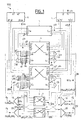
- FIG. 1 schematically represents, in a first mode of preferred embodiment of the invention, an optical stirrer 1000 of signals optics carrying information, for example in the form of data digital, multigranular architecture brewer.
- Each optical signal digital is in the form of a carrier optical wave modulated by example in amplitude.
- Brewer 1000 has a first stage 100 for wavelength band switching and a second stage 200 for wavelength switching.
- the first stage 100 includes an optical switching matrix in wavelength bands, as a series of first two under optical switching arrays 1, 2 arranged in parallel. Each is dedicated to a separate band of wavelengths B1, B2 respectively, which each include for example four wavelengths ⁇ 11, ⁇ 12, ⁇ 13, ⁇ 14 and ⁇ 21, ⁇ 22, ⁇ 23, ⁇ 24 respectively usable for carrying digital data.
- the first sub-matrices, called redirection matrices, 1, 2 include two input switch ports 1a, 1b and 2a, 2b respectively and two outlet switch ports 1'a, 1'b and 2'a, 2'b respectively.
- the number of input referral ports and referral ports output corresponds to the number of input optical fibers Fa, Fb and fibers output optics F'a, F'b connected via demultiplexing means in wavelength bands 10, 20 and multiplexing means in 10 ', 20' wavelength band at these switch ports.
- the invention also applies in the case where a single fiber is involved input and a single output fiber.
- the input fiber (s) and the output fibers can be directly line optical fibers or else bonding fibers in the case where the stirrer 1000 has a stage dedicated fiber, for example analogous to that of the prior art.
- the redirection sub-matrices 1, 2 include two input forwarding ports 11, 12 and 21, 22 respectively and two ports of output redirection 11 ', 12' and 21 ', 22' respectively.
- One and / or the other of the redirected sub-matrices could not have a single input forwarding port and a single forwarding port Release.
- the choice of this sizing depends on the parameters of the network.
- one or more other firsts under optical switching matrices are added and arranged in parallel and do not necessarily have redirection ports.
- one and / or the other of the redirection sub-matrices 1, 2 can have one or more tape insertion ports at the input and, in output, from one or more tape extraction ports (not shown).
- the second stage 200 comprises an optical matrix of wavelength switching, as a series of two second optical sub-matrices 3, 4 respectively coupled to a sub-matrix with separate redirect 1, 2.
- the second sub-matrices 3, 4 comprise two groups of four input switch ports 3a, 3b and 4a, 4b respectively, which are connected to output forwarding ports separate 11 ', 12' and 21 ', 22' respectively by means of wavelength demultiplexing 30, 40 and 50, 60 respectively.
- the second sub-matrices 3, 4 have two groups of four output switch ports 3'a, 3'b and 4'a, 4'b respectively, which are connected to output forwarding ports separate 11, 12 and 21, 22 respectively via demultiplexing means in wavelength 30 ', 40' and 50 ', 60'.
- the second sub-matrices 3, 4 comprise, at the input, two insertion ports of wavelengths 3c, 3d and 4c, 4d respectively.
- the number of insertion ports can be set between one and eight, eight corresponding to the maximum possible number of wavelengths passing through the two redirect ports.
- the second sub-matrices 3, 4 have, at the output, two ports wavelength extraction 3'c, 3'd and 4'c, 4'd respectively.
- All of the insertion ports 3c, 3d, 4c, 4d are connected to the outputs 71 'to 74' of an optical deconcentrator 7 having two inputs 71, 72 connected to a local network (not shown).
- the set of extraction ports 3'c, 3'd, 4'c, 4'd is connected to the inputs 61 to 64 of an optical hub 6 having two outputs 61 ', 62' to a local network (not shown).
- the second sub-matrices 3, 4 have two so-called ports communication between input matrix 31, 32 and 41, 42 respectively and two so-called inter-output communication ports 31 ', 32' and 41 ', 42' respectively.
- the number of inter matrix communication ports can be set between one and eight as needed.
- Each communication port between input matrix of one or the other of the second sub-matrices is capable of receiving an optical signal numeric resulting from one of the second distinct under matrixes 3, 4 of the same that each communication port inter matrix output of one or the other second sub-matrices 3, 4 is capable of delivering an optical signal digital intended for another of said second sub-matrices.
- inter-matrix 5 torque all the communication ports between input matrix 31, 32, 41, 42, connected to its 5th inputs, with all of said communication ports inter output matrix 31 ', 32', 41 ', 42'; connected to its 5s outputs.
- Two groups Pa, Pb of digital optical signals conveyed by the fiber Fa, Fb comprise the same two bands of wavelengths B1, B2.
- the signals of the groups Pa, Pb are demultiplexed by band by the means for demultiplexing in a band of wavelengths 10, 20.
- the signals grouped by band are called composite signals B1a, B2a, B1b, B2b and are symbolized in Figure 1 with reference to their band.
- the composite signals B1a, B2a are routed by the first sub-matrix dedicated to their band 1, 2 respectively and lead to a means for multiplexing in a band of wavelengths 20 ′, 10 ′.
- the composite signal B1 b delivered by the output redirection port 12 ', passes through the wavelength demultiplexing means 40 separating it in two digital optical signals s11, s12 of carrier wavelength distinct ⁇ 11, ⁇ 12. These digital signals s11, s12 are directed to two group 3'b exit switch ports.
- a digital optical signal s14 of carrier wavelength by example equal to ⁇ 14 passes through the optical deconcentrator 7 and is injected in the second sub-matrix 3 via the 3d insertion port and comes out via a 3'b group exit switch port.
- the B2b composite signal delivered by the output redirection port 21 ', crosses the wavelength demultiplexing means 50 separating it in two digital optical signals s21, s24 of carrier wavelength distinct ⁇ 21, ⁇ 24.
- the digital signal s21 delivered by one of the communication ports inter output matrix 41 'of the second sub matrix 4, crosses the means inter matrix 5 optical switch which directs the needle to one of the ports inter input matrix communication 32 of the second sub matrix 3.
- the digital signal s24 is delivered by one of the 4'd extraction ports from the second sub-matrix 4 to the concentrator 6.
- the digital signals s11, s12, s21, s14 each pass through an optical regeneration means of type 3R of the 82 series.
- the signal s21 is converted into an optical signal digital s13 carrying the data but at the wavelength ⁇ 13.
- These signals s11, s12, s13, s14 are multiplexed by the multiplexing means in wavelength 40 'to form a rearranged composite signal B1bm.
- Two groups P'a, P'b of signals are formed by the means of 10 ', 20' wavelength band multiplexing from signals composites B1bm, B2a and B1a respectively.
- the signals optics are analog in which case the 3R regenerators are replaced by simple means of wavelength conversion with possible regeneration.
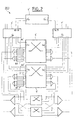
- FIG. 2 schematically represents, in a second mode of preferred embodiment of the invention, an optical 2000 signal mixer digital optics.
- the optical cross-connect 2000 has an optical matrix of commutation, in the form of a series of two second sub matrices 3 ', 4' optics respectively coupled to a redirection sub-matrix separate.
- the other of the second sub-matrices 4 comprises e.g. four 4th input ports and four dual 4s output ports function.
- All the output ports (excluding routing ports) 3s, 4s, are connected to the 6'e inputs of a 6 'optical hub connected at the output to a local network (not shown).
- Two outputs 65, 66, used for the circulation of digital optical signals between sub-matrices, are connected to the inputs of a 5 'inter matrix optical switching means whose two 5's outputs are connected to inputs 75, 76 of a 7 'optical deconcentrator also connected at the input to a local network (not represented).
- All entry ports (excluding referral ports) 3rd, 4th, is connected to the outputs 7's of the optical deconcentrator 7 '.
- the inter matrix 5 ′ optical switching means is provided with wavelength conversion means (not shown) for data rearrangements for example between separate bands.
- FIG. 3 schematically represents, in a third mode of preferred embodiment of the invention, a 3000 optical signal mixer digital in optical and electrical form.
- the optical stirrer 3000 has an electrical matrix of commutation, in the form of a series of two second sub matrices electrical 3 ", 4" respectively coupled to a redirection sub-matrix separate.
- Four series 301, 302, 401, 402 of optical-electrical converters and four series of electrical-optical converters 303, 304, 403, 404 are disposed respectively at the level of the routing ports inlet and at the outlet ports of the second sub 3 "and 4" dies.
- the electrical-optical converters replace the 3R type regenerators.
- Switching means 5 "torque electrical matrix all communication ports between input matrix with all of the inter matrix communication ports second sub-matrices, each inter matrix communication port input capable of receiving a digital electrical signal from the other second under matrix.
- the number of fibers, the number of strips per fiber, the number of wavelengths per band, number of insert ports and ports the number of inter matrix communication ports are chosen as an indication, the dimensioning can be adapted according to the needs (traffic density for example, number of rearrangements to operate etc ).
- the second sub-matrices can as well be of type "black and white "that is to say optical sub-matrices but with interfaces inexpensive whose wavelength is not perfectly fixed and which do not allow the use of the WDM technique within these sub matrices.
- the number of hub output ports and the number of ports of the deconcentrator are chosen according to traffic fluctuations and its average level.
Landscapes
- Engineering & Computer Science (AREA)
- Computer Networks & Wireless Communication (AREA)
- Optical Communication System (AREA)
- Use Of Switch Circuits For Exchanges And Methods Of Control Of Multiplex Exchanges (AREA)
- Light Guides In General And Applications Therefor (AREA)
- Optical Integrated Circuits (AREA)
- Lasers (AREA)
Abstract
Description
- un premier étage pour la commutation en bande de longueurs
d'onde, étage comportant :
- une matrice optique de commutation en bande de longueurs d'onde, dite première matrice, ayant des premiers ports, dits d'aiguillage, d'entrée et des premiers ports, dits d'aiguillage, de sortie ainsi que des deuxièmes ports, dits de redirection, d'entrée et des deuxièmes ports, dits de redirection, de sortie,
- des moyens de démultiplexage en bande de longueurs d'onde ayant p groupe(s) de n sorties associées à n bandes de longueurs d'onde distinctes, chacune des sorties étant connectée à un port d'aiguillage d'entrée distinct de la première matrice,
- des moyens de multiplexage en bande de longueurs d'onde ayant p groupe(s) de n entrées chacune connectée à un port d'aiguillage de sortie distinct de la première matrice,
- un deuxième étage pour la commutation en longueur d'onde, étage
comportant :
- une matrice de commutation en longueur d'onde, dite deuxième matrice, ayant des premiers ports, dits d'aiguillage, d'entrée et des premiers ports, dits d'aiguillage, de sortie,
- des moyens de démultiplexage en longueur d'onde, dont chaque entrée est connectée à un port de redirection de sortie distinct de la première matrice et dont chacune des sorties est connectée à un port d'aiguillage d'entrée distinct de la deuxième matrice,
- des moyens de multiplexage en longueur d'onde, dont chacune des entrées est connectée à un port d'aiguillage de sortie distinct de la deuxième matrice et dont chaque sortie est connectée à un port de redirection d'entrée distinct de la première matrice,
et en ce que la deuxième matrice comporte une série de deuxièmes sous matrices de commutation disposées en parallèle.
- la figure 1 représente schématiquement, dans un premier mode de réalisation préféré de l'invention, un brasseur optique 1000 de signaux optiques numériques,
- la figure 2 représente schématiquement, dans un second mode de réalisation préféré de l'invention, un brasseur optique 2000 de signaux optiques numériques,
- la figure 3 représente schématiquement, dans un troisième mode de réalisation préféré de l'invention, un brasseur optique 3000 de signaux numériques sous forme optique ou électrique.
- quatre ports d'entrée 3e utilisés soit comme des ports d'insertion de longueurs d'onde soit comme des ports de communication inter matrice d'entrée,
- quatre ports de sortie 3s utilisés soit comme des ports d'extraction de longueurs d'onde soit comme des ports de communication inter matrice de sortie.
Claims (9)
- Brasseur optique (1000, 2000, 3000) d'architecture multigranulaire comportant :caractérisé en ce que la première matrice comporte une série de premières sous matrices optiques de commutation disposées en parallèle (1, 2)un premier étage (100) pour la commutation en bande de longueurs d'onde, étage comportant :une matrice optique de commutation en bande de longueurs d'onde, dite première matrice, ayant des premiers ports, dits d'aiguillage, d'entrée (1a à 2b) et des premiers ports, dits d'aiguillage, de sortie (1'a à 2'b) ainsi que des deuxièmes ports, dits de redirection, d'entrée (11 à 22) et des deuxièmes ports, dits de redirection, de sortie (11' à 22'),des moyens de démultiplexage en bande de longueurs d'onde (10, 20) ayant p groupe(s) de n sorties associées à n bandes de longueurs d'onde distinctes, chacune des sorties étant connectée à un port d'aiguillage d'entrée distinct de la première matrice,des moyens de multiplexage en bande de longueurs d'onde (10', 20') ayant p groupe(s) de n entrées chacune connectée à un port d'aiguillage de sortie distinct de la première matrice,un deuxième étage (200) pour la commutation en longueur d'onde, étage comportant :une matrice de commutation en longueur d'onde, dite deuxième matrice, ayant des premiers ports, dits d'aiguillage, d'entrée (3a à 4b) et des premiers ports, dits d'aiguillage, de sortie (3'a à 4'b),des moyens de démultiplexage en longueur d'onde (30 à 60), dont chaque entrée est connectée à un port de redirection de sortie distinct de la première matrice et dont chacune des sorties est connectée à un port d'aiguillage d'entrée distinct de la deuxième matrice,des moyens de multiplexage en longueur d'onde (30' à 60'), dont chacune des entrées est connectée à un port d'aiguillage de sortie distinct de la deuxième matrice et dont chaque sortie est connectée à un port de redirection d'entrée distinct de la première matrice,
et en ce que la deuxième matrice comporte une série de deuxièmes sous matrices de commutation disposées en parallèle (3 à 4"). - Brasseur (1000, 2000, 3000) selon la revendication 1 caractérisé en ce que ladite série de premières sous matrices (1, 2) comprend n premières sous matrices, chacune étant dédiée à l'une distincte desdites n bandes de longueurs d'onde et comprenant p desdits ports d'aiguillage d'entrée et p desdits ports d'aiguillage de sortie, et en ce qu'au moins deux des premières sous matrices, dites à redirection, comprennent chacune au moins l'un distinct desdits ports de redirection d'entrée et au moins l'un distinct desdits ports de redirection de sortie et sont chacune couplées à l'une distincte desdites deuxièmes sous matrices (3 à 4").
- Brasseur (1000, 2000, 3000) selon la revendication 1, caractérisé en ce qu'au moins deux des deuxièmes sous matrices (3 à 4") comprennent chacune au moins un port de communication inter matrice d'entrée (41, 42, 4e) et au moins un port de communication inter matrice de sortie (41', 42', 4s), chaque port de communication inter matrice d'entrée étant apte à recevoir un signal porteur d'informations issu d'une desdites deuxièmes sous matrices et chaque port de communication inter matrice de sortie étant apte à délivrer un signal porteur d'informations destiné à l'une desdites deuxièmes sous-matrices.
- Brasseur (1000, 2000, 3000) selon la revendication 3 caractérisé en ce qu'il comporte un moyen de commutation dit inter matrice (5, 5', 5") couplant l'ensemble desdits ports de communication inter matrice d'entrée avec l'ensemble desdits ports de communication inter matrice de sortie.
- Brasseur (2000) selon la revendication 4 caractérisé en ce que, les signaux porteurs d'informationsétant optiques, le brasseur peut comprendre un concentrateur optique de signaux optiques (6')couplant l'ensemble des ports de communication inter matrice de sortie avec les entrées du moyen de commutation inter matrice (5') et un déconcentrateur optique (7') de signaux optiques couplant les sorties du moyen de commutation inter matrice avec l'ensemble des ports de communication inter matrice d'entrée.
- Brasseur (2000) selon la revendication 4, caractérisé en ce que, les signaux porteurs d'informations étant optiques, le moyen de commutation inter matrice (5') peut comprendre des moyens de conversion en longueur d'onde.
- Brasseur (1000) selon la revendication 1, caractérisé en ce qu'il comprend des moyens de conversion en longueur d'onde et de préférence des régénérateurs de type 3R (81 à 84) lorsque les signaux porteurs d'informations sont optiques et numériques, lesdits moyens étant disposés entre des ports d'aiguillages de sortie de deuxièmes sous matrices (3, 4) et les moyens de multiplexage en longueur d'onde (40 à 60).
- Brasseur (3000) selon la revendication 1, caractérisé en ce que, lesdites deuxièmes sous matrices étant électriques (3", 4"), des convertisseurs optiques-électriques (301 à 402) et des convertisseurs électriques-optiques (303 à 404) sont disposés respectivement au moins au niveau des ports d'aiguillage d'entrée et au moins au niveau des ports d'aiguillage de sortie desdites deuxièmes sous matrices.
- Brasseur (1000) selon la revendication 1, caractérisé en ce qu'il comprend un concentrateur optique (6) dont des entrées (61 à 64) sont connectées à un ensemble de ports de sortie, dits ports d'extraction (3'c à 4'd), desdites deuxièmes sous matrices, et un déconcentrateur optique (7) dont des sorties (71' à 74') sont connectées à un ensemble de ports d'entrée (3c à 4d), dits ports d'insertion, desdites deuxièmes sous matrices.
Applications Claiming Priority (2)
| Application Number | Priority Date | Filing Date | Title |
|---|---|---|---|
| FR0211598A FR2844955B1 (fr) | 2002-09-19 | 2002-09-19 | Brasseur optique d'architecture multigranulaire |
| FR0211598 | 2002-09-19 |
Publications (2)
| Publication Number | Publication Date |
|---|---|
| EP1401235A1 true EP1401235A1 (fr) | 2004-03-24 |
| EP1401235B1 EP1401235B1 (fr) | 2006-06-07 |
Family
ID=31897495
Family Applications (1)
| Application Number | Title | Priority Date | Filing Date |
|---|---|---|---|
| EP03291877A Expired - Lifetime EP1401235B1 (fr) | 2002-09-19 | 2003-07-29 | Brasseur optique d'architecture multigranulaire |
Country Status (5)
| Country | Link |
|---|---|
| US (1) | US20040057726A1 (fr) |
| EP (1) | EP1401235B1 (fr) |
| AT (1) | ATE329473T1 (fr) |
| DE (1) | DE60305822T2 (fr) |
| FR (1) | FR2844955B1 (fr) |
Families Citing this family (3)
| Publication number | Priority date | Publication date | Assignee | Title |
|---|---|---|---|---|
| EP3013066B1 (fr) * | 2013-06-20 | 2019-03-06 | Japan Science and Technology Agency | Répartiteur optique |
| DE102013019643A1 (de) * | 2013-11-22 | 2015-05-28 | Siemens Aktiengesellschaft | Zweistufiger Kreuzschienenverteiler und Verfahren zum Betrieb |
| CN107431551B (zh) * | 2015-04-13 | 2019-02-05 | 华为技术有限公司 | 光交叉互连节点和光信号交换的方法 |
Citations (1)
| Publication number | Priority date | Publication date | Assignee | Title |
|---|---|---|---|---|
| EP1193996A1 (fr) * | 2000-10-02 | 2002-04-03 | Alcatel | Procédé de détection de sous-noeuds de commutation pour la commutation de multiplex à répartition de longueur d'onde |
Family Cites Families (4)
| Publication number | Priority date | Publication date | Assignee | Title |
|---|---|---|---|---|
| IT1255810B (it) * | 1992-08-07 | 1995-11-16 | Alcatel Italia | Rete di connessione fotonica a commutazione di pacchetto per la diffusione d'informazioni |
| EP1162855B1 (fr) * | 2000-06-05 | 2005-12-07 | PIRELLI CAVI E SISTEMI S.p.A. | Réseau optique à multiplexage en longueur d'onde avec une combinaison de routage par longeurs d'onde et de routage de fibres optiques |
| JP3744343B2 (ja) * | 2000-11-08 | 2006-02-08 | 日本電気株式会社 | 光クロスコネクト装置 |
| US7340175B2 (en) * | 2002-01-18 | 2008-03-04 | Nec Corporation | Non-uniform optical waveband aggregator and deaggregator and hierarchical hybrid optical cross-connect system |
-
2002
- 2002-09-19 FR FR0211598A patent/FR2844955B1/fr not_active Expired - Fee Related
-
2003
- 2003-07-29 AT AT03291877T patent/ATE329473T1/de not_active IP Right Cessation
- 2003-07-29 DE DE60305822T patent/DE60305822T2/de not_active Expired - Fee Related
- 2003-07-29 EP EP03291877A patent/EP1401235B1/fr not_active Expired - Lifetime
- 2003-09-17 US US10/663,808 patent/US20040057726A1/en not_active Abandoned
Patent Citations (1)
| Publication number | Priority date | Publication date | Assignee | Title |
|---|---|---|---|---|
| EP1193996A1 (fr) * | 2000-10-02 | 2002-04-03 | Alcatel | Procédé de détection de sous-noeuds de commutation pour la commutation de multiplex à répartition de longueur d'onde |
Non-Patent Citations (4)
| Title |
|---|
| JINNO M ET AL: "ULTRA-WIDE-BAND WDM NETWORKS AND SUPPORTING TECHNOLOGIES", PROCEEDINGS OF THE EUROPEAN CONFERENCE ON NETWORKS AND OPTICAL COMMUNICATIONS 1999. NOC'99. CORE NETWORKS AND NETWORK MANAGEMENT, AMSTERDAM: IOS PRESS, NL, vol. PART 2, 1999, pages 90 - 97, XP000829416, ISBN: 90-5199-497-4 * |
| JUE J P ET AL: "A NEW MODE ARCHITECTURE FOR SCALABLE WDM OPTICAL NETWORKS", ICC '99. 1999 IEEE INTERNATIONAL CONFERENCE ON COMMUNICATIONS. CONFERENCE RECORD. VANCOUVER, CA, JUNE 6 - 10, 1999, IEEE INTERNATIONAL CONFERENCE ON COMMUNICATIONS, NEW YORK, NY: IEEE, US, vol. 3, 6 June 1999 (1999-06-06), pages 1714 - 1718, XP000903663, ISBN: 0-7803-5285-8 * |
| NOIRIE L ET AL: "Multigranularity optical cross-connect", ECOC 2000. 26TH EUROPEAN CONFERENCE ON OPTICAL COMMUNICATION, PROCEEDINGS OF 26TH EUROPEAN CONFERENCE ON OPTICAL COMMUNICATION, MUNICH, GERMANY, 3-7 SEPT. 2000, 2000, Berlin, Germany, VDE Verlag, Germany, pages 269 - 270 vol.3, XP002241353, ISBN: 3-8007-2567-3 * |
| TADA N ET AL: "PHOTONIC TERABITS IP-ROUTERS USING TWO DIMENSIONAL INTERCONNECTION BASED ON MATRIX WDM SCHEME", 25TH EUROPEAN CONFERENCE ON OPTICAL COMMUNICATION. (ECOC'99). NICE, FRANCE, SEPT. 27 - 30, 1999. REGULAR AND INVITED PAPERS, EUROPEAN CONFERENCE ON OPTICAL COMMUNICATION (ECOC), PARIS: SEE, FR, vol. I OF II, 26 September 1999 (1999-09-26), pages I - 450-I-451, XP001035390, ISBN: 2-912328-12-8 * |
Also Published As
| Publication number | Publication date |
|---|---|
| FR2844955A1 (fr) | 2004-03-26 |
| US20040057726A1 (en) | 2004-03-25 |
| EP1401235B1 (fr) | 2006-06-07 |
| FR2844955B1 (fr) | 2005-01-14 |
| ATE329473T1 (de) | 2006-06-15 |
| DE60305822D1 (de) | 2006-07-20 |
| DE60305822T2 (de) | 2007-06-28 |
Similar Documents
| Publication | Publication Date | Title |
|---|---|---|
| JP2989269B2 (ja) | 光ネットワーク用交差接続 | |
| EP2141842B1 (fr) | Dispositif de commutation de signaux optiques | |
| FR2768578A1 (fr) | Reseau d'abonnes a fibres optiques | |
| JPH09511627A (ja) | 光通信ネットワーク | |
| JP2002185482A (ja) | Wdmを用いた透過型フォトニックスロットルーティングによる複合パケットスイッチング方法及びシステム | |
| US20190165877A1 (en) | ENERGY EFFICIENT, CONTENTIONLESS NxM ROADM WITH AMPLIFIED SINGLE WAVELENGTH DROP/ADD PORTS AND CORRESPONDING METHODS | |
| EP0543714A1 (fr) | Repartiteur optique | |
| EP1401235B1 (fr) | Brasseur optique d'architecture multigranulaire | |
| JP3142064B2 (ja) | Atmシステム適合三段スイッチングユニット | |
| FR2933256A1 (fr) | Dispositif de commutation de signaux optiques | |
| EP1349417B1 (fr) | Brasseur de signaux diffusant notamment pour signaux optiques | |
| EP1213945A1 (fr) | Routeur de paquets pour réseau de transmission optique | |
| Hinton | Switching to photonics | |
| EP0720409A1 (fr) | Matrice de commutation photonique | |
| EP1076470B1 (fr) | Sélecteur hybride spatial et spectral et matrice de commutation optique incluant de tels sélecteurs | |
| EP1193995A1 (fr) | Commutateur pour réseau de transmission optique utilisant le multiplexage en longueur d'onde | |
| EP1379100B1 (fr) | Brasseur optique d'architecture multigranulaire | |
| Jin et al. | Optical cross connect based on WDM and space-division multiplexing | |
| EP2160045B1 (fr) | Noeud de commutation de paquets optiques | |
| EP1326474A2 (fr) | Dispositif et procédé de commutation de données optiques pour réseaux de communication optiques | |
| EP1455551A2 (fr) | Module de selection pour commutateur de signaux optiques et commutateur de signaux optiques | |
| EP1289333A1 (fr) | Système de commutation optique tel que brasseur ou routeur pour réseau de transmission | |
| FR2937815A1 (fr) | Dispositif de commutation de signaux optiques | |
| FR2489643A1 (fr) | Concentrateur opto-electronique et autocommutateur-concentrateur opto-electronique de liaisons de telecommunications | |
| Evaldsson et al. | The Concept and Technologies Behind a Metropolitan Optical Network |
Legal Events
| Date | Code | Title | Description |
|---|---|---|---|
| PUAI | Public reference made under article 153(3) epc to a published international application that has entered the european phase |
Free format text: ORIGINAL CODE: 0009012 |
|
| AK | Designated contracting states |
Kind code of ref document: A1 Designated state(s): AT BE BG CH CY CZ DE DK EE ES FI FR GB GR HU IE IT LI LU MC NL PT RO SE SI SK TR |
|
| AX | Request for extension of the european patent |
Extension state: AL LT LV MK |
|
| 17P | Request for examination filed |
Effective date: 20040924 |
|
| AKX | Designation fees paid |
Designated state(s): AT BE BG CH CY CZ DE DK EE ES FI FR GB GR HU IE IT LI LU MC NL PT RO SE SI SK TR |
|
| 17Q | First examination report despatched |
Effective date: 20050127 |
|
| GRAP | Despatch of communication of intention to grant a patent |
Free format text: ORIGINAL CODE: EPIDOSNIGR1 |
|
| GRAS | Grant fee paid |
Free format text: ORIGINAL CODE: EPIDOSNIGR3 |
|
| GRAA | (expected) grant |
Free format text: ORIGINAL CODE: 0009210 |
|
| AK | Designated contracting states |
Kind code of ref document: B1 Designated state(s): AT BE BG CH CY CZ DE DK EE ES FI FR GB GR HU IE IT LI LU MC NL PT RO SE SI SK TR |
|
| PG25 | Lapsed in a contracting state [announced via postgrant information from national office to epo] |
Ref country code: IE Free format text: LAPSE BECAUSE OF FAILURE TO SUBMIT A TRANSLATION OF THE DESCRIPTION OR TO PAY THE FEE WITHIN THE PRESCRIBED TIME-LIMIT Effective date: 20060607 Ref country code: CZ Free format text: LAPSE BECAUSE OF FAILURE TO SUBMIT A TRANSLATION OF THE DESCRIPTION OR TO PAY THE FEE WITHIN THE PRESCRIBED TIME-LIMIT Effective date: 20060607 Ref country code: NL Free format text: LAPSE BECAUSE OF FAILURE TO SUBMIT A TRANSLATION OF THE DESCRIPTION OR TO PAY THE FEE WITHIN THE PRESCRIBED TIME-LIMIT Effective date: 20060607 Ref country code: RO Free format text: LAPSE BECAUSE OF FAILURE TO SUBMIT A TRANSLATION OF THE DESCRIPTION OR TO PAY THE FEE WITHIN THE PRESCRIBED TIME-LIMIT Effective date: 20060607 Ref country code: AT Free format text: LAPSE BECAUSE OF FAILURE TO SUBMIT A TRANSLATION OF THE DESCRIPTION OR TO PAY THE FEE WITHIN THE PRESCRIBED TIME-LIMIT Effective date: 20060607 Ref country code: SK Free format text: LAPSE BECAUSE OF FAILURE TO SUBMIT A TRANSLATION OF THE DESCRIPTION OR TO PAY THE FEE WITHIN THE PRESCRIBED TIME-LIMIT Effective date: 20060607 Ref country code: SI Free format text: LAPSE BECAUSE OF FAILURE TO SUBMIT A TRANSLATION OF THE DESCRIPTION OR TO PAY THE FEE WITHIN THE PRESCRIBED TIME-LIMIT Effective date: 20060607 Ref country code: FI Free format text: LAPSE BECAUSE OF FAILURE TO SUBMIT A TRANSLATION OF THE DESCRIPTION OR TO PAY THE FEE WITHIN THE PRESCRIBED TIME-LIMIT Effective date: 20060607 |
|
| REG | Reference to a national code |
Ref country code: GB Ref legal event code: FG4D Free format text: NOT ENGLISH |
|
| REG | Reference to a national code |
Ref country code: CH Ref legal event code: EP |
|
| REG | Reference to a national code |
Ref country code: IE Ref legal event code: FG4D Free format text: LANGUAGE OF EP DOCUMENT: FRENCH |
|
| PGFP | Annual fee paid to national office [announced via postgrant information from national office to epo] |
Ref country code: DE Payment date: 20060714 Year of fee payment: 4 |
|
| REF | Corresponds to: |
Ref document number: 60305822 Country of ref document: DE Date of ref document: 20060720 Kind code of ref document: P |
|
| PG25 | Lapsed in a contracting state [announced via postgrant information from national office to epo] |
Ref country code: MC Free format text: LAPSE BECAUSE OF NON-PAYMENT OF DUE FEES Effective date: 20060731 Ref country code: BE Free format text: LAPSE BECAUSE OF NON-PAYMENT OF DUE FEES Effective date: 20060731 |
|
| PGFP | Annual fee paid to national office [announced via postgrant information from national office to epo] |
Ref country code: IT Payment date: 20060731 Year of fee payment: 4 |
|
| PG25 | Lapsed in a contracting state [announced via postgrant information from national office to epo] |
Ref country code: DK Free format text: LAPSE BECAUSE OF FAILURE TO SUBMIT A TRANSLATION OF THE DESCRIPTION OR TO PAY THE FEE WITHIN THE PRESCRIBED TIME-LIMIT Effective date: 20060907 Ref country code: SE Free format text: LAPSE BECAUSE OF FAILURE TO SUBMIT A TRANSLATION OF THE DESCRIPTION OR TO PAY THE FEE WITHIN THE PRESCRIBED TIME-LIMIT Effective date: 20060907 |
|
| PG25 | Lapsed in a contracting state [announced via postgrant information from national office to epo] |
Ref country code: ES Free format text: LAPSE BECAUSE OF FAILURE TO SUBMIT A TRANSLATION OF THE DESCRIPTION OR TO PAY THE FEE WITHIN THE PRESCRIBED TIME-LIMIT Effective date: 20060918 |
|
| GBT | Gb: translation of ep patent filed (gb section 77(6)(a)/1977) |
Effective date: 20060912 |
|
| PG25 | Lapsed in a contracting state [announced via postgrant information from national office to epo] |
Ref country code: PT Free format text: LAPSE BECAUSE OF FAILURE TO SUBMIT A TRANSLATION OF THE DESCRIPTION OR TO PAY THE FEE WITHIN THE PRESCRIBED TIME-LIMIT Effective date: 20061107 |
|
| NLV1 | Nl: lapsed or annulled due to failure to fulfill the requirements of art. 29p and 29m of the patents act | ||
| REG | Reference to a national code |
Ref country code: IE Ref legal event code: FD4D |
|
| RAP2 | Party data changed (patent owner data changed or rights of a patent transferred) |
Owner name: ALCATEL LUCENT |
|
| PLBE | No opposition filed within time limit |
Free format text: ORIGINAL CODE: 0009261 |
|
| STAA | Information on the status of an ep patent application or granted ep patent |
Free format text: STATUS: NO OPPOSITION FILED WITHIN TIME LIMIT |
|
| 26N | No opposition filed |
Effective date: 20070308 |
|
| REG | Reference to a national code |
Ref country code: FR Ref legal event code: CD |
|
| BERE | Be: lapsed |
Owner name: ALCATEL Effective date: 20060731 |
|
| REG | Reference to a national code |
Ref country code: CH Ref legal event code: PL |
|
| GBPC | Gb: european patent ceased through non-payment of renewal fee |
Effective date: 20070729 |
|
| PG25 | Lapsed in a contracting state [announced via postgrant information from national office to epo] |
Ref country code: DE Free format text: LAPSE BECAUSE OF NON-PAYMENT OF DUE FEES Effective date: 20080201 Ref country code: CH Free format text: LAPSE BECAUSE OF NON-PAYMENT OF DUE FEES Effective date: 20070731 Ref country code: LI Free format text: LAPSE BECAUSE OF NON-PAYMENT OF DUE FEES Effective date: 20070731 Ref country code: GR Free format text: LAPSE BECAUSE OF FAILURE TO SUBMIT A TRANSLATION OF THE DESCRIPTION OR TO PAY THE FEE WITHIN THE PRESCRIBED TIME-LIMIT Effective date: 20060908 |
|
| PGFP | Annual fee paid to national office [announced via postgrant information from national office to epo] |
Ref country code: FR Payment date: 20070710 Year of fee payment: 5 |
|
| PG25 | Lapsed in a contracting state [announced via postgrant information from national office to epo] |
Ref country code: GB Free format text: LAPSE BECAUSE OF NON-PAYMENT OF DUE FEES Effective date: 20070729 |
|
| PG25 | Lapsed in a contracting state [announced via postgrant information from national office to epo] |
Ref country code: BG Free format text: LAPSE BECAUSE OF FAILURE TO SUBMIT A TRANSLATION OF THE DESCRIPTION OR TO PAY THE FEE WITHIN THE PRESCRIBED TIME-LIMIT Effective date: 20060907 Ref country code: EE Free format text: LAPSE BECAUSE OF FAILURE TO SUBMIT A TRANSLATION OF THE DESCRIPTION OR TO PAY THE FEE WITHIN THE PRESCRIBED TIME-LIMIT Effective date: 20060607 |
|
| PG25 | Lapsed in a contracting state [announced via postgrant information from national office to epo] |
Ref country code: HU Free format text: LAPSE BECAUSE OF FAILURE TO SUBMIT A TRANSLATION OF THE DESCRIPTION OR TO PAY THE FEE WITHIN THE PRESCRIBED TIME-LIMIT Effective date: 20061208 Ref country code: TR Free format text: LAPSE BECAUSE OF FAILURE TO SUBMIT A TRANSLATION OF THE DESCRIPTION OR TO PAY THE FEE WITHIN THE PRESCRIBED TIME-LIMIT Effective date: 20060607 Ref country code: LU Free format text: LAPSE BECAUSE OF NON-PAYMENT OF DUE FEES Effective date: 20060729 |
|
| PG25 | Lapsed in a contracting state [announced via postgrant information from national office to epo] |
Ref country code: CY Free format text: LAPSE BECAUSE OF FAILURE TO SUBMIT A TRANSLATION OF THE DESCRIPTION OR TO PAY THE FEE WITHIN THE PRESCRIBED TIME-LIMIT Effective date: 20060607 |
|
| REG | Reference to a national code |
Ref country code: FR Ref legal event code: ST Effective date: 20090331 |
|
| PG25 | Lapsed in a contracting state [announced via postgrant information from national office to epo] |
Ref country code: FR Free format text: LAPSE BECAUSE OF NON-PAYMENT OF DUE FEES Effective date: 20080731 |
|
| PG25 | Lapsed in a contracting state [announced via postgrant information from national office to epo] |
Ref country code: IT Free format text: LAPSE BECAUSE OF NON-PAYMENT OF DUE FEES Effective date: 20070729 |
|
| REG | Reference to a national code |
Ref country code: FR Ref legal event code: CA Effective date: 20150521 |
|
| REG | Reference to a national code |
Ref country code: FR Ref legal event code: CA Effective date: 20150521 |