EP1401212A2 - Verfahren und Vorrichtung zum Entfernen von Blockstrukturen - Google Patents
Verfahren und Vorrichtung zum Entfernen von Blockstrukturen Download PDFInfo
- Publication number
- EP1401212A2 EP1401212A2 EP03021223A EP03021223A EP1401212A2 EP 1401212 A2 EP1401212 A2 EP 1401212A2 EP 03021223 A EP03021223 A EP 03021223A EP 03021223 A EP03021223 A EP 03021223A EP 1401212 A2 EP1401212 A2 EP 1401212A2
- Authority
- EP
- European Patent Office
- Prior art keywords
- pixel
- frame
- image
- border
- pixel value
- Prior art date
- Legal status (The legal status is an assumption and is not a legal conclusion. Google has not performed a legal analysis and makes no representation as to the accuracy of the status listed.)
- Withdrawn
Links
Images


Classifications
-
- H—ELECTRICITY
- H04—ELECTRIC COMMUNICATION TECHNIQUE
- H04N—PICTORIAL COMMUNICATION, e.g. TELEVISION
- H04N19/00—Methods or arrangements for coding, decoding, compressing or decompressing digital video signals
- H04N19/85—Methods or arrangements for coding, decoding, compressing or decompressing digital video signals using pre-processing or post-processing specially adapted for video compression
- H04N19/86—Methods or arrangements for coding, decoding, compressing or decompressing digital video signals using pre-processing or post-processing specially adapted for video compression involving reduction of coding artifacts, e.g. of blockiness
-
- G—PHYSICS
- G06—COMPUTING OR CALCULATING; COUNTING
- G06T—IMAGE DATA PROCESSING OR GENERATION, IN GENERAL
- G06T5/00—Image enhancement or restoration
- G06T5/50—Image enhancement or restoration using two or more images, e.g. averaging or subtraction
-
- H—ELECTRICITY
- H04—ELECTRIC COMMUNICATION TECHNIQUE
- H04N—PICTORIAL COMMUNICATION, e.g. TELEVISION
- H04N19/00—Methods or arrangements for coding, decoding, compressing or decompressing digital video signals
- H04N19/10—Methods or arrangements for coding, decoding, compressing or decompressing digital video signals using adaptive coding
- H04N19/102—Methods or arrangements for coding, decoding, compressing or decompressing digital video signals using adaptive coding characterised by the element, parameter or selection affected or controlled by the adaptive coding
- H04N19/117—Filters, e.g. for pre-processing or post-processing
-
- H—ELECTRICITY
- H04—ELECTRIC COMMUNICATION TECHNIQUE
- H04N—PICTORIAL COMMUNICATION, e.g. TELEVISION
- H04N19/00—Methods or arrangements for coding, decoding, compressing or decompressing digital video signals
- H04N19/10—Methods or arrangements for coding, decoding, compressing or decompressing digital video signals using adaptive coding
- H04N19/102—Methods or arrangements for coding, decoding, compressing or decompressing digital video signals using adaptive coding characterised by the element, parameter or selection affected or controlled by the adaptive coding
- H04N19/132—Sampling, masking or truncation of coding units, e.g. adaptive resampling, frame skipping, frame interpolation or high-frequency transform coefficient masking
-
- H—ELECTRICITY
- H04—ELECTRIC COMMUNICATION TECHNIQUE
- H04N—PICTORIAL COMMUNICATION, e.g. TELEVISION
- H04N19/00—Methods or arrangements for coding, decoding, compressing or decompressing digital video signals
- H04N19/10—Methods or arrangements for coding, decoding, compressing or decompressing digital video signals using adaptive coding
- H04N19/134—Methods or arrangements for coding, decoding, compressing or decompressing digital video signals using adaptive coding characterised by the element, parameter or criterion affecting or controlling the adaptive coding
- H04N19/136—Incoming video signal characteristics or properties
- H04N19/14—Coding unit complexity, e.g. amount of activity or edge presence estimation
-
- H—ELECTRICITY
- H04—ELECTRIC COMMUNICATION TECHNIQUE
- H04N—PICTORIAL COMMUNICATION, e.g. TELEVISION
- H04N19/00—Methods or arrangements for coding, decoding, compressing or decompressing digital video signals
- H04N19/50—Methods or arrangements for coding, decoding, compressing or decompressing digital video signals using predictive coding
- H04N19/503—Methods or arrangements for coding, decoding, compressing or decompressing digital video signals using predictive coding involving temporal prediction
- H04N19/51—Motion estimation or motion compensation
- H04N19/527—Global motion vector estimation
-
- H—ELECTRICITY
- H04—ELECTRIC COMMUNICATION TECHNIQUE
- H04N—PICTORIAL COMMUNICATION, e.g. TELEVISION
- H04N19/00—Methods or arrangements for coding, decoding, compressing or decompressing digital video signals
- H04N19/50—Methods or arrangements for coding, decoding, compressing or decompressing digital video signals using predictive coding
- H04N19/587—Methods or arrangements for coding, decoding, compressing or decompressing digital video signals using predictive coding involving temporal sub-sampling or interpolation, e.g. decimation or subsequent interpolation of pictures in a video sequence
-
- H—ELECTRICITY
- H04—ELECTRIC COMMUNICATION TECHNIQUE
- H04N—PICTORIAL COMMUNICATION, e.g. TELEVISION
- H04N19/00—Methods or arrangements for coding, decoding, compressing or decompressing digital video signals
- H04N19/80—Details of filtering operations specially adapted for video compression, e.g. for pixel interpolation
Definitions
- This invention relates generally to digital video technology and more particularly to an algorithm for smoothing artificial discontinuities between adjacent image blocks, generated by low bit-rate video coding, without introducing undesired blur.
- Today's low-bit-rate video coding standards such as MPEG-4, ITU-T H.263, etc. contain algorithms that enable a variety of applications, such as video conferencing and video phones. These standards, and the systems that use them, take advantage of temporal redundancy as well as spatial redundancy to compress the video data. While these standards are quite effective in many ways, the standards sometimes generate decompressed images that exhibit artificial discontinuities between image blocks, also referred to as blocking artifacts. These blocking artifacts are caused primarily by quantization during the quantization step of the compression process.
- Figure 1 is a simplified schematic that pictorially represents a blocking artifact associated with image data.
- a frame of data f n includes boundary 102 located between block 1 and block 2 of the frame of image data.
- Block 1 includes pixel a and pixel b, while block 2 includes pixel c and pixel d.
- Line 100 denotes the pixel values for pixels c and d relative to pixels a and b.
- line 100 may represent that pixels c and d correspond to a value of 1, while pixels a and b correspond to a value of 0. Accordingly, the decoded video will have a blocky effect at boundary 102 between block 1 and 2.
- Figure 2 is a graphical representation of the original intensities compared to the distortion of the original intensities due to a blocky effect.
- the original intensities display a gradual and smooth increase across boundary 102 rather than an abrupt transition.
- a blocky effect is observed in the decompressed image.
- DCT discrete cosine transform
- the present invention fills these needs by providing a method and system for reducing blocking artifacts through adaptive non-linear filtering based on local characteristics. It should be appreciated that the present invention can be implemented in numerous ways, including as a method, a system, or a device. Several inventive embodiments of the present invention are described below.
- a method for smoothing artificial discontinuities between image blocks associated with digital data begins with reconstructing a block-based pixel representation of image blocks associated with digital data. Then, it is determined if a difference between adjacent image blocks of the block-based pixel representation is less than or equal to a quantization parameter. If the difference between adjacent image blocks of the block-based pixel representation is less than or equal to a quantization parameter, then the method includes modifying boundary pixel values to define at least one additional frame, and then displaying the at least one additional frame and an original frame in an alternating fashion so as to achieve smooth block boundaries, which has visually the same effect as spatial averaging.
- a method for reducing block artifacts between image blocks of a decompressed image begins with selecting a set of pixel positions corresponding to pixels proximate to a border between the image blocks. Then, an amount of additional frames to be inserted when displaying the decompressed image is determined. Next, a pixel value associated with each pixel of the set of pixels proximate to the border is modified for each of the additional frames. Then, an original frame and the additional frames are displayed in an alternating mode such that block artifacts between the image blocks are reduced.
- a frame rate modulation method for filtering discontinuities at a boundary between adjacent blocks of a frame of a video image begins with identifying adjacent pixels located on each side of a boundary between adjacent blocks of a first frame of a video image. Each of the adjacent pixels is associated with a pixel value. Then, a difference between the adjacent blocks is determined. If a difference between adjacent image blocks of the first frame is less than or equal to a quantization parameter, then the method includes defining a second frame having the pixel value for each of the adjacent pixels swapped, and then averaging the pixel value associated with each adjacent pixel by alternately displaying the pixel value associated with each adjacent pixel to present an image having a smoothed block boundary.
- a computer readable media having program instructions for reducing block artifacts between image blocks of a decompressed image.
- the computer readable media includes program instructions for selecting a set of pixel positions corresponding to pixels proximate to a border between the image blocks.
- Program instructions for determining an amount of additional frames to be inserted when displaying the decompressed image are provided.
- Program instructions for modifying a pixel value associated with each pixel of the set of pixels proximate to the border for each of the additional frames are included.
- Program instructions for displaying an original frame and the additional frames in an alternating mode such that block artifacts between the image blocks are reduced.
- an integrated circuit chip having logic for reducing block artifacts between image blocks of a decompressed image.
- the integrated circuit chip includes logic for selecting a set of pixel positions corresponding to pixels proximate to a border between the image blocks and logic for determining an amount of additional frames to be inserted when displaying the decompressed image.
- Logic for modifying a pixel value associated with each of the pixels proximate to the border for each of the additional frames is also included.
- Logic for displaying an original frame and the additional frames in an alternating mode such that block artifacts between the image blocks are reduced.
- a device for presenting a digital video image includes a central processing unit (CPU) and a memory for storing a frame of image data.
- the device also includes image deblocking circuitry.
- the image deblocking circuitry includes circuitry for modifying a pixel value associated with each of the pixels proximate to a border of a block of the frame of image data thereby defining an additional frame of image data. Circuitry for displaying the frame of image data and the additional frame of image data in an alternating mode such that block artifacts between the image blocks are reduced.
- Figure 1 is a one-dimensional illustration that pictorially represents a blocking artifact associated with image data.
- Figure 2 is a graphical representation of the original intensities compared to the representation of the decompressed image.
- Figure 3 is a simplified schematic diagram representing alternative modes of achieving the smoothing of block discontinuities between adjacent blocks of a video image in accordance with one embodiment of the invention.
- Figure 4 is a graphical representation of the smoothing effect on blocking artifacts at a block boundary.
- Figure 5 is another one-dimensional graphical representation of one of the embodiments of Figure 3.
- Figure 6 is a one-dimensional graphical representation of a scheme for minimizing blocking artifacts using frame rate modulation having the effect of a five tap low pass filter in accordance with one embodiment in the invention.
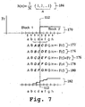
- Figure 7 is a one-dimensional graphical representation providing a generalization of deblocking using frame rate modulation in accordance with one embodiment of the invention.
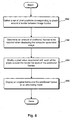
- Figure 8 is a flow chart diagram of the method operations for reducing blocked artifacts between image blocks of a decompressed image in accordance with one embodiment of the invention.
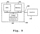
- Figure 9 is a simplified schematic of a device having image deblocking circuitry in accordance with one embodiment of the invention.
- the embodiments of the present invention provide an algorithm for smoothing artificial discontinuities between image blocks (blocking artifacts), without introducing undesired blur.
- the invention can be embodied in an apparatus, methods or programs of instructions.
- the embodiments of the invention are described with respect to low-bit-rate video coding applications, however, it should be appreciated that the embodiments can be applied to any suitable video coding application.
- frame rate modulation is used to smooth blocking artifacts between image blocks.
- a frame rate is the frequency at which the screen, such as a flat panel display, is refreshed.
- the most commonly used flat panel displays for portable devices are Super-twisted Neumatic (STN) Liquid Crystal Display (LCD) panels, whose response time is on the order of hundreds of milliseconds.
- STN Super-twisted Neumatic
- LCD Liquid Crystal Display
- the refresh rate period for these panels is typically around 16 milliseconds (ms).
- frame rate modulation as described herein takes advantage of this difference of the STN LCD panels to increase the number of displayed gray shades in one embodiment of the invention.
- the pixel is energized every other frame, i.e., 2 frames are needed where each pixel is turned on once in an alternating fashion.
- the pixel is shown every other frame to provide the appearance of a gray shade equal to 50% of the pixel brightness when the pixel is in a constant on state.
- FIG. 3 is a simplified schematic diagram representing alternative modes of achieving the smoothing of block discontinuities between adjacent blocks of a video image in accordance with one embodiment of the invention.
- One-dimensional representation 110 represents the results of averaging adjacent pixel values at boundary 112.
- one-dimensional representation 118 is an initial frame f n where block boundary 112 corresponds with a change in pixel values as represented by line 116a.
- additional frame f n 2 is defined, as represented in schematic 120.
- Frame f n 2 120 is similar to initial frame f n 118 with the exception that the pixel values for pixel position B and pixel position C of frame f n 118 have been swapped in frame f n 2 120.
- the visual perception of an observer will be the same perception as frame f n ' in schematic 110. That is, the pixel values at pixel position B and pixel position C will be perceived by a viewer as approximately 50% less than the pixel value for pixel position D as represented in frame f n ' of schematic 110 by line 114.
- the block discontinuity at border 112 is smoothed to minimize the blocky effect when a sharp jump at a block boundary is caused by a transition in pixel values.
- the pixel values at boundary 112 can be smoothed by alternately displaying the frames illustrated in schematics 122 and 124.
- the initial frame has the pixel value for pixel position B substituted at pixel position C.
- an observer will similarly see the frame f n ' illustrated in schematic 110, where the pixel value at boundary 112 of pixel B and pixel C is approximately 50% of the pixel value of pixel D.
- any gray shade can be achieved here by altering the number of frames. In one embodiment, as long as a dither matrix is large enough, the number of gray shades is equal to the rank of the dither matrix.
- Figure 4 is a graphical representation of the smoothing effect on blocking artifacts at a block boundary.
- Schematic 130 illustrates the pixel values for a first block having pixels 134-1 through 134-3 compared to the pixels of a second block having pixels 134-4 to 134-6.
- decoded pixels 134-1 through 134-6 can be averaged, i.e., smoothed so that the blocky artifact is minimized, as will be explained in further detail with reference to Figures 6 and 7.
- the sharp transition at block boundary 112 is changed to a gradual transition to reduce blocking artifacts.
- the decoded pixels are only filtered as described in the embodiments herein, if the difference (D) is less than the quantization parameter (QP).
- the sharp transition at block boundary 112 is regarded as a real edge, thus filtering using frame rate modulation is not performed.
- the quantization parameter is set in the encoding stage.
- Figure 5 is another one-dimensional graphical representation of one of the embodiments of Figure 3.
- the frame rate modulation discussed above is used to smooth the discontinuities i.e., blocking artifacts, occurring between the location of pixels D and E of original frame f n 140.
- the smooth block boundary illustrated in frame f n ' 142 is achieved by alternately displaying frame f n 1 144 and f n 2 146. It should be appreciated that f n 1 has the boundary pixel values for pixels D and E swapped, while f n 2 146 is the original blocky signal f n 140.
- the frame rate modulation described herein eliminates the timely and tedious spatial domain low pass filtering while achieving the same results visually.
- Figure 6 is a one-dimensional graphical representation of a scheme for minimizing blocking artifacts using frame rate modulation having the effect of a five tap low pass filter in accordance with one embodiment in the invention.
- blocky signal f n 150 having a blocking artifact at boundary 112 is smoothed as represented by frame f n ' 152.
- the original frame f n 1 154 is alternately displayed with four additional frames.
- the four additional frames, f n 2 156, f n 3 158, f n 4 160 and f n 5 162 modify the pixel values around block border 112 so as to provide a perceived smoothed boundary by a viewer, when the frames are being displayed in an alternating mode.
- any number of suitable modifications can be made to the frames in order to achieve the desired visual effect of a smoothed block boundary. That is, while Figure 6 illustrates the transition occurring between pixel position B and pixel position G occurring in 20% increments, any suitable percentage increment can be achieved by altering the number and the configuration of additional frames being shown. In addition, while four pixel positions (C-F) were selected to be smoothed in Figure 6, any suitable number of pixel positions can be selected to be smoothed. Of course, real edges are prevented from being smoothed by measuring a difference between pixel values at the block boundary and comparing that difference to the quantization parameter. If the difference is greater than the quantization parameter then the filtering described herein is not performed as discussed with reference to Figure 4.
- Figure 7 is a one-dimensional graphical representation providing a generalization of deblocking using frame rate modulation in accordance with one embodiment of the invention.
- Frame (Fr) 170 illustrates the original blocky signal.
- Block 1 includes pixel positions a, b, c, and d.
- Block 2 includes pixel positions e, f, g, and h.
- the pixel values are represented by the upper case letters of the pixel position. For example, pixel position a has a pixel value of A, pixel position b has a pixel value of B, and so on.
- Equation 184 represents the generalization of a n-tap filter in one embodiment of the invention.
- Parameter N represents the sum of the value in the braces of equation 184.
- the user can choose the pixel positions to be blurred, i.e., smoothed.
- pixel positions c, d, e, and f have been chosen to be smoothed with reference to Figure 7, however, more or less pixel positions may be chosen.
- the generalization of deblocking using frame rate modulation is discussed in terms of a five tap filter.
- the four additional frames are Frame 1 172, Frame 2 174, Frame 4 178 and Frame 5 180.
- the original frame is represented by Frame 3 176.
- each of frames 1-5, 172-180 have pixel values associated with the representative pixel position.
- the pixel values associated with pixel positions that were selected to be smoothed have been modified.
- the pixel values associated with pixel position c are now A, B, C, D and E.
- pixel position c is associated with a value that consists of an average of five different pixel values.
- pixel values associated with pixel position d are B, C, D, E and F.
- pixel positions E and F also have modified pixel values.
- any type of averaging can be used, such as a weighted average placing more weight on a particular pixel value.
- the pixel value associated with each of pixel positions a and b of graph 182 is zero. While the pixel value associated with pixel position c is 1 divided by 5, which is 0.2, i.e., 20% of the pixel value associated with the pixels of block 2, and the pixel value associated with pixel d is two divided by five which is 40%. Similarly, the pixel value associated with pixel position e would be 60% or the pixel value associated with pixel position f is 80%. Therefore, a smoother transition is perceived at block boundary 112 rather than a sharp transition from zero to 100%. In essence, the transition steps in 20% increments from zero to 1.
- FIG 8 is a flow chart diagram of the method operations for reducing blocked artifacts between image blocks of a decompressed image in accordance with one embodiment of the invention.
- the method initiates with operation 190 where a set of pixel positions is selected.
- the pixel positions correspond to pixels proximate to a border between adjacent image blocks.
- the pixel positions could be the two adjacent pixel positions on either side of the block boundary as illustrated with reference to Figure 5.
- the pixel positions could be a plurality of pixels on each side of the block boundary, such as the illustrations discussed with reference to Figures 6 and 7.
- the method then advances to operation 192 where an amount of additional frames to be inserted into a display pattern is determined. In one embodiment, where each of the filter coefficients is equally weighted, the amount of additional frames to be inserted in the display pattern is equal to one less than the number of filter coefficients, i.e., one less than the filter tap.
- a pixel value associated with each of the pixels proximate to the border for each of the additional frames is modified.
- the pixel values are manipulated through frame rate modulation as described above.
- the pixel values can be modified so that a gradual step pattern is provided in the region proximate to a block boundary as described with reference to Figure 6 and 7.
- the pixel value of two pixel positions, where each pixel is on opposed sides of a block boundary can be swapped or flipped as illustrated with reference to Figure 5.
- the pixel values are modified after it has been determined that a difference between the values of the decoded pixels from a first block and the values of decoded pixels from a second block is less than the quantization parameter.
- the method then moves to operation 196 where an original frame and the additional frames are displayed in an alternating mode.
- each frame is shown in an alternating fashion to reduce block artifacts by providing a more gradual transition for differences in pixel values at the block boundary. That is, a boundary pixel is energized every other frame to provide a perception of a 50% pixel value in this embodiment.
- the embodiments described herein may apply to the entire block boundary. For example, where a block is bordered by four other blocks on each side, the pixel averaging or pixel swapping described herein may be applied to selected pixels at each side, i.e. each block boundary.
- FIG 9 is a simplified schematic of a device having image deblocking circuitry in accordance with one embodiment of the invention.
- Device 200 includes CPU 202 which is in communication with memory 204 and image deblocking circuitry 206 through bus 208.
- Device 200 displays an image on monitor 210.
- monitor 210 can either be an integral part of device 200 or a stand alone unit.
- image deblocking circuitry 206 is configured to reduce a blocky effect of an image being presented on monitor 210 while minimizing the power consumed.
- deblocking circuitry 206 smoothes a border between image blocks of a frame of image data as discussed above with reference to Figures 3-8.
- deblocking circuitry 206 may be configured to average pixel values proximate to a border between image blocks by alternately displaying an original frame of image data with additional frames of image data, wherein the additional frames of image data have altered pixel values proximate to the border between image blocks. That is, the frame rate modulation discussed above is executed through deblocking circuitry 206 to minimize blocking artifacts of an image being displayed.
- device 200 may be configured to be attached to a storage device, such as a hard drive, networked attached storage, etc.
- device 200 may be configured to download image data from a distributed network, such as the Internet.
- the image deblocking circuitry is located on a printed circuit board, such as a host bus adapter card.
- the above described invention provides for a method and system for minimizing a blocky effect due to the transition of pixel values across block boundaries.
- the pixel values of pixels positioned at opposite sides of a block boundary are swapped to define an additional frame.
- the additional frame is alternately displayed with an original frame to smooth a blocking artifact.
- the alternate display of the original and the additional frame is also referred to herein as frame rate modulation.
- Frame rate modulation provides a display that has reduced block artifacts.
- a number of pixel positions on each side of a block boundary are swapped to define one or more additional frames.
- the one or more additional frames and the original frame are alternately displayed to minimize any blocky effect.
- the smoothing algorithm is not performed.
- a true edge is determined by a difference between the values of the decoded pixels from a first block and the values of decoded pixels from a second block, where the difference is compared to a quantization parameter set in the encoding stage. More particularly, where the difference in pixel values is greater than the quantization parameter, a true edge occurs at the block boundary, therefore, the smoothing algorithm is not performed in this instance. It should be appreciated that the embodiments described herein reduce blocking artifacts between image blocks without blurring real edges and without tedious low pass filtering in the spatial domain. Thus, for mobile media terminals and devices using embedded systems, where computing power is a higher priority than the quality of the decoded signal, the above described embodiments provide an acceptable picture quality that reduces blocking artifacts while conserving power.
- the invention may employ various computer-implemented operations involving data stored in computer systems. These operations include operations requiring physical manipulation of physical quantities. Usually, though not necessarily, these quantities take the form of electrical or magnetic signals capable of being stored, transferred, combined, compared, and otherwise manipulated. Further, the manipulations performed are often referred to in terms, such as producing, identifying, determining, or comparing.
- the invention can also be embodied as computer readable code on a computer readable medium.
- the computer readable medium is any data storage device that can store data which can be thereafter read by a computer system. Examples of the computer readable medium include hard drives, network attached storage (NAS), read-only memory, random-access memory, CD-ROMs, CD-Rs, CD-RWs, magnetic tapes, and other optical and non-optical data storage devices.
- the computer readable medium can also be distributed over a network coupled computer system so that the computer readable code is stored and executed in a distributed fashion.
Landscapes
- Engineering & Computer Science (AREA)
- Multimedia (AREA)
- Signal Processing (AREA)
- Physics & Mathematics (AREA)
- General Physics & Mathematics (AREA)
- Theoretical Computer Science (AREA)
- Compression Or Coding Systems Of Tv Signals (AREA)
Applications Claiming Priority (2)
| Application Number | Priority Date | Filing Date | Title |
|---|---|---|---|
| US10/247,942 US7031392B2 (en) | 2002-09-20 | 2002-09-20 | Method and apparatus for video deblocking |
| US247942 | 2002-09-20 |
Publications (2)
| Publication Number | Publication Date |
|---|---|
| EP1401212A2 true EP1401212A2 (de) | 2004-03-24 |
| EP1401212A3 EP1401212A3 (de) | 2004-08-18 |
Family
ID=31946450
Family Applications (1)
| Application Number | Title | Priority Date | Filing Date |
|---|---|---|---|
| EP03021223A Withdrawn EP1401212A3 (de) | 2002-09-20 | 2003-09-18 | Verfahren und Vorrichtung zum Entfernen von Blockstrukturen |
Country Status (5)
| Country | Link |
|---|---|
| US (2) | US7031392B2 (de) |
| EP (1) | EP1401212A3 (de) |
| JP (1) | JP2004120748A (de) |
| KR (1) | KR100569162B1 (de) |
| CN (1) | CN100380974C (de) |
Cited By (3)
| Publication number | Priority date | Publication date | Assignee | Title |
|---|---|---|---|---|
| WO2005107265A1 (en) * | 2004-04-30 | 2005-11-10 | Koninklijke Philips Electronics N.V. | Method and device for post-processing image data |
| DE102007037857A1 (de) * | 2007-08-10 | 2009-02-12 | Micronas Gmbh | Verfahren zur Reduktion von Bildartefakten |
| CN102177714A (zh) * | 2008-10-10 | 2011-09-07 | 微软公司 | 重叠变化处理中的减少的dc增益失配和dc泄漏 |
Families Citing this family (29)
| Publication number | Priority date | Publication date | Assignee | Title |
|---|---|---|---|---|
| US7543326B2 (en) * | 2002-06-10 | 2009-06-02 | Microsoft Corporation | Dynamic rate control |
| US20030235250A1 (en) * | 2002-06-24 | 2003-12-25 | Ankur Varma | Video deblocking |
| FR2841423A1 (fr) * | 2002-06-25 | 2003-12-26 | Koninkl Philips Electronics Nv | Procede de detection d'artefacts de bloc |
| US7460596B2 (en) * | 2004-04-29 | 2008-12-02 | Mediatek Incorporation | Adaptive de-blocking filtering apparatus and method for MPEG video decoder |
| US7496141B2 (en) * | 2004-04-29 | 2009-02-24 | Mediatek Incorporation | Adaptive de-blocking filtering apparatus and method for MPEG video decoder |
| US7539248B2 (en) * | 2004-04-29 | 2009-05-26 | Mediatek Incorporation | Adaptive de-blocking filtering apparatus and method for MPEG video decoder |
| US20050243914A1 (en) * | 2004-04-29 | 2005-11-03 | Do-Kyoung Kwon | Adaptive de-blocking filtering apparatus and method for mpeg video decoder |
| US20060013315A1 (en) * | 2004-07-19 | 2006-01-19 | Samsung Electronics Co., Ltd. | Filtering method, apparatus, and medium used in audio-video codec |
| US7961357B2 (en) * | 2004-12-08 | 2011-06-14 | Electronics And Telecommunications Research Institute | Block artifact phenomenon eliminating device and eliminating method thereof |
| US20090016442A1 (en) * | 2005-10-06 | 2009-01-15 | Vvond, Inc. | Deblocking digital images |
| US8023559B2 (en) * | 2005-10-06 | 2011-09-20 | Vudu, Inc. | Minimizing blocking artifacts in videos |
| JP4621574B2 (ja) * | 2005-10-06 | 2011-01-26 | 株式会社東芝 | 画像符号化装置および画像符号化方法 |
| KR100745837B1 (ko) * | 2005-11-30 | 2007-08-02 | 엠텍비젼 주식회사 | 여유 데이터가 부가된 화소 데이터 출력 방법 및 장치 |
| WO2008084996A1 (en) * | 2007-01-11 | 2008-07-17 | Samsung Electronics Co, . Ltd. | Method and apparatus for deblocking-filtering video data |
| GB2451437B (en) * | 2007-07-27 | 2012-11-14 | Hewlett Packard Development Co | Content encoder and decoder and methods of encoding and decoding content |
| US8913670B2 (en) * | 2007-08-21 | 2014-12-16 | Blackberry Limited | System and method for providing dynamic deblocking filtering on a mobile device |
| US8369638B2 (en) | 2008-05-27 | 2013-02-05 | Microsoft Corporation | Reducing DC leakage in HD photo transform |
| US8447591B2 (en) * | 2008-05-30 | 2013-05-21 | Microsoft Corporation | Factorization of overlapping tranforms into two block transforms |
| CA2684678A1 (en) * | 2009-11-03 | 2011-05-03 | Research In Motion Limited | System and method for dynamic post-processing on a mobile device |
| JP6191160B2 (ja) * | 2012-07-12 | 2017-09-06 | ノーリツプレシジョン株式会社 | 画像処理プログラムおよび画像処理装置 |
| US10356410B2 (en) | 2014-10-28 | 2019-07-16 | Sony Corporation | Image processing system with joint encoding and method of operation thereof |
| US10063889B2 (en) | 2014-10-28 | 2018-08-28 | Sony Corporation | Image processing system with conditional coding and method of operation thereof |
| US9294782B1 (en) | 2014-10-28 | 2016-03-22 | Sony Corporation | Image processing system with artifact reduction mechanism and method of operation thereof |
| US9357232B2 (en) | 2014-10-28 | 2016-05-31 | Sony Corporation | Image processing system with binary decomposition and method of operation thereof |
| US9674554B2 (en) | 2014-10-28 | 2017-06-06 | Sony Corporation | Image processing system with coding mode and method of operation thereof |
| US9591330B2 (en) | 2014-10-28 | 2017-03-07 | Sony Corporation | Image processing system with binary adaptive Golomb coding and method of operation thereof |
| US11016212B2 (en) * | 2017-04-11 | 2021-05-25 | Saudi Arabian Oil Company | Compressing seismic wavefields in three-dimensional reverse time migration |
| US11656378B2 (en) | 2020-06-08 | 2023-05-23 | Saudi Arabian Oil Company | Seismic imaging by visco-acoustic reverse time migration |
| WO2022116054A1 (zh) * | 2020-12-02 | 2022-06-09 | Oppo广东移动通信有限公司 | 图像处理方法、系统、视频编码器及视频解码器 |
Family Cites Families (24)
| Publication number | Priority date | Publication date | Assignee | Title |
|---|---|---|---|---|
| US5107348A (en) * | 1990-07-11 | 1992-04-21 | Zenith Electronics Corporation | Temporal decorrelation of block artifacts |
| US5454051A (en) * | 1991-08-05 | 1995-09-26 | Eastman Kodak Company | Method of reducing block artifacts created by block transform compression algorithms |
| KR0166717B1 (ko) | 1992-06-18 | 1999-03-20 | 강진구 | 가변화면분할기법을 이용한 부호화/복호화방법 및 장치 |
| KR0165497B1 (ko) * | 1995-01-20 | 1999-03-20 | 김광호 | 블럭화현상 제거를 위한 후처리장치 및 그 방법 |
| KR0155890B1 (ko) * | 1995-09-28 | 1998-12-15 | 윤종용 | 화상 표시 장치의 다계조 표시 구동 방법 |
| US6151420A (en) * | 1995-12-15 | 2000-11-21 | Polaroid Corporation | Minimizing blocking artifacts in a filtered image |
| KR100242636B1 (ko) * | 1996-03-23 | 2000-02-01 | 윤종용 | 블록화효과 및 링잉노이즈 감소를 위한 신호적응후처리시스템 |
| DE19626985C1 (de) * | 1996-07-04 | 1998-01-02 | Siemens Ag | Verfahren und Anordnung zur Reduktion von Codierungsartefakten von blockbasierten Bildcodierungsverfahren und objektbasierten Bildcodierungsverfahren |
| KR100213089B1 (ko) * | 1997-01-29 | 1999-08-02 | 윤종용 | 루프필터링 방법 및 루프필터 |
| US6188799B1 (en) * | 1997-02-07 | 2001-02-13 | Matsushita Electric Industrial Co., Ltd. | Method and apparatus for removing noise in still and moving pictures |
| US6035060A (en) * | 1997-02-14 | 2000-03-07 | At&T Corp | Method and apparatus for removing color artifacts in region-based coding |
| JP3095140B2 (ja) * | 1997-03-10 | 2000-10-03 | 三星電子株式会社 | ブロック化効果の低減のための一次元信号適応フィルター及びフィルタリング方法 |
| KR100234316B1 (ko) * | 1997-04-04 | 1999-12-15 | 윤종용 | 링잉노이즈 감소를 위한 신호적응 필터링 방법 및 신호적응필터 |
| KR100211123B1 (ko) | 1997-05-23 | 1999-07-15 | 윤종용 | 고속 패킷 스위칭을 위한 다단 상호 연결 망 |
| US6335990B1 (en) * | 1997-07-03 | 2002-01-01 | Cisco Technology, Inc. | System and method for spatial temporal-filtering for improving compressed digital video |
| US6064359A (en) * | 1997-07-09 | 2000-05-16 | Seiko Epson Corporation | Frame rate modulation for liquid crystal display (LCD) |
| KR100281099B1 (ko) * | 1997-07-30 | 2001-04-02 | 구자홍 | 동영상의부호화에따른블록화현상제거방법 |
| KR100244290B1 (ko) * | 1997-09-09 | 2000-02-01 | 구자홍 | 저속 전송에서의 동영상을 위한 디블록킹 필터링 방법 |
| US6229929B1 (en) * | 1998-05-14 | 2001-05-08 | Interval Research Corporation | Border filtering of video signal blocks |
| US6285801B1 (en) * | 1998-05-29 | 2001-09-04 | Stmicroelectronics, Inc. | Non-linear adaptive image filter for filtering noise such as blocking artifacts |
| US6141380A (en) * | 1998-09-18 | 2000-10-31 | Sarnoff Corporation | Frame-level rate control for video compression |
| US6317522B1 (en) | 1998-12-03 | 2001-11-13 | Philips Electronics North America Corp. | Systems and methods for post-processing decompressed images |
| KR100335055B1 (ko) * | 1999-12-08 | 2002-05-02 | 구자홍 | 압축 영상신호의 블럭현상 및 링현상 제거방법 |
| FI117534B (fi) * | 2000-01-21 | 2006-11-15 | Nokia Corp | Menetelmä digitaalisten kuvien suodattamiseksi ja suodatin |
-
2002
- 2002-09-20 US US10/247,942 patent/US7031392B2/en not_active Expired - Fee Related
-
2003
- 2003-07-25 KR KR1020030051398A patent/KR100569162B1/ko not_active Expired - Fee Related
- 2003-09-18 EP EP03021223A patent/EP1401212A3/de not_active Withdrawn
- 2003-09-19 CN CNB031586627A patent/CN100380974C/zh not_active Expired - Fee Related
- 2003-09-19 JP JP2003327974A patent/JP2004120748A/ja not_active Withdrawn
-
2006
- 2006-01-31 US US11/344,252 patent/US7623577B2/en not_active Expired - Fee Related
Cited By (5)
| Publication number | Priority date | Publication date | Assignee | Title |
|---|---|---|---|---|
| WO2005107265A1 (en) * | 2004-04-30 | 2005-11-10 | Koninklijke Philips Electronics N.V. | Method and device for post-processing image data |
| DE102007037857A1 (de) * | 2007-08-10 | 2009-02-12 | Micronas Gmbh | Verfahren zur Reduktion von Bildartefakten |
| CN102177714A (zh) * | 2008-10-10 | 2011-09-07 | 微软公司 | 重叠变化处理中的减少的dc增益失配和dc泄漏 |
| CN102177714B (zh) * | 2008-10-10 | 2014-01-08 | 微软公司 | 重叠变化处理中的减少的dc增益失配和dc泄漏 |
| RU2518932C2 (ru) * | 2008-10-10 | 2014-06-10 | Майкрософт Корпорейшн | Уменьшенное рассогласование коэффициентов усиления постоянной состовляющей (dc) и dc-утечки при обработке преобразования с перекрытием |
Also Published As
| Publication number | Publication date |
|---|---|
| CN1492686A (zh) | 2004-04-28 |
| EP1401212A3 (de) | 2004-08-18 |
| US7623577B2 (en) | 2009-11-24 |
| KR20040025814A (ko) | 2004-03-26 |
| US20060126731A1 (en) | 2006-06-15 |
| US7031392B2 (en) | 2006-04-18 |
| CN100380974C (zh) | 2008-04-09 |
| US20040057631A1 (en) | 2004-03-25 |
| JP2004120748A (ja) | 2004-04-15 |
| KR100569162B1 (ko) | 2006-04-07 |
Similar Documents
| Publication | Publication Date | Title |
|---|---|---|
| US7031392B2 (en) | Method and apparatus for video deblocking | |
| USRE45135E1 (en) | Method of removing blocking artifacts in a coding system of a moving picture | |
| US6983079B2 (en) | Reducing blocking and ringing artifacts in low-bit-rate coding | |
| US6950473B2 (en) | Hybrid technique for reducing blocking and ringing artifacts in low-bit-rate coding | |
| US7437015B2 (en) | Method of reducing a blocking artifact when coding moving picture | |
| US7031552B2 (en) | Adaptive post-filtering for reducing noise in highly compressed image/video coding | |
| Lee et al. | Optimized brightness compensation and contrast enhancement for transmissive liquid crystal displays | |
| US20050157791A1 (en) | System and method for video tone scale reduction | |
| Zhang et al. | Compression artifact reduction with adaptive bilateral filtering | |
| KR101336629B1 (ko) | 다수의 이전 영상 프레임을 사용하는 lcd 오버드라이브 장치 및 방법 | |
| Dar et al. | Optimized pre-compensating compression | |
| Ding et al. | Video pre-processing with JND-based Gaussian filtering of superpixels | |
| US6980599B2 (en) | Video decoding system and method having post-processing to reduce sharpness prediction drift | |
| Gan et al. | Blocking artifact reduction in compressed images based on edge-adaptive quadrangle meshes | |
| WO2006131866A2 (en) | Method and system for image processing | |
| US6526179B2 (en) | Compression sensitive sharpening | |
| KR20060130676A (ko) | 디지털 비디오 처리를 위한 비디오 인코딩 메트릭을사용하는 휘도 트랜지언트 개선 | |
| Har-Noy et al. | Filter banks for improved LCD motion |
Legal Events
| Date | Code | Title | Description |
|---|---|---|---|
| PUAI | Public reference made under article 153(3) epc to a published international application that has entered the european phase |
Free format text: ORIGINAL CODE: 0009012 |
|
| 17P | Request for examination filed |
Effective date: 20030918 |
|
| AK | Designated contracting states |
Kind code of ref document: A2 Designated state(s): AT BE BG CH CY CZ DE DK EE ES FI FR GB GR HU IE IT LI LU MC NL PT RO SE SI SK TR |
|
| AX | Request for extension of the european patent |
Extension state: AL LT LV MK |
|
| PUAL | Search report despatched |
Free format text: ORIGINAL CODE: 0009013 |
|
| AK | Designated contracting states |
Kind code of ref document: A3 Designated state(s): AT BE BG CH CY CZ DE DK EE ES FI FR GB GR HU IE IT LI LU MC NL PT RO SE SI SK TR |
|
| AX | Request for extension of the european patent |
Extension state: AL LT LV MK |
|
| 17Q | First examination report despatched |
Effective date: 20050311 |
|
| AKX | Designation fees paid |
Designated state(s): AT BE GB |
|
| REG | Reference to a national code |
Ref country code: DE Ref legal event code: 8566 |
|
| RBV | Designated contracting states (corrected) |
Designated state(s): AT BE GB |
|
| STAA | Information on the status of an ep patent application or granted ep patent |
Free format text: STATUS: THE APPLICATION IS DEEMED TO BE WITHDRAWN |
|
| 18D | Application deemed to be withdrawn |
Effective date: 20100401 |