EP1401098A1 - Method and system for power control in radio transceivers and transmitters - Google Patents
Method and system for power control in radio transceivers and transmitters Download PDFInfo
- Publication number
- EP1401098A1 EP1401098A1 EP02020648A EP02020648A EP1401098A1 EP 1401098 A1 EP1401098 A1 EP 1401098A1 EP 02020648 A EP02020648 A EP 02020648A EP 02020648 A EP02020648 A EP 02020648A EP 1401098 A1 EP1401098 A1 EP 1401098A1
- Authority
- EP
- European Patent Office
- Prior art keywords
- power level
- new
- correction parameter
- dac
- detected
- Prior art date
- Legal status (The legal status is an assumption and is not a legal conclusion. Google has not performed a legal analysis and makes no representation as to the accuracy of the status listed.)
- Granted
Links
Images




Classifications
-
- H—ELECTRICITY
- H03—ELECTRONIC CIRCUITRY
- H03G—CONTROL OF AMPLIFICATION
- H03G3/00—Gain control in amplifiers or frequency changers
- H03G3/20—Automatic control
- H03G3/30—Automatic control in amplifiers having semiconductor devices
- H03G3/3036—Automatic control in amplifiers having semiconductor devices in high-frequency amplifiers or in frequency-changers
- H03G3/3042—Automatic control in amplifiers having semiconductor devices in high-frequency amplifiers or in frequency-changers in modulators, frequency-changers, transmitters or power amplifiers
- H03G3/3047—Automatic control in amplifiers having semiconductor devices in high-frequency amplifiers or in frequency-changers in modulators, frequency-changers, transmitters or power amplifiers for intermittent signals, e.g. burst signals
Definitions
- the invention relates generally to power control in a radio transceiver or transmitter. More specifically, the invention relates to power control in situations where some environmental conditions influencing the transceiver or some other system characteristics change.
- Mobile terminals used in mobile networks have to comply with the power level instructions received from the network.
- 3GPP TS 45.005 (Third Generation Partnership Project; Technical Specification Group; GSM/EDGE Radio Access Network: Radio Transmission and Reception)
- GSM/EDGE Radio Access Network Radio Transmission and Reception
- some power levels for mobile terminals in different Global System for Mobile Communications GSM and Enhanced Data rates for GSM Evolution EDGE mobile networks are disclosed.
- the mobile network monitors the output power level of a cellular telephone within the network coverage.
- the mobile network transmits power level setting commands to the mobile terminals which need to obey the power level setting commands received. This is important especially for minimising the amount of inter-cell interference so that channel capacity can be maximised.
- the mobile terminals In order for the mobile terminals to effectively control the transmitted power and thus to avoid deteriorating the efficiency of the mobile network, the mobile terminals need to comprise a power control system for their radio transceivers.
- a modern output power control system of a transmitter has been disclosed in the international patent application WO 01/84741 A2.
- the patent publication discloses a software power control system that can take into account fluctuations of the output power level, frequency fluctuations of the transmitter, and fluctuations of the supply voltage.
- the calibration of the power control system can be implemented using software so that data identifying calibration points are stored into memory. This data corresponds to frequency and output power control values, for example. The data identifying the calibration is then used when actually correcting the power control system.
- the problem related with any stored power control calibration is that if some characteristic of a system component changes, this change may induce some additional error not taken into account in the original calibration. For example, if the antenna impedance changes due to changing antenna near-field environments, or if the temperature of the mobile terminal changes, or if the power supply of the mobile terminal is changed, the previously stored calibration may be faulty.
- a similar solution to '741 can be implemented using hardware circuit as presented in UK patent application GB 2292276 A.
- predetermined values are stored and used so that a particular transmission level is output for each time slot.
- a comparator in the system compares the transmission level actually detected by the level detector in each time slot against the corresponding pre-selected value.
- a level adjusting circuit then corrects the pre-selected value on the basis of the output of the comparator, for example by adding a small value to the pre-selected value. This correction is used in the transceiver.
- the correction value may be directly calculated or otherwise produced from the previously stated deviation instead of the small increment or decrement by the predetermined value.
- a power control system to be used for a radio transceiver system includes i) a transmitter for transmitting an input signal using an up- and down-ramp thus producing an output signal having an output power level, and ii) correction means for correcting the operation of the transmitter by correcting the output power of the transmitter with a correction parameter stored in a data storage means, the correction parameter depending at least on one of the following: 1) temperature, 2) channel frequency, and 3) supply voltage, the correction causing a change in the output power level.
- the system includes iii) power level detection means, for detecting a power level representing the output power of the transmitted signal, iv) comparing means adapted to compare said detected power level with a target power level thus producing comparison result, v) estimating means responsive to the comparing means, adapted to estimate a new correction parameter if the comparison result shows that the detected power level measured differs from the target power level more than a predetermined threshold value, and vi) storing means adapted to store the new correction parameter into the data storage.
- a power control method for a radio transceiver includes the steps of i) transmitting an input signal using an up- and down-ramp, the output signal having an output power level, ii) correcting the up- and down-ramp used in the transmitting step by the correction parameter selected. Further, the method contains the steps of iii) detecting power level of the output signal, iv) comparing the detected power with a target power, v) estimating a new correction value if the result of the comparing step shows that the power level detected differs from the target power level more than a predetermined threshold value, and vi) storing said correction value to be used in the selecting step, thus creating a self learning system.
- FIG. 1 illustrates the actual power control system in accordance with an aspect of the present invention.
- the transmitter 102 amplifies an input signal S IN which originally has power PIN to an output signal S OUT having power P OUT .
- Figure 5 is a schematic diagram of two data bursts.
- the up ramp or up-ramping shape corresponds to a leading edge of the data burst at this point in the transmitter 102 the carrier signal is being transmitted.
- the transmission carrier signal of data burst ends as this is called down ramp or down-ramping.
- the maximum value of the up- and down-ramp defined correspond or can be scaled to fit to the maximum output power of the data burst sent by the transmitter 102.
- the maximum estimated power level PA DAC,MAX is obtained from the maximum value of this down ramp stage. Because data may be included in the bursts, therefore having an effect to the detected power level P A , the detected power levels between the two bursts may differ even ⁇ P A still having acceptable values.
- Figure 6 illustrates the imperfections of a normal environmental effect changing system typically used in a transceiver.
- the erroneous corrections can effect the power level P OUT with which an input signal S IN is going to be transmitted, if the imperfections are not corrected.
- Such imperfections may arise from a single component's sensitivity changes in the channel frequency CH, supply voltage VACC, or temperature T.
- the maximum estimated power level PA DAC,MAX corresponds ordinarily to the actual power level i.e. to the output power of the power amplifier or transmitter.
- the up- and down-ramp shape PA DAC has to be corrected by the correction parameter ⁇ PA .
- the target output power level P T corresponding to the up- and down-ramp for PA DAC,MAX + ⁇ PA corresponds to the target power level P T , but only if the correction parameter ⁇ PA is correct. Because the correction parameters ⁇ PA can, according to the invention, change during the lifetime of the device wherein the inventive method and/or system is implemented, the target power level can be reached more accurately and faster, thus enhancing the overall system performance.
- the output power P OUT of the signal S OUT needs to be corrected so that the detected power level P A corresponds to the target power level P T .
- the power control system includes also correction means 160 that select the correction parameter ⁇ PA from data storage 110 with which the operation of the transmitter 102 is modified.
- correction means 160 include selecting means 108, setting means 112 and power level estimating means 180.
- the estimated maximum power level PA DAC,MAX is estimated from the temperature, supply voltage and the frequency and maybe the input signal S IN in the power level estimating means 180.
- the estimated maximum power level PA DAC,MAX is passed to selecting means 108.
- the selecting means 108 obtain also data representing temperature T, supply voltage VACC, and channel frequency CH, for example, from the transmitter 102.
- the selecting means 108 request a correction parameter ⁇ PA from the data storage 110.
- the data storage 110 there are stored values corresponding to correction parameters ⁇ PA in respect with the plurality of combinations of the estimated power level PA DAC,MAX , temperature T, supply voltage VACC and channel CH.
- the data storage 110 returns the correction parameter ⁇ PA corresponding to the combination of parameters included in the request.
- the selecting means 108 pass the obtained correction parameter ⁇ PA together with the maximum estimated power level PA DAC,MAX to the setting means 112.
- the setting means 112 perform the actual power control of the transmitter 102 by first calculating and then setting the up- and down-ramp shape PA DAC to the transmitter 102. In order to minimise switching transients, the shape of the up- and down-ramp should be as close as possible to a raised cosine function.
- Figure 2 illustrates how the power control system in accordance with the present invention includes correction changing means 120 for adjusting the correction parameters ⁇ PA stored into the data storage 110.
- the correction changing means 120 include reading means 225, storing means 230, and estimating means 266. Further, a history data storage 210 for storing old correction values may be interpreted to belong to the correction changing means 120 as well.
- the comparing means 262 receive a target power level P T from the signalling unit if the device is a mobile terminal or base station.
- the target power level P T is often dictated by the network in which the phone operates.
- the target power level P T is compared in the comparing means 262 with a detected power level P A obtained from the power level detection means 104 which, for example, produces a voltage in proportion to the output power P OUT of the output signal S OUT .
- the reference value can be obtained using a coupler, for example.
- the comparing means 262 calculate a comparison result ⁇ PL , for example, by subtracting target power level P T from the detected power level P A .
- the comparison result ⁇ PL is sent to the estimating means 266.
- the estimating means 266 obtain also the maximum estimated power level PA DAC,MAX from the power level estimating means 180. Further, the estimating means 266 obtain values of at least one of the following parameters from the transmitter 102: temperature T, supply voltage VACC, channel frequency CH.
- the estimating means 266 are responsive to the comparing means 262 in the sense that they are adapted to estimate a new correction parameter NEW ⁇ PA if the result of the comparison shows that the detected power level P A differs from the target power level P T more than a predetermined threshold value, that is, if the absolute value of ⁇ PL is smaller or larger than the predetermined threshold value. This kind of situation means that the old correction parameters are faulty, and using such parameters leads to an erroneous power control of the transmitter.
- the new correction parameter NEW ⁇ PA is stored into the data storage 110 by the storing means 130 which obtain the new correction parameter NEW ⁇ PA from the estimating means 266.
- the system of Figure 2 includes reading means 125 for reading a stored correction parameter OLD ⁇ PA from the data storage 110 and then passing it to the estimating means 266.
- the estimating means may be adapted to calculate the new correction parameter NEW ⁇ PA based on the value of the old correction parameter OLD ⁇ PA and the comparison result ⁇ PL between the target power level P T and the detected power level P L .
- the purpose of this procedure is to make the system a self-learning; i.e. when the old values are used as a basis for the estimation, the probability that the new the correction parameter NEW ⁇ PA is not too far from the right value already for the first iteration and that statistical variations of the observations are not interpreted in a misleadingly way.
- the system further includes reading means 225 for reading values describing the relationship between the power level PL and the up- and down-ramp PA DAC from a history data storage 210.
- the estimating means 266 are adapted to use also the values read for calculating the new correction parameter NEW ⁇ PA .
- the system may also have storing means 230 that are adapted to store values describing such relationship between the correction parameter ⁇ PL , and the target power level PT and the up- and down-ramp shape PA DAC into the history data storage 210. It is also possible only to store a few ramps and then scale them to fit the corrected output power.
- the history data storage 210 sends the old values describing the relationship between the output power level and the up-and down-ramp PA DAC for a specific parameter or parameters such as temperature T, supply voltage VACC, or channel frequency CH. These parameters are read from the history data storage 210 by the reading means 225 which further pass them to the estimating means 266.
- the estimating means 266 further pass similar relationship data (see the curve of Figure 6) describing the detected power level P A and the up- and down-ramp PA DAC to the storing means 230 which store the data into the history data storage 210.
- the parameters may as well be generated with an arbitrary combination of parameters T, VACC, CH. Thus a curve family is formed.
- the estimating means 266 use the old correction parameters OLD ⁇ PA read from data storage 110 by the reading means 125 for computing a new correction parameter NEW ⁇ PA .
- the estimating means 266 may save new correction parameters NEW ⁇ PA with the help of storing means 130 to the data storage 110.
- FIG 3 is a flow diagram showing some steps used in the power control system and method presented in Figure 1.
- step L1 predefined registers containing data about the system information, such as the contents of the data storage 110, are read.
- the reading step L1 may be performed by the selecting means 108, setting means 112, or there may be a separate software block wherein the registers are read.
- step L3 the power level detection means 104 could measure the highest value of the input signal S IN at the up- and down-ramp position thus obtaining a value corresponding to the maximum estimated power level PA DAC,MAX .
- the power can as well be measured in average over a short time in the data burst, depending on the modulation used in the system.
- step L5 the values of temperature T, supply voltage VACC, and channel frequency CH are received by the selecting means 108 from the transmitter 102 or from the signalling unit.
- step L11 the correction parameter ⁇ PA corresponding to the channel frequency CH, temperature T, supply voltage VACC, and the highest value in the up- and down-ramp, i.e. maximum estimated power level PA DAC,MAX is selected in the selecting means 108.
- the selecting means 108 requests the detected power level value P A from the data storage 110 by sending a request for the highest value in the up- and down-ramp PA DAC,MAX , temperature T, supply voltage VACC, and channel frequency CH.
- the data storage 110 responds by returning the correction parameter ⁇ PA to the selecting means 108.
- the selecting means 108 then send the value of ⁇ PA to the setting means 112 which in the step L13 correct the highest value of the up- and down-ramp PA DAC,MAX with the correction parameter ⁇ PA and then calculate in step L15 the up- and down-ramp shape PA DAC using the corrected highest value of the up- and down-ramp PA DAC,MAX .
- the setting means 112 pass this the up-and down-ramp shape PA DAC to the transmitter 102 which then in step L17 transmits the signal S IN using the up- and down-ramp shape PA DAC .
- the output power P OUT is dependent on various parameters.
- the loop described with reference to Figure 3 selects a correct correction parameter.
- FIG. 4 illustrates a flow diagram describing how the power control can be made adjustable in accordance with the present invention.
- the detected power level P A is measured by the power level detection means 104.
- the detected power level P A represents that the signal S OUT is being transmitted with a power P OUT .
- step L23 the comparing means 262 compare the detected power level P A with the target power level P T which has been obtained from the signalling unit.
- step L25 it is checked whether the detected power level P A is acceptable: the comparison result ⁇ PL obtained from the comparing means 262 is compared in the estimating means 266 against a predefined threshold value.
- the correction loop returns to the beginning i.e. to step L21 and continues with obtaining a new detected power level P A for a subsequent part of some other coming data burst.
- step L25 the estimating means 266 estimates in step L27 a new correction parameter NEW ⁇ PA .
- this new correction parameter NEW ⁇ PA may also be a function of channel frequency CH, temperature T, and supply voltage VACC.
- the new correction parameter NEW ⁇ PA is stored by the storing means 130 to the data storage 110.
- the adjusting loop begins again at step L 21.
- the difference between the corrected output power and the ramp height is non-existent when the ramp has been scaled to fit.
- a raised cosine wave form can easily be scaled.
- the history data storage 210 may be used for storing a history showing the evolution of this relationship spanned over discrete set of changes in the parameter ⁇ T, VACC, CH ⁇ space.
- the power level correction system itself is a self-learning system instead of the prior art solutions using fixed correction values.
- Figure 7 shows how up- and down-ramp shapes change by different modulations.
- Figure 7 are both GMSK and 8-PSK modulations illustrated.
- the output power decreases at the down ramp phase.
- an input signal is transmitted using an up- and down-ramp, wherein the output signal should have a predetermined output power level.
- the power level for the output signal is estimated from a table look-up fixed by frequency, temperature and supply voltage, for example.
- a correction value is selected from data storage means wherein correction values for the up-and down-ramp of the transmitting means are stored. There may be different up- and down-ramps for different output powers that are scaled to fit the corrected output power.
- the selecting means are adapted to use in the selection the value describing the combination with at least one of the following i) temperature, ii) supply voltage, or iii) channel frequency.
- the up- and down-ramp used in the transmitting means is corrected with the correction parameter selected. Further, the output power level is detected and a detected power level is compared with a target power level. If the result of the comparison shows that the power level detected differs from the target power level more than a predetermined threshold value, a new correction parameter is estimated and then stored into the data storage means.
- an old correction parameter is read from the data storage means and then used in calculating the new correction parameter. Also the difference between the target power level and the detected power level may be used in the calculation.
- a value describing the relationship between a power level and an up-and down-ramp is read from a history data storage. This value is then used for estimating the new correction value.
- the system may include a history data storage into which values describing the relationship between the power level measured and the up- and down-ramp are stored.
- the invention suits especially well for both constant envelope and non-constant envelope modulation schemes, for example those used in the mobile networks, such as in the Universal Mobile Telecommunication System UMTS, or the Enhanced Data rates for GSM Evolution EDGE networks. Similarly, it may be used in both mobile terminals and base stations.
Landscapes
- Transmitters (AREA)
Abstract
Description
- The invention relates generally to power control in a radio transceiver or transmitter. More specifically, the invention relates to power control in situations where some environmental conditions influencing the transceiver or some other system characteristics change.
- Mobile terminals used in mobile networks have to comply with the power level instructions received from the network. For example, in the specification 3GPP TS 45.005 (Third Generation Partnership Project; Technical Specification Group; GSM/EDGE Radio Access Network: Radio Transmission and Reception), some power levels for mobile terminals in different Global System for Mobile Communications GSM and Enhanced Data rates for GSM Evolution EDGE mobile networks are disclosed.
- The mobile network monitors the output power level of a cellular telephone within the network coverage. The mobile network transmits power level setting commands to the mobile terminals which need to obey the power level setting commands received. This is important especially for minimising the amount of inter-cell interference so that channel capacity can be maximised.
- In order for the mobile terminals to effectively control the transmitted power and thus to avoid deteriorating the efficiency of the mobile network, the mobile terminals need to comprise a power control system for their radio transceivers.
- Software power control is favourable to a power control system realised with circuit board electronics, because a power loop system easily consumes lots of space on the circuit board.
- A modern output power control system of a transmitter has been disclosed in the international patent application WO 01/84741 A2. The patent publication discloses a software power control system that can take into account fluctuations of the output power level, frequency fluctuations of the transmitter, and fluctuations of the supply voltage.
- As disclosed in the '741, the calibration of the power control system can be implemented using software so that data identifying calibration points are stored into memory. This data corresponds to frequency and output power control values, for example. The data identifying the calibration is then used when actually correcting the power control system.
- The problem related with any stored power control calibration is that if some characteristic of a system component changes, this change may induce some additional error not taken into account in the original calibration. For example, if the antenna impedance changes due to changing antenna near-field environments, or if the temperature of the mobile terminal changes, or if the power supply of the mobile terminal is changed, the previously stored calibration may be faulty.
- Using such a calibration leads to errors in the power control procedure.
- A similar solution to '741 can be implemented using hardware circuit as presented in UK patent application GB 2292276 A. In the '276 application, predetermined values are stored and used so that a particular transmission level is output for each time slot. A comparator in the system compares the transmission level actually detected by the level detector in each time slot against the corresponding pre-selected value. A level adjusting circuit then corrects the pre-selected value on the basis of the output of the comparator, for example by adding a small value to the pre-selected value. This correction is used in the transceiver. Alternatively, to correct the control data the correction value may be directly calculated or otherwise produced from the previously stated deviation instead of the small increment or decrement by the predetermined value.
- Obviously, the solution presented in '276 does not help either in constructing such a system that is not only cheap to produce but also provides the mobile terminal and especially its transceiver with a power control system that is invariant to changes in the terminal characteristics that occur after the manufacturing step.
- It is an object of the invention to obtain a solution by means of which it is possible to alleviate or eliminate at least some of the drawbacks in the radio transceiver power control system especially used in a mobile terminal, what regards to the life cycle changes in the different system components. Another object of the invention is to bring about a system that provides the device with the fast and reliable power control system.
- This and other objectives of the invention are accomplished in accordance with the principles of the present invention as described in any one of the independent patent claims.
- A power control system to be used for a radio transceiver system includes i) a transmitter for transmitting an input signal using an up- and down-ramp thus producing an output signal having an output power level, and ii) correction means for correcting the operation of the transmitter by correcting the output power of the transmitter with a correction parameter stored in a data storage means, the correction parameter depending at least on one of the following: 1) temperature, 2) channel frequency, and 3) supply voltage, the correction causing a change in the output power level. Further, the system includes iii) power level detection means, for detecting a power level representing the output power of the transmitted signal, iv) comparing means adapted to compare said detected power level with a target power level thus producing comparison result, v) estimating means responsive to the comparing means, adapted to estimate a new correction parameter if the comparison result shows that the detected power level measured differs from the target power level more than a predetermined threshold value, and vi) storing means adapted to store the new correction parameter into the data storage.
- A power control method for a radio transceiver includes the steps of i) transmitting an input signal using an up- and down-ramp, the output signal having an output power level, ii) correcting the up- and down-ramp used in the transmitting step by the correction parameter selected. Further, the method contains the steps of iii) detecting power level of the output signal, iv) comparing the detected power with a target power, v) estimating a new correction value if the result of the comparing step shows that the power level detected differs from the target power level more than a predetermined threshold value, and vi) storing said correction value to be used in the selecting step, thus creating a self learning system.
- In the following, the invention and its preferred embodiments are described more closely referring to the examples shown in Figures 1 to 7 in the appended drawings, wherein
- Figure 1
- illustrates the controlling system of the up- and down-ramp of the radio transceiver,
- Figure 2
- illustrates the adaptive power control system, which adjusts the power control performed in the system of Figure 1,
- Figure 3
- is a flow diagram illustrating the main part in which the power control of the system shown in Figure 1 is performed,
- Figure 4
- illustrates the principle with which the adaptive power control system of Figure 2 works,
- Figure 5
- illustrates a data burst showing how the reference value PADAC,MAX can be obtained,
- Figure 6
- illustrates how a power correction value can be obtained, and
- Figure 7
- shows the detected power level PA changes at down-or up-ramp positions for GMSK and 8-PSK modulations.
- Like reference numbers denote similar items throughout the figures.
- Figure 1 illustrates the actual power control system in accordance with an aspect of the present invention. The
transmitter 102 amplifies an input signal SIN which originally has power PIN to an output signal SOUT having power POUT. - The nature of the input signal SIN to be transmitted, as well as conceptualisation of the different power levels extensively used in the description of the invention are shortly characterised with reference to Figures 5 and 6.
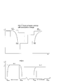
- Figure 5 is a schematic diagram of two data bursts. The up ramp or up-ramping shape corresponds to a leading edge of the data burst at this point in the
transmitter 102 the carrier signal is being transmitted. Correspondingly, when the transmission carrier signal of data burst ends as this is called down ramp or down-ramping. The maximum value of the up- and down-ramp defined correspond or can be scaled to fit to the maximum output power of the data burst sent by thetransmitter 102. In the example of Figure 5 the maximum estimated power level PADAC,MAX is obtained from the maximum value of this down ramp stage. Because data may be included in the bursts, therefore having an effect to the detected power level PA, the detected power levels between the two bursts may differ even ΔPA still having acceptable values. - Figure 6 illustrates the imperfections of a normal environmental effect changing system typically used in a transceiver. The erroneous corrections can effect the power level POUT with which an input signal SIN is going to be transmitted, if the imperfections are not corrected. Such imperfections may arise from a single component's sensitivity changes in the channel frequency CH, supply voltage VACC, or temperature T. The maximum estimated power level PADAC,MAX corresponds ordinarily to the actual power level i.e. to the output power of the power amplifier or transmitter.
- If the detected power level PA is smaller than the target power level PT by the amount of the comparison result ΔPL, the up- and down-ramp shape PADAC has to be corrected by the correction parameter ΔPA. As seen in the Figure 6, the target output power level PT corresponding to the up- and down-ramp for PADAC,MAX + ΔPA corresponds to the target power level PT, but only if the correction parameter ΔPA is correct. Because the correction parameters ΔPA can, according to the invention, change during the lifetime of the device wherein the inventive method and/or system is implemented, the target power level can be reached more accurately and faster, thus enhancing the overall system performance.
- Now referring back to Figure 1; the output power POUT of the signal SOUT needs to be corrected so that the detected power level PA corresponds to the target power level PT. For this purpose the power control system includes also correction means 160 that select the correction parameter ΔPA from
data storage 110 with which the operation of thetransmitter 102 is modified. - In the following the functionality of an example configuration of the correction means 160 is closer illustrated, wherein the correction means 160 include selecting
means 108, setting means 112 and power level estimating means 180. - The estimated maximum power level PADAC,MAX is estimated from the temperature, supply voltage and the frequency and maybe the input signal SIN in the power level estimating means 180. The estimated maximum power level PADAC,MAX is passed to selecting
means 108. The selecting means 108 obtain also data representing temperature T, supply voltage VACC, and channel frequency CH, for example, from thetransmitter 102. - On the basis of the estimated maximum power level PADAC,MAX, temperature T, supply voltage VACC, and channel frequency CH, the selecting means 108 request a correction parameter ΔPA from the
data storage 110. In thedata storage 110 there are stored values corresponding to correction parameters ΔPA in respect with the plurality of combinations of the estimated power level PADAC,MAX, temperature T, supply voltage VACC and channel CH. - The
data storage 110 returns the correction parameter ΔPA corresponding to the combination of parameters included in the request. The selecting means 108 pass the obtained correction parameter ΔPA together with the maximum estimated power level PADAC,MAX to the setting means 112. The setting means 112 perform the actual power control of thetransmitter 102 by first calculating and then setting the up- and down-ramp shape PADAC to thetransmitter 102. In order to minimise switching transients, the shape of the up- and down-ramp should be as close as possible to a raised cosine function. - Figure 2 illustrates how the power control system in accordance with the present invention includes correction changing means 120 for adjusting the correction parameters ΔPA stored into the
data storage 110. The correction changing means 120 include reading means 225, storing means 230, and estimating means 266. Further, ahistory data storage 210 for storing old correction values may be interpreted to belong to the correction changing means 120 as well. The comparing means 262 receive a target power level PT from the signalling unit if the device is a mobile terminal or base station. - The target power level PT is often dictated by the network in which the phone operates. The target power level PT is compared in the comparing means 262 with a detected power level PA obtained from the power level detection means 104 which, for example, produces a voltage in proportion to the output power POUT of the output signal SOUT. The reference value can be obtained using a coupler, for example. The comparing means 262 calculate a comparison result ΔPL, for example, by subtracting target power level PT from the detected power level PA. The comparison result ΔPL is sent to the estimating means 266.
- The estimating means 266 obtain also the maximum estimated power level PADAC,MAX from the power level estimating means 180. Further, the estimating means 266 obtain values of at least one of the following parameters from the transmitter 102: temperature T, supply voltage VACC, channel frequency CH.
- The estimating means 266 are responsive to the comparing means 262 in the sense that they are adapted to estimate a new correction parameter NEW ΔPA if the result of the comparison shows that the detected power level PA differs from the target power level PT more than a predetermined threshold value, that is, if the absolute value of ΔPL is smaller or larger than the predetermined threshold value. This kind of situation means that the old correction parameters are faulty, and using such parameters leads to an erroneous power control of the transmitter.
- The new correction parameter NEW ΔPA is stored into the
data storage 110 by the storing means 130 which obtain the new correction parameter NEW ΔPA from the estimating means 266. - Further, the system of Figure 2 includes reading means 125 for reading a stored correction parameter OLD ΔPA from the
data storage 110 and then passing it to the estimating means 266. The estimating means may be adapted to calculate the new correction parameter NEW ΔPA based on the value of the old correction parameter OLD ΔPA and the comparison result ΔPL between the target power level PT and the detected power level PL. The purpose of this procedure is to make the system a self-learning; i.e. when the old values are used as a basis for the estimation, the probability that the new the correction parameter NEW ΔPA is not too far from the right value already for the first iteration and that statistical variations of the observations are not interpreted in a misleadingly way. This enhances the system performance, especially when the effect of the characteristic changes in the component characteristics, are minor. All the default values for power control can be downloaded intodata storage 110 in the production. No power adjustments are really needed as long as the characteristics of the power detector are known. This makes the power control self-learning. - In accordance with one aspect of the present invention, the system further includes reading means 225 for reading values describing the relationship between the power level PL and the up- and down-ramp PADAC from a
history data storage 210. The estimating means 266 are adapted to use also the values read for calculating the new correction parameter NEW ΔPA. - Respectively, the system may also have storing means 230 that are adapted to store values describing such relationship between the correction parameter ΔPL, and the target power level PT and the up- and down-ramp shape PADAC into the
history data storage 210. It is also possible only to store a few ramps and then scale them to fit the corrected output power. - The
history data storage 210 sends the old values describing the relationship between the output power level and the up-and down-ramp PADAC for a specific parameter or parameters such as temperature T, supply voltage VACC, or channel frequency CH. These parameters are read from thehistory data storage 210 by the reading means 225 which further pass them to the estimating means 266. The estimating means 266 further pass similar relationship data (see the curve of Figure 6) describing the detected power level PA and the up- and down-ramp PADAC to the storing means 230 which store the data into thehistory data storage 210. The parameters may as well be generated with an arbitrary combination of parameters T, VACC, CH. Thus a curve family is formed. - The estimating means 266 use the old correction parameters OLD ΔPA read from
data storage 110 by the reading means 125 for computing a new correction parameter NEW ΔPA. Correspondingly, the estimating means 266 may save new correction parameters NEW ΔPA with the help of storing means 130 to thedata storage 110. - Figure 3 is a flow diagram showing some steps used in the power control system and method presented in Figure 1. In step L1 predefined registers containing data about the system information, such as the contents of the
data storage 110, are read. The reading step L1 may be performed by the selecting means 108, setting means 112, or there may be a separate software block wherein the registers are read. - In step L3 the power level detection means 104 could measure the highest value of the input signal SIN at the up- and down-ramp position thus obtaining a value corresponding to the maximum estimated power level PADAC,MAX. The power can as well be measured in average over a short time in the data burst, depending on the modulation used in the system.
- In step L5 the values of temperature T, supply voltage VACC, and channel frequency CH are received by the selecting means 108 from the
transmitter 102 or from the signalling unit. - The correction parameter ΔPA is a function of the channel frequency CH, temperature T, supply voltage VACC, and the highest value in the up- and down-ramp shape PADAC,MAX and the target power level PT such as the ΔPA = ΔPA(PT, PADAC, T, VACC, CH), defined for the range of parameters.
- In step L11 the correction parameter ΔPA corresponding to the channel frequency CH, temperature T, supply voltage VACC, and the highest value in the up- and down-ramp, i.e. maximum estimated power level PADAC,MAX is selected in the selecting
means 108. The selecting means 108 requests the detected power level value PA from thedata storage 110 by sending a request for the highest value in the up- and down-ramp PADAC,MAX, temperature T, supply voltage VACC, and channel frequency CH. Thedata storage 110 responds by returning the correction parameter ΔPA to the selectingmeans 108. The selecting means 108 then send the value of ΔPA to the setting means 112 which in the step L13 correct the highest value of the up- and down-ramp PADAC,MAX with the correction parameter ΔPA and then calculate in step L15 the up- and down-ramp shape PADAC using the corrected highest value of the up- and down-ramp PADAC,MAX. The setting means 112 pass this the up-and down-ramp shape PADAC to thetransmitter 102 which then in step L17 transmits the signal SIN using the up- and down-ramp shape PADAC. - As already discussed, the output power POUT is dependent on various parameters. The loop described with reference to Figure 3 selects a correct correction parameter.
- When a non-constant envelope modulation scheme, such as 8PSK, is used, information is carried in both the phase and the amplitude of the signal. Therefore the signal will be distorted if the amplitude in any way is changed while transmitting a burst. The ramping changes the amplitude outside the data information in the burst. This means that the ramping procedure/correction is the same; the ramp is scaled to fit to the corrected output power, which is demanded by the network.
- Figure 4 illustrates a flow diagram describing how the power control can be made adjustable in accordance with the present invention. In step L21, the detected power level PA is measured by the power level detection means 104. The detected power level PA represents that the signal SOUT is being transmitted with a power POUT.
- In step L23 the comparing means 262 compare the detected power level PA with the target power level PT which has been obtained from the signalling unit.
- In step L25 it is checked whether the detected power level PA is acceptable: the comparison result ΔPL obtained from the comparing means 262 is compared in the estimating means 266 against a predefined threshold value.
- If the predetermined threshold value is not exceeded, that is, if the detected power level PA is acceptable the correction loop returns to the beginning i.e. to step L21 and continues with obtaining a new detected power level PA for a subsequent part of some other coming data burst.
- In the opposite case, that is, if in step L25 it is detected that the detected power level PA is not acceptable, the estimating means 266 estimates in step L27 a new correction parameter NEW ΔPA. As discussed above, this new correction parameter NEW ΔPA may also be a function of channel frequency CH, temperature T, and supply voltage VACC. In the step L28 the new correction parameter NEW ΔPA is stored by the storing means 130 to the
data storage 110. When the new correction parameter NEW ΔPA has been stored in step L28, the adjusting loop begins again at step L 21. - The difference between the corrected output power and the ramp height is non-existent when the ramp has been scaled to fit. For example, a raised cosine wave form can easily be scaled.
- Correspondingly, the
history data storage 210 may be used for storing a history showing the evolution of this relationship spanned over discrete set of changes in the parameter {T, VACC, CH} space. - As can be noted from the description above, the power level correction system itself is a self-learning system instead of the prior art solutions using fixed correction values.
- Figure 7 shows how up- and down-ramp shapes change by different modulations. In Figure 7 are both GMSK and 8-PSK modulations illustrated. The output power decreases at the down ramp phase.
- To summarise, according to one embodiment of a system according to the present invention, an input signal is transmitted using an up- and down-ramp, wherein the output signal should have a predetermined output power level.
- The power level for the output signal is estimated from a table look-up fixed by frequency, temperature and supply voltage, for example. Further, a correction value is selected from data storage means wherein correction values for the up-and down-ramp of the transmitting means are stored. There may be different up- and down-ramps for different output powers that are scaled to fit the corrected output power. Preferably, the selecting means are adapted to use in the selection the value describing the combination with at least one of the following i) temperature, ii) supply voltage, or iii) channel frequency.
- The up- and down-ramp used in the transmitting means is corrected with the correction parameter selected. Further, the output power level is detected and a detected power level is compared with a target power level. If the result of the comparison shows that the power level detected differs from the target power level more than a predetermined threshold value, a new correction parameter is estimated and then stored into the data storage means.
- According to one aspect of the present invention an old correction parameter is read from the data storage means and then used in calculating the new correction parameter. Also the difference between the target power level and the detected power level may be used in the calculation.
- According to another aspect of the present invention, a value describing the relationship between a power level and an up-and down-ramp is read from a history data storage. This value is then used for estimating the new correction value. Correspondingly, the system may include a history data storage into which values describing the relationship between the power level measured and the up- and down-ramp are stored.
- The transmitter may employ one or more of the variety of transmission techniques for the radio frequency interface such as AMFM, PSK, QPSK, 8-PSK, X-PSK, X-QAM (X=1,2,3,4,5....), TDMA, CDMA, or other techniques, such as constituted by an optical interface like infrared or low-power infrared.
- It is to be noted that the invention suits especially well for both constant envelope and non-constant envelope modulation schemes, for example those used in the mobile networks, such as in the Universal Mobile Telecommunication System UMTS, or the Enhanced Data rates for GSM Evolution EDGE networks. Similarly, it may be used in both mobile terminals and base stations.
- Although the invention above was described with references to the examples shown in the appended drawings, it is obvious that the invention is not limited to these but it may be modified by those skilled in the art without differing from the scope and the spirit of the invention.
-
- 102
- transmitter
- 104
- power level detection means
- 108
- selecting means
- 110
- data storage
- 112
- setting means
- 120
- correction changing means
- 125
- reading means
- 130
- storing means
- 160
- correction means
- 180
- power level estimating means
- 210
- history data storage
- 225
- reading means
- 230
- storing means
- 262
- comparing means
- 266
- estimating means
- CH
- channel frequency
- Pin
- input power
- Pout
- output power
- PA
- detected power level
- ΔPA
- correction parameter
- PT
- target power level
- ΔPL
- comparison result
- PADAC
- up- and down-ramp shape
- PADAC, MAX
- maximum estimated power level
- NEW ΔPA
- new correction parameter
- OLD ΔPA
- old correction parameter
- SIN
- input signal
- Sout
- output signal
- T
- temperature
- VACC
- supply voltage
Claims (13)
- A power control system for a radio transceiver, including:characterised in thata transmitter (102) for transmitting an input signal (SIN) using an up- and down-ramp shape (PADAC) thus producing an output signal (SOUT) having an output power level (POUT);correction means (160) for correcting the operation of the transmitter (102) by correcting the output power of the transmitter (102), with a correction parameter (ΔPA) stored in a data storage (110), the correction parameter depending at least on one of the following: i) temperature (T), ii) channel frequency (CH), and iii) supply voltage (VACC), the correction causing a change in the output power level (POUT); the system
it further includes:power level detection means (104), for detecting a power level (PA) representing the output power (POUT) of the transmitted signal (SOUT);comparing means (262) adapted to compare said detected power level (PA) with a target power level (PT) thus producing comparison result (ΔPL);estimating means (266) responsive to the comparing means, (262), adapted to estimate a new correction parameter (NEW ΔPA) if the comparison result (ΔPL) shows that the detected power level (PA) measured differs from the target power level (PT) more than a predetermined threshold value; andstoring means (130) adapted to store the new correction parameter (NEW ΔPA) into the data storage (110). - A system according to claim 1,
wherein the system further includes:wherein:reading means (125) for reading a stored correction parameter (OLD ΔPA) from the data storage (110); andthe estimating means (266) are adapted to calculate the new correction parameter (NEW ΔPA) based on the parameter (OLD ΔPA) read from the data storage (110), and the difference (ΔPL) between predefined power level (PT) and detected power level (PA). - A system according to claim 2,
wherein the system further includes:reading means (225) for reading a value describing relationship between a power level (PL) and an up- and down-ramp shape (PADAC) from a history data storage (210); and wherein:the estimating means (266) are adapted to use also the value read in calculating the new correction parameter (NEW ΔPA). - A system according to claim 1,
wherein the system further includes: storing means (230) for storing a value describing relationship between the power level detected (PA), and the up- and down-ramp shape (PADAC) into a history data storage (210) . - A system according to any one of the preceding claims,
wherein the correction means (160) are further adapted to fit ramping of the transceiver (102) to the corrected output power, thus making burst to burst output power and ramping correction. - A system according to any one of the preceding claims, wherein the system further includes: storing means (230) for storing a value or scaled according to the corrected output power.
- A mobile terminal or a base station,
wherein a power control system according to any one of the preceding claims is used. - A power control method for a radio transceiver, the method including the steps of:characterised in thattransmitting (L17) an input signal (SIN) using an the up- and down-ramp shape (PADAC) , the output signal (SOUT) having an output power level (POUT); andcorrecting (L13) the up- and down-ramp shape (PADAC) used in the transmitting step (L17) by the correction parameter (ΔPA) selected; the method
it further contains the steps of:detecting (L21) power level (PA) of the output signal;comparing (L23) the detected power (PA) with a target power level (PT);estimating (L27) a new correction parameter (NEW ΔPA) if the result of the comparing step shows that the power level (PA) detected differs from the target power level (PT) more than a predetermined threshold value; andstoring (L28) said correction parameter (NEW ΔPA) to be used in the selecting step (L11), thus creating a self learning system. - A method according to claim 8,
characterised in that
the method further includes the step of:wherein:reading a stored correction parameter (OLD ΔPA); andin the estimating step (L27) a new correction parameter (NEW ΔPA) is calculated based on the parameter (OLD ΔPA) read, and the difference (ΔPL) between the predefined power level (PT) and the detected power level (PA). - A method according to claim 9,
characterised in that
the method further includes the step of:wherein:reading a value describing relationship between a power level (PL) and an up- and down-ramp shape (PADAC); andin the estimating step (L27) also the value read is used in calculating the new correction value (NEW ΔPA). - A method according to claim 10,
characterised in that
the method further includes the step of: storing a value describing relationship between the power level detected (PA) , and the up- and down-ramp shape (PADAC) . - A method according to any one of the preceding claims 8-11,
wherein the ramping is scaled to fit the corrected output power. - A method according to any one of the claims 8-12,
characterised in that
the method is used in a mobile terminal or in a base station.
Priority Applications (1)
| Application Number | Priority Date | Filing Date | Title |
|---|---|---|---|
| EP20020020648 EP1401098B1 (en) | 2002-09-11 | 2002-09-13 | Method and system for power control in radio transceivers and transmitters |
Applications Claiming Priority (3)
| Application Number | Priority Date | Filing Date | Title |
|---|---|---|---|
| EP02020320A EP1398874B1 (en) | 2002-09-11 | 2002-09-11 | Method and system for power control in radio transmitters |
| EP02020320 | 2002-09-11 | ||
| EP20020020648 EP1401098B1 (en) | 2002-09-11 | 2002-09-13 | Method and system for power control in radio transceivers and transmitters |
Publications (2)
| Publication Number | Publication Date |
|---|---|
| EP1401098A1 true EP1401098A1 (en) | 2004-03-24 |
| EP1401098B1 EP1401098B1 (en) | 2008-10-15 |
Family
ID=31947892
Family Applications (1)
| Application Number | Title | Priority Date | Filing Date |
|---|---|---|---|
| EP20020020648 Expired - Lifetime EP1401098B1 (en) | 2002-09-11 | 2002-09-13 | Method and system for power control in radio transceivers and transmitters |
Country Status (1)
| Country | Link |
|---|---|
| EP (1) | EP1401098B1 (en) |
Cited By (1)
| Publication number | Priority date | Publication date | Assignee | Title |
|---|---|---|---|---|
| EP2254237A3 (en) * | 2009-05-21 | 2011-03-30 | Huawei Technologies Co., Ltd. | Method and device for adjusting power amplifier voltage and controlling time slots |
Citations (2)
| Publication number | Priority date | Publication date | Assignee | Title |
|---|---|---|---|---|
| WO2001050632A1 (en) * | 1999-12-30 | 2001-07-12 | Telefonaktiebolaget Lm Ericsson (Publ) | Power characteristic of a radio transmitter |
| WO2001084741A2 (en) * | 2000-05-04 | 2001-11-08 | Matsushita Mobile Communication Development Corporation Of U.S.A. | Output power control of a transmitter |
-
2002
- 2002-09-13 EP EP20020020648 patent/EP1401098B1/en not_active Expired - Lifetime
Patent Citations (2)
| Publication number | Priority date | Publication date | Assignee | Title |
|---|---|---|---|---|
| WO2001050632A1 (en) * | 1999-12-30 | 2001-07-12 | Telefonaktiebolaget Lm Ericsson (Publ) | Power characteristic of a radio transmitter |
| WO2001084741A2 (en) * | 2000-05-04 | 2001-11-08 | Matsushita Mobile Communication Development Corporation Of U.S.A. | Output power control of a transmitter |
Cited By (2)
| Publication number | Priority date | Publication date | Assignee | Title |
|---|---|---|---|---|
| EP2254237A3 (en) * | 2009-05-21 | 2011-03-30 | Huawei Technologies Co., Ltd. | Method and device for adjusting power amplifier voltage and controlling time slots |
| EP2503688A1 (en) * | 2009-05-21 | 2012-09-26 | Huawei Technologies Co., Ltd. | Method and device for adjusting power amplifier voltage |
Also Published As
| Publication number | Publication date |
|---|---|
| EP1401098B1 (en) | 2008-10-15 |
Similar Documents
| Publication | Publication Date | Title |
|---|---|---|
| EP2974006B1 (en) | Envelope tracking system with internal power amplifier characterization | |
| EP1041733B1 (en) | Transmission power control scheme for mobile communication system | |
| EP1460789B1 (en) | Method and apparatus for link adaptation | |
| KR100364945B1 (en) | Cdma transmission power control capable of preventing call disconnection and degradation of capacity of subscribers | |
| JP4679686B2 (en) | Wireless communication apparatus and transmission power control method | |
| US7702354B2 (en) | Transmission power control method and mobile terminal apparatus | |
| US8160630B2 (en) | Method and arrangement for controlling transmission power and a network element | |
| KR100953583B1 (en) | Mobile communication terminal and transmission power control method | |
| CN101494477B (en) | Terminal power control method and device | |
| WO2008079454A1 (en) | Power amplifier bias control | |
| EP1139685B1 (en) | Wireless communication device and transmission power control method | |
| US6963553B1 (en) | Method of adjusting a signal quality target to be reached in power control procedures in a CDMA radio communication network and a corresponding transceiver | |
| JP2007520908A (en) | Wireless communication system | |
| EP1401098B1 (en) | Method and system for power control in radio transceivers and transmitters | |
| US20030157956A1 (en) | Portable radio | |
| JP2003143071A (en) | Transmission power control apparatus and method | |
| US20100029321A1 (en) | Mobile station device and base station device for radio communication | |
| JP3197467B2 (en) | Transmission output control device | |
| US7640033B2 (en) | Radio communication apparatus and transmission power control method | |
| EP2239984B1 (en) | Process for improving the determination of the sir target in a outer loop power control mechanism of a umts ue | |
| EP2045931B1 (en) | Wireless terminal and level determining method | |
| WO2001045297A1 (en) | Method and apparatus for controlling the transmission power in a radio communications system | |
| US20100130243A1 (en) | Format Based Power Control | |
| EP1988642A1 (en) | Output power control with timeslot based operation mode switching | |
| JP2002141812A (en) | Wireless transmission circuit |
Legal Events
| Date | Code | Title | Description |
|---|---|---|---|
| PUAI | Public reference made under article 153(3) epc to a published international application that has entered the european phase |
Free format text: ORIGINAL CODE: 0009012 |
|
| 17P | Request for examination filed |
Effective date: 20031217 |
|
| AK | Designated contracting states |
Kind code of ref document: A1 Designated state(s): AT BE BG CH CY CZ DE DK EE ES FI FR GB GR IE IT LI LU MC NL PT SE SK TR |
|
| AX | Request for extension of the european patent |
Extension state: AL LT LV MK RO SI |
|
| RIN1 | Information on inventor provided before grant (corrected) |
Inventor name: WOLFSEN, PEER Inventor name: MOLLER-JENSEN, BJARNE Inventor name: HENNINGSEN, HANS CHRISTIAN Inventor name: GENTSCH, MORTEN BROK |
|
| AKX | Designation fees paid |
Designated state(s): AT BE BG CH CY CZ DE DK EE ES FI FR GB GR IE IT LI LU MC NL PT SE SK TR |
|
| RAP1 | Party data changed (applicant data changed or rights of an application transferred) |
Owner name: BENQ MOBILE GMBH & CO. OHG |
|
| 19U | Interruption of proceedings before grant |
Effective date: 20070101 |
|
| 19W | Proceedings resumed before grant after interruption of proceedings |
Effective date: 20070702 |
|
| 19W | Proceedings resumed before grant after interruption of proceedings |
Effective date: 20071130 |
|
| GRAP | Despatch of communication of intention to grant a patent |
Free format text: ORIGINAL CODE: EPIDOSNIGR1 |
|
| GRAS | Grant fee paid |
Free format text: ORIGINAL CODE: EPIDOSNIGR3 |
|
| GRAA | (expected) grant |
Free format text: ORIGINAL CODE: 0009210 |
|
| AK | Designated contracting states |
Kind code of ref document: B1 Designated state(s): AT BE BG CH CY CZ DE DK EE ES FI FR GB GR IE IT LI LU MC NL PT SE SK TR |
|
| REG | Reference to a national code |
Ref country code: CH Ref legal event code: EP Ref country code: GB Ref legal event code: FG4D |
|
| REG | Reference to a national code |
Ref country code: IE Ref legal event code: FG4D |
|
| REF | Corresponds to: |
Ref document number: 60229387 Country of ref document: DE Date of ref document: 20081127 Kind code of ref document: P |
|
| NLV1 | Nl: lapsed or annulled due to failure to fulfill the requirements of art. 29p and 29m of the patents act | ||
| PG25 | Lapsed in a contracting state [announced via postgrant information from national office to epo] |
Ref country code: ES Free format text: LAPSE BECAUSE OF FAILURE TO SUBMIT A TRANSLATION OF THE DESCRIPTION OR TO PAY THE FEE WITHIN THE PRESCRIBED TIME-LIMIT Effective date: 20090126 Ref country code: BG Free format text: LAPSE BECAUSE OF FAILURE TO SUBMIT A TRANSLATION OF THE DESCRIPTION OR TO PAY THE FEE WITHIN THE PRESCRIBED TIME-LIMIT Effective date: 20090115 Ref country code: AT Free format text: LAPSE BECAUSE OF FAILURE TO SUBMIT A TRANSLATION OF THE DESCRIPTION OR TO PAY THE FEE WITHIN THE PRESCRIBED TIME-LIMIT Effective date: 20081015 |
|
| PG25 | Lapsed in a contracting state [announced via postgrant information from national office to epo] |
Ref country code: FI Free format text: LAPSE BECAUSE OF FAILURE TO SUBMIT A TRANSLATION OF THE DESCRIPTION OR TO PAY THE FEE WITHIN THE PRESCRIBED TIME-LIMIT Effective date: 20081015 Ref country code: PT Free format text: LAPSE BECAUSE OF FAILURE TO SUBMIT A TRANSLATION OF THE DESCRIPTION OR TO PAY THE FEE WITHIN THE PRESCRIBED TIME-LIMIT Effective date: 20090316 Ref country code: NL Free format text: LAPSE BECAUSE OF FAILURE TO SUBMIT A TRANSLATION OF THE DESCRIPTION OR TO PAY THE FEE WITHIN THE PRESCRIBED TIME-LIMIT Effective date: 20081015 |
|
| PG25 | Lapsed in a contracting state [announced via postgrant information from national office to epo] |
Ref country code: EE Free format text: LAPSE BECAUSE OF FAILURE TO SUBMIT A TRANSLATION OF THE DESCRIPTION OR TO PAY THE FEE WITHIN THE PRESCRIBED TIME-LIMIT Effective date: 20081015 Ref country code: BE Free format text: LAPSE BECAUSE OF FAILURE TO SUBMIT A TRANSLATION OF THE DESCRIPTION OR TO PAY THE FEE WITHIN THE PRESCRIBED TIME-LIMIT Effective date: 20081015 Ref country code: DK Free format text: LAPSE BECAUSE OF FAILURE TO SUBMIT A TRANSLATION OF THE DESCRIPTION OR TO PAY THE FEE WITHIN THE PRESCRIBED TIME-LIMIT Effective date: 20081015 |
|
| PLBE | No opposition filed within time limit |
Free format text: ORIGINAL CODE: 0009261 |
|
| STAA | Information on the status of an ep patent application or granted ep patent |
Free format text: STATUS: NO OPPOSITION FILED WITHIN TIME LIMIT |
|
| PG25 | Lapsed in a contracting state [announced via postgrant information from national office to epo] |
Ref country code: CZ Free format text: LAPSE BECAUSE OF FAILURE TO SUBMIT A TRANSLATION OF THE DESCRIPTION OR TO PAY THE FEE WITHIN THE PRESCRIBED TIME-LIMIT Effective date: 20081015 Ref country code: IT Free format text: LAPSE BECAUSE OF FAILURE TO SUBMIT A TRANSLATION OF THE DESCRIPTION OR TO PAY THE FEE WITHIN THE PRESCRIBED TIME-LIMIT Effective date: 20081015 Ref country code: SE Free format text: LAPSE BECAUSE OF FAILURE TO SUBMIT A TRANSLATION OF THE DESCRIPTION OR TO PAY THE FEE WITHIN THE PRESCRIBED TIME-LIMIT Effective date: 20090115 |
|
| 26N | No opposition filed |
Effective date: 20090716 |
|
| PG25 | Lapsed in a contracting state [announced via postgrant information from national office to epo] |
Ref country code: SK Free format text: LAPSE BECAUSE OF FAILURE TO SUBMIT A TRANSLATION OF THE DESCRIPTION OR TO PAY THE FEE WITHIN THE PRESCRIBED TIME-LIMIT Effective date: 20081015 |
|
| PG25 | Lapsed in a contracting state [announced via postgrant information from national office to epo] |
Ref country code: MC Free format text: LAPSE BECAUSE OF NON-PAYMENT OF DUE FEES Effective date: 20090930 |
|
| REG | Reference to a national code |
Ref country code: CH Ref legal event code: PL |
|
| REG | Reference to a national code |
Ref country code: FR Ref legal event code: ST Effective date: 20100531 |
|
| PG25 | Lapsed in a contracting state [announced via postgrant information from national office to epo] |
Ref country code: IE Free format text: LAPSE BECAUSE OF NON-PAYMENT OF DUE FEES Effective date: 20090913 Ref country code: FR Free format text: LAPSE BECAUSE OF NON-PAYMENT OF DUE FEES Effective date: 20090930 |
|
| PG25 | Lapsed in a contracting state [announced via postgrant information from national office to epo] |
Ref country code: LI Free format text: LAPSE BECAUSE OF NON-PAYMENT OF DUE FEES Effective date: 20090930 Ref country code: CH Free format text: LAPSE BECAUSE OF NON-PAYMENT OF DUE FEES Effective date: 20090930 Ref country code: GR Free format text: LAPSE BECAUSE OF FAILURE TO SUBMIT A TRANSLATION OF THE DESCRIPTION OR TO PAY THE FEE WITHIN THE PRESCRIBED TIME-LIMIT Effective date: 20090116 |
|
| PG25 | Lapsed in a contracting state [announced via postgrant information from national office to epo] |
Ref country code: LU Free format text: LAPSE BECAUSE OF NON-PAYMENT OF DUE FEES Effective date: 20090913 |
|
| REG | Reference to a national code |
Ref country code: GB Ref legal event code: 732E Free format text: REGISTERED BETWEEN 20110407 AND 20110413 |
|
| REG | Reference to a national code |
Ref country code: DE Ref legal event code: R081 Ref document number: 60229387 Country of ref document: DE Owner name: QUALCOMM INCORPORATED, SAN DIEGO, US Free format text: FORMER OWNER: PALM, INC., SUNNYVALE, CALIF., US Effective date: 20110406 |
|
| PG25 | Lapsed in a contracting state [announced via postgrant information from national office to epo] |
Ref country code: TR Free format text: LAPSE BECAUSE OF FAILURE TO SUBMIT A TRANSLATION OF THE DESCRIPTION OR TO PAY THE FEE WITHIN THE PRESCRIBED TIME-LIMIT Effective date: 20081015 |
|
| PG25 | Lapsed in a contracting state [announced via postgrant information from national office to epo] |
Ref country code: CY Free format text: LAPSE BECAUSE OF FAILURE TO SUBMIT A TRANSLATION OF THE DESCRIPTION OR TO PAY THE FEE WITHIN THE PRESCRIBED TIME-LIMIT Effective date: 20081015 |
|
| REG | Reference to a national code |
Ref country code: DE Ref legal event code: R082 Ref document number: 60229387 Country of ref document: DE Representative=s name: SAMSON & PARTNER, PATENTANWAELTE, DE |
|
| REG | Reference to a national code |
Ref country code: DE Ref legal event code: R082 Ref document number: 60229387 Country of ref document: DE Representative=s name: MAUCHER JENKINS, DE Effective date: 20140307 Ref country code: DE Ref legal event code: R082 Ref document number: 60229387 Country of ref document: DE Representative=s name: SAMSON & PARTNER, PATENTANWAELTE, DE Effective date: 20140307 Ref country code: DE Ref legal event code: R081 Ref document number: 60229387 Country of ref document: DE Owner name: QUALCOMM INCORPORATED, US Free format text: FORMER OWNER: HEWLETT-PACKARD DEVELOPMENT CO., L.P., HOUSTON, US Effective date: 20140307 Ref country code: DE Ref legal event code: R081 Ref document number: 60229387 Country of ref document: DE Owner name: QUALCOMM INCORPORATED, SAN DIEGO, US Free format text: FORMER OWNER: HEWLETT-PACKARD DEVELOPMENT COMPANY, L.P., HOUSTON, TEX., US Effective date: 20140307 Ref country code: DE Ref legal event code: R082 Ref document number: 60229387 Country of ref document: DE Representative=s name: SAMSON & PARTNER PATENTANWAELTE MBB, DE Effective date: 20140307 Ref country code: DE Ref legal event code: R082 Ref document number: 60229387 Country of ref document: DE Representative=s name: MAUCHER JENKINS PATENTANWAELTE & RECHTSANWAELT, DE Effective date: 20140307 |
|
| REG | Reference to a national code |
Ref country code: GB Ref legal event code: 732E Free format text: REGISTERED BETWEEN 20140508 AND 20140514 |
|
| REG | Reference to a national code |
Ref country code: DE Ref legal event code: R082 Ref document number: 60229387 Country of ref document: DE Representative=s name: MAUCHER JENKINS, DE Ref country code: DE Ref legal event code: R082 Ref document number: 60229387 Country of ref document: DE Representative=s name: MAUCHER JENKINS PATENTANWAELTE & RECHTSANWAELT, DE |
|
| PGFP | Annual fee paid to national office [announced via postgrant information from national office to epo] |
Ref country code: DE Payment date: 20180815 Year of fee payment: 17 |
|
| REG | Reference to a national code |
Ref country code: DE Ref legal event code: R119 Ref document number: 60229387 Country of ref document: DE |
|
| PG25 | Lapsed in a contracting state [announced via postgrant information from national office to epo] |
Ref country code: DE Free format text: LAPSE BECAUSE OF NON-PAYMENT OF DUE FEES Effective date: 20200401 |
|
| PGFP | Annual fee paid to national office [announced via postgrant information from national office to epo] |
Ref country code: GB Payment date: 20200828 Year of fee payment: 19 |
|
| GBPC | Gb: european patent ceased through non-payment of renewal fee |
Effective date: 20210913 |
|
| PG25 | Lapsed in a contracting state [announced via postgrant information from national office to epo] |
Ref country code: GB Free format text: LAPSE BECAUSE OF NON-PAYMENT OF DUE FEES Effective date: 20210913 |