EP1401086A1 - Case, electric motor and method for producing the electric motor - Google Patents
Case, electric motor and method for producing the electric motor Download PDFInfo
- Publication number
- EP1401086A1 EP1401086A1 EP03020973A EP03020973A EP1401086A1 EP 1401086 A1 EP1401086 A1 EP 1401086A1 EP 03020973 A EP03020973 A EP 03020973A EP 03020973 A EP03020973 A EP 03020973A EP 1401086 A1 EP1401086 A1 EP 1401086A1
- Authority
- EP
- European Patent Office
- Prior art keywords
- yoke
- auxiliary
- yoke body
- electric motor
- auxiliary yoke
- Prior art date
- Legal status (The legal status is an assumption and is not a legal conclusion. Google has not performed a legal analysis and makes no representation as to the accuracy of the status listed.)
- Granted
Links
- 238000004519 manufacturing process Methods 0.000 title claims description 4
- 231100000572 poisoning Toxicity 0.000 claims description 2
- 230000000607 poisoning effect Effects 0.000 claims description 2
- 230000002093 peripheral effect Effects 0.000 description 20
- 238000000034 method Methods 0.000 description 4
- 238000001816 cooling Methods 0.000 description 3
- 230000004907 flux Effects 0.000 description 3
- 238000003466 welding Methods 0.000 description 2
- 229910000576 Laminated steel Inorganic materials 0.000 description 1
- 238000010438 heat treatment Methods 0.000 description 1
- 239000000463 material Substances 0.000 description 1
- 239000000088 plastic resin Substances 0.000 description 1
- 239000000758 substrate Substances 0.000 description 1
Images








Classifications
-
- H—ELECTRICITY
- H02—GENERATION; CONVERSION OR DISTRIBUTION OF ELECTRIC POWER
- H02K—DYNAMO-ELECTRIC MACHINES
- H02K1/00—Details of the magnetic circuit
- H02K1/06—Details of the magnetic circuit characterised by the shape, form or construction
- H02K1/12—Stationary parts of the magnetic circuit
- H02K1/17—Stator cores with permanent magnets
-
- Y—GENERAL TAGGING OF NEW TECHNOLOGICAL DEVELOPMENTS; GENERAL TAGGING OF CROSS-SECTIONAL TECHNOLOGIES SPANNING OVER SEVERAL SECTIONS OF THE IPC; TECHNICAL SUBJECTS COVERED BY FORMER USPC CROSS-REFERENCE ART COLLECTIONS [XRACs] AND DIGESTS
- Y10—TECHNICAL SUBJECTS COVERED BY FORMER USPC
- Y10T—TECHNICAL SUBJECTS COVERED BY FORMER US CLASSIFICATION
- Y10T29/00—Metal working
- Y10T29/49—Method of mechanical manufacture
- Y10T29/49002—Electrical device making
- Y10T29/49009—Dynamoelectric machine
-
- Y—GENERAL TAGGING OF NEW TECHNOLOGICAL DEVELOPMENTS; GENERAL TAGGING OF CROSS-SECTIONAL TECHNOLOGIES SPANNING OVER SEVERAL SECTIONS OF THE IPC; TECHNICAL SUBJECTS COVERED BY FORMER USPC CROSS-REFERENCE ART COLLECTIONS [XRACs] AND DIGESTS
- Y10—TECHNICAL SUBJECTS COVERED BY FORMER USPC
- Y10T—TECHNICAL SUBJECTS COVERED BY FORMER US CLASSIFICATION
- Y10T29/00—Metal working
- Y10T29/49—Method of mechanical manufacture
- Y10T29/49826—Assembling or joining
- Y10T29/49908—Joining by deforming
Definitions
- the present invention relates to a case and an electric motor which is used to rotate a blower fan in an air conditioner for an automobile for carrying out cooling and heating in a passenger room of the automobile, for example, and a method for producing the electric motor.
- a lock means is required to lock the inner and outer cylindrical members.
- the lock means is complicate in structure and an operation for locking is not easy.
- the electric motor 1 includes permanent magnets 2 for generating a magnetic flux and a cylindrical yoke 3 or a case on whose inner peripheral wall the permanent magnets 2 is held.
- the yoke 3 has an inner cylindrical member or a cylindrical yoke body 4 having a bottom and an outer cylindrical member or an auxiliary yoke 5 fitted in an inner peripheral wall of the yoke body 4.
- the auxiliary yoke 5 is mainly formed by a pressed-processing to have a thin wall thickness and is used to conduct an attenuation of a magnetic flux leaked from the yoke body 4.
- the auxiliary yoke 5 has also at an outer peripheral wall thereof a slit 5c extending from one end, an upper end 5a to the other end, a lower end 5b to enlarge peripherally the auxiliary yoke 5, as shown in Fig. 18.
- the auxiliary yoke 5 is enlarged peripherally by provision of the slit 5c and fitted on the yoke body 4 to surround it. In other words, the yoke body 4 is inserted into the auxiliary yoke 5.
- auxiliary yoke 5 is provided with slits 5d which are opened at the upper and lower ends 5a and 5b of the auxiliary yoke 5, respectively to eliminate a leaked magnetic flux in the electric motor 1.
- the position of the auxiliary yoke is not necessarily stable even though the yoke body is press-fitted in the auxiliary yoke and if the auxiliary yoke is welded to the yoke body, processes of assembling the auxiliary yoke and yoke body are increased because of addition of a welding process.
- an auxiliary yoke 7 is fixed to a yoke body 6, for example, by engagement of an engaged piece 7a provided on the auxiliary yoke 7 into an engaged opening 6a provided in the yoke body 6, as shown in Figs. 19 and 20.
- the present invention is made in view of the above problems and it is, therefore, an object of the present invention to provide a case and an electric motor and a method for producing the electric motor, capable of assembling easily.
- a case according to a first aspect of the present invention comprises an outer cylindrical member, an inner cylindrical member fitted in the outer cylindrical member, at least one engaging opening provided in one of the outer and inner cylindrical members, a deformable band provided in the other of the outer and inner cylindrical members for inserting into the engaging opening and a poisoning mechanism provided on the outer and inner cylindrical members to face the deformable band to the engaging opening.
- the positioning mechanism includes a stopper provided on one of the outer and inner cylindrical members to contact with a portion of the other of the outer and inner cylindrical members and a protrusion provided on the other of the outer and inner cylindrical members to contact with the stopper.
- An electric motor comprises a yoke in which permanent magnets are held, the yoke including a cylindrical yoke body having a bottom and an auxiliary yoke in which the yoke body is fitted, at least one engaging opening provided in one of the yoke body and auxiliary yoke and a deformable band provided in the other of the yoke body and auxiliary yoke.
- the deformable band is fitted in the engaging opening in a state that the yoke body and auxiliary yoke are fitted.
- a positioning mechanism is provided between the yoke body and auxiliary yoke to face the deformable band to the engaging opening.
- the deformable band is provided with a plurality of inclined surfaces adapted to contact with edges of the engaging opening to impart a pressed force axially and peripherally of the yoke body or auxiliary yoke.
- the electric motor 10 is mainly composed of a pair of permanent magnets 11 and 11, a cylindrical yoke 12 on an inside wall 12 of which the permanent magnets are held, a bearing housing 15 disposed to cover a lower opening of the yoke 12, a rotational driving shaft 16 passing through a center of the yoke 12, a rotor 18 fixed in a periphery of a middle part of the rotational driving shaft 16 and a mounting bracket 22 to fix the yoke 12 and bearing housing 15 to a mounting object such as a panel.
- the permanent magnets 11 and 11 are positioned in an axial middle part substantially of the yoke 12 and held to oppose each other.
- the yoke 12 includes a cylindrical yoke body 13 which has at one end (an upper end in Fig. 1) a bottom 13a which is attached integrally to the body and a cylindrical auxiliary yoke 14 fitted in a peripheral wall 13b of the yoke body 13.
- the bottom 13a of the yoke body 13 has a substantially conical shape as viewed from a side surface.
- a plurality of exhaust holes 13c are arranged with a constant space respectively in the same distance from a center of the bottom 13a to exhaust air for cooling.
- a portion of the bearing housing 15 is provided with an air suction hole 15a for supplying the air for cooling within the yoke 12.
- a central part of the bottom 13a is projected downwardly in an inverted hat-like shape, as shown in Fig. 1.
- At least one engaging opening is provided in one of peripheral walls of the yoke body 13 and auxiliary yoke 14.
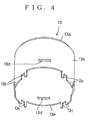
- two rectangular engaging openings 13d and 13d are formed in the peripheral wall of the yoke body 13, as shown in Fig.4.
- the engaging openings 13d and 13d are arranged to oppose each other across a central axis of the yoke body 13.
- a lower end 13e of the yoke body 13 is provided with downwardly projecting protrusions 13f which are adapted to be capable of locking the bearing housing 15.
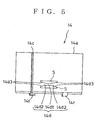
- the auxiliary yoke 14 has a slit 14c extending from an upper edge 14a to a lower edge 14b to enlarge peripherally.
- the auxiliary yoke 14 has an elasticity so that the auxiliary yoke can be enlarged peripherally by the slit 14c while can be reduced in the original shape by the elasticity.
- At least one deformable band is provided in the other of the peripheral walls of the yoke body 13 and auxiliary yoke 14 to engage in the least one engaging opening.
- two deformable bands 14d are formed on the peripheral wall of the auxiliary yoke 14 to engage in the engaging openings 13d. These deformable bands 14d are arranged to oppose each other across a central axis of the auxiliary yoke 14.
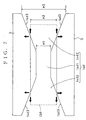
- Each of the deformable bands 14d is formed between a pair of adjacent trapezoidal cutouts S and S and has a elongated rectangular central bridged portion 14d1 and a pair of trapezoidal portions 14d2 and 14d2 which are arranged in right and left sides of the central bridged portion as viewed from Fig, 7.
- each deformable band 14d has an elasticity and is deformable to insert in and remove from the corresponding engaging opening 13d.
- a width H1 of each of the central bridged portions 14d1 is less than a width H2 of the engaging opening 13d.
- each deformable band 14d is large than the width H2 of the corresponding engaging opening 13d.
- Inclined surfaces 14d3 are provided on the both sides of the central bridged portion 14d1 to form the trapezoidal portions 14d2.
- the opposed inclined surfaces on each side of the central bridged portion are set to widen a space between the opposed inclined surfaces according to go away from the central bridged portion.
- each deformable band 14d is provided with a set of inclined surfaces 14d3 which is arranged on each side of the central bridged portion 14d1.
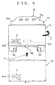
- a lower edge 14b of the auxiliary yoke 14 is provided with stoppers 14f and 14f arranged to oppose each other across the central axis of the auxiliary yoke, as shown in Fig. 9.
- Each of the stoppers 14f has a L-letter shape which a vertical portion extending downwardly from the a lower end of the auxiliary yoke 14 and a horizontal portion extending from a lower end of the vertical portion to the central axis of the auxiliary yoke.
- the stoppers stop the movement of the auxiliary yoke 14 by abutment of the stoppers with the lower end 13e of the yoke body 13.
- the auxiliary yoke 14 is rotated relative to the yoke body 13 in a direction as shown by arrow Z in Fig. 9, it is rotated by sliding between the stoppers 14f and the lower end of the 13e of the yoke body 13 and then the stoppers are abutted with the protrusions 13f to stop the rotation of the auxiliary yoke 14.
- the deformable bands 14d are disposed to face to the engaging openings 13.
- the electric motor 10 is configured in such a manner that the auxiliary yoke 14 is fitted on the yoke body 13 in such a manner that the central bridged portions 14d1 are inserted into the engaging openings 13d, respectively and inclined surfaces 14d3 press the edges of the engaging openings 13d (see Fig.1)
- the bearing housing 15 is engaged with the protrusions 13f of the yoke body 13.
- the rotational driving shaft 16 is rotatably supported by bearings 17 and 17 provided in central parts of the bottom 13a of the yoke body 13 and bearing housing 15.
- the rotor 18 is fixed on an intermediate part of the rotational driving shaft 16.
- the rotor 18 is composed of a core 18a made of laminated steel plates, a plurality of slots 18b provided peripherally of an outer peripheral wall of the core 18a and coils 18c wound around the slots.
- a commutator 19 is attached on the rotational driving shaft 16 between the rotor 18 and bearing housing 15 to pass an electrical power to the coils 18c.
- two blush holders 20 Disposed to face the commutator 19 are two blush holders 20 which are made of an insulting material such as plastic resin.
- the blush holders are connected with a blush substrate (not shown).
- a brush 21 is disposed within each of the brush holders 20 to be movable radially of a yoke 12.
- the brush 21 is electrically connected with a coupler terminal (not shown) provided on an outer peripheral wall of each yoke 12.
- Each brush 21 is biased toward the commutator 19 by a spring 20a supported in each of the brush holders 20 to contact resiliently an inner end of the brush 21 with an outer peripheral wall of the commutator 19.
- the mounting bracket 22 has a cylindrical bracket body 22a in which the yoke 12 is fitted, a bottom 22b and a flange 22c extending radially from the bracket body 22a.
- the electric motor 10 can be fixed to the mounting object by fixing the flange 22c to the mounting object.
- bracket body 22a is provided with a hole 22d for communicating with the air suction hole 15a of the bearing housing 15.
- the permanent magnets 11 and 11 are first held on the inner peripheral wall of the yoke body 13 and then the auxiliary yoke 14 is fitted on the outer peripheral wall of the yoke body 13 by matching the upper edge 14a of the auxiliary yoke with the lower end 13e of the yoke body 13 and sliding upwardly the auxiliary yoke 14 along the outer peripheral wall of the yoke body 13 as shown in Fig. 9.
- the upper movement of the auxiliary yoke 14 is stopped by the abutment of the stoppers 14f of the auxiliary yoke 14 with the lower end 13e of the yoke body 13.
- the auxiliary yoke 14 is then rotated relative to the yoke body 13 in the direction as shown by the arrow Z in Fig. 9.
- the stoppers 14f are abutted with the protrusions 13f of the yoke body 13 as shown in Figs. 10 and 12 to stop the rotation of the auxiliary yoke 14 relative to the yoke body 13.
- the deformable bands 14d of the auxiliary yoke 14 are arranged to face the engaging openings 13d of the yoke body 13 and at least the central bridged portion 14d1 of each of the deformable bands 14 is inserted or snapped into the corresponding engaging openings 13d to prevent the auxiliary yoke 14 from rotating and moving axially relative to the yoke body 13.
- auxiliary yoke has an elasticity and the slit 14c, even though the deformable bands are projected inwardly of the auxiliary yoke, a scratch or the like does not occur on the yoke body.
- the deformable bands are faced the engaging openings
- the deformable bands especially the central bridged portions are deformed to insert into the engaging openings.
- the inclined surfaces are also pressed against the edges of the engaging openings.
- the auxiliary yoke 14 is locked certainly on the yoke body 13. In this embodiment, it is not necessary that the auxiliary yoke 14 has the aforementioned structure for enlarging peripherally.
- the upper two inclined surfaces 14d3 in each deformable opening 14d are pressed upward and rightward and leftward as shown by the arrows in Fig. 7 on the upper edge of the engaging opening 13d, and the lower two inclined surfaces 14d3 are pressed downward and rightward and leftward as shown by the arrows in Fig. 7 on the lower edge of the engaging opening 13d.
- each deformable band 14 is locked certainly on the yoke body 13 without being moved relative to the yoke body. This is accomplished by only inserting each of the deformable bands 14d provided in the auxiliary yoke 14 into each of the engaging openings 13d provided in the yoke body 13 by rotating relatively the auxiliary yoke and yoke body.
- a second embodiment of the present invention is shown.
- the similar numerals are attached to the similar parts as in the first embodiment.
- each of deformable bands 114d is shown in Fig. 15.
- the deformable band 114d is formed between an upper elongate rectangular cutout S1 and a lower trapezoidal cutout S2 as shown in Fig. 15.
- the deformable band 114d has a lower part having the inclined surfaces 14d3 and 14d3 similar to that in the first embodiment, which are symmetrical in right and left, as viewed from Fig. 15, and an upper part formed from a straight surface 115.
- deformable bands 114d are the same as that in the deformable bands 14d in the first embodiment.
- the auxiliary yoke 14 When the deformable bands 114d are inserted into the engaging openings 13d, the auxiliary yoke 14 is no moved relative to the yoke body 13. Further, the edges of the engaging openings 13d are pressed downward and rightward and leftward as shown by arrows in Fig. 15 by means of the inclined surfaces 14d to prevent the auxiliary yoke 14 from moving peripherally thereby locking further certainly the axial and peripheral movements of the auxiliary yoke 14 relative to the yoke body 13.
- the stoppers 14f of the auxiliary yoke 14 are abutted with the lower end of the yoke body 13 and therefore the auxiliary yoke 14 does not move upwardly relative to the yoke body.
- the auxiliary yoke 14 is locked certainly to the yoke body 13 only by inserting the deformable bands 114d of the auxiliary yoke 14 into the engaging openings 13d of the yoke body 13.
- FIG. 16 a third embodiment of the present invention is shown.
- the electric motor 10 has deformable bands 214d each of which is formed between the same upper elongate rectangular cutout S1 as in the second embodiment and a lower cutout S3, as shown in Fig. 16.
- the lower cutout S3 has a right straight surface and a left inclined surface as viewed in Fig. 16.
- each deformable band 214d has a lower part having an inclined surface 214d3 and a straight surface 216 and an upper part formed from a straight surface 215.
- deformable bands 214d are the same as that in the deformable bands 14d and 114d in the first and second embodiments.
- the auxiliary yoke 14 When the deformable bands 214d are inserted into the engaging openings 13d, the auxiliary yoke 14 is no moved relative to the yoke body 13. Further, the edges of the engaging openings 13d are pressed downward and leftward as shown by arrows in Fig. 16 by means of the inclined surfaces 214d3 to prevent the auxiliary yoke 14 from moving peripherally thereby locking further certainly the axial and peripheral movements of the auxiliary yoke 14 relative to the yoke body 13.
- the auxiliary yoke 14 is locked certainly to the yoke body 13 only by inserting the deformable bands 214d of the auxiliary yoke 14 into the engaging openings 13d of the yoke body 13.
- the present invention is not limited to these embodiments.
- two sets of the deformable bands and engaging openings have been provided on the yoke, but, one set or three sets of the deformable bands and engaging openings may be provided on the yoke.
- a shape and a size of the deformable bands and engaging openings are also not limited to that in the above embodiments.
Landscapes
- Engineering & Computer Science (AREA)
- Power Engineering (AREA)
- Motor Or Generator Frames (AREA)
- Permanent Field Magnets Of Synchronous Machinery (AREA)
- Dc Machiner (AREA)
Abstract
Description
- The present invention relates to a case and an electric motor which is used to rotate a blower fan in an air conditioner for an automobile for carrying out cooling and heating in a passenger room of the automobile, for example, and a method for producing the electric motor.
- In general, there is known a case having an outer cylindrical member and an inner cylindrical member fitted in the outer cylindrical member.
- A lock means is required to lock the inner and outer cylindrical members. Conventionally, the lock means is complicate in structure and an operation for locking is not easy.
- On the other hand, there is known an
electric motor 1 as shown in Fig. 17 (see, for example, Japanese Patent Laid-Open No. 4-190646,pages 1 to 2, Fig. 2). - The
electric motor 1 includespermanent magnets 2 for generating a magnetic flux and acylindrical yoke 3 or a case on whose inner peripheral wall thepermanent magnets 2 is held. - The
yoke 3 has an inner cylindrical member or a cylindrical yoke body 4 having a bottom and an outer cylindrical member or anauxiliary yoke 5 fitted in an inner peripheral wall of the yoke body 4. - The
auxiliary yoke 5 is mainly formed by a pressed-processing to have a thin wall thickness and is used to conduct an attenuation of a magnetic flux leaked from the yoke body 4. - The
auxiliary yoke 5 has also at an outer peripheral wall thereof aslit 5c extending from one end, anupper end 5a to the other end, alower end 5b to enlarge peripherally theauxiliary yoke 5, as shown in Fig. 18. - The
auxiliary yoke 5 is enlarged peripherally by provision of theslit 5c and fitted on the yoke body 4 to surround it. In other words, the yoke body 4 is inserted into theauxiliary yoke 5. - In addition, the
auxiliary yoke 5 is provided withslits 5d which are opened at the upper andlower ends auxiliary yoke 5, respectively to eliminate a leaked magnetic flux in theelectric motor 1. - There is also known an electric motor that a cylindrical auxiliary yoke is fixed to a cylindrical yoke body by press-fitting the yoke body into the auxiliary yoke or welding them (see, for example, Japanese Patent No. 2793653, page 4, Fig. 3).
- However, in each of the aforementioned electro motors, there is a problem that a position of the auxiliary yoke is not stable by it being moving on the yoke body 4 since the
auxiliary yoke 5 holds merely the yoke body 4. - Further, the position of the auxiliary yoke is not necessarily stable even though the yoke body is press-fitted in the auxiliary yoke and if the auxiliary yoke is welded to the yoke body, processes of assembling the auxiliary yoke and yoke body are increased because of addition of a welding process.
- Under such circumstances, it is considered that an
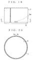
auxiliary yoke 7 is fixed to ayoke body 6, for example, by engagement of an engagedpiece 7a provided on theauxiliary yoke 7 into an engagedopening 6a provided in theyoke body 6, as shown in Figs. 19 and 20. - However, in the structure, there is a possibility that the engaged
piece 7a slides under a pressure on the outer peripheral wall of theyoke body 6 until it reaches theengaging opening 6a to thus form a scratch on the peripheral wall of the yoke body. - The present invention is made in view of the above problems and it is, therefore, an object of the present invention to provide a case and an electric motor and a method for producing the electric motor, capable of assembling easily.
- To accomplish the object, a case according to a first aspect of the present invention comprises an outer cylindrical member, an inner cylindrical member fitted in the outer cylindrical member, at least one engaging opening provided in one of the outer and inner cylindrical members, a deformable band provided in the other of the outer and inner cylindrical members for inserting into the engaging opening and a poisoning mechanism provided on the outer and inner cylindrical members to face the deformable band to the engaging opening.
- In one embodiment, the positioning mechanism includes a stopper provided on one of the outer and inner cylindrical members to contact with a portion of the other of the outer and inner cylindrical members and a protrusion provided on the other of the outer and inner cylindrical members to contact with the stopper.
- An electric motor according to a second aspect of the present invention comprises a yoke in which permanent magnets are held, the yoke including a cylindrical yoke body having a bottom and an auxiliary yoke in which the yoke body is fitted, at least one engaging opening provided in one of the yoke body and auxiliary yoke and a deformable band provided in the other of the yoke body and auxiliary yoke.
- The deformable band is fitted in the engaging opening in a state that the yoke body and auxiliary yoke are fitted.
- In this case, a positioning mechanism is provided between the yoke body and auxiliary yoke to face the deformable band to the engaging opening.
- The deformable band is provided with a plurality of inclined surfaces adapted to contact with edges of the engaging opening to impart a pressed force axially and peripherally of the yoke body or auxiliary yoke.
- The above and other objects, features and advantages of the present invention will become more apparent from the following description taken in connection with the accompanying drawings, in which:
- Fig. 1 is a sectional view showing an electric motor according to a first embodiment of the present invention.
- Fig. 2 is a side view of a yoke body in the electric motor.
- Fig. 3 is a bottom view of the yoke body.
- Fig. 4 is a perspective view of the yoke body.
- Fig. 5 is a side view of an auxiliary yoke in the electric motor.
- Fig. 6 is a perspective view of the auxiliary yoke.
- Fig. 7 is an operational view showing a state that deformable bands according to the present invention impart a pressed force to edges of an engaging opening.
- Fig. 8 is a bottom view of the auxiliary yoke.
- Fig. 9 is an explanatory view showing a process of assembling the electric motor.
- Fig. 10 is a bottom view of a yoke in the electric motor.
- Fig. 11 is a side view of the yoke.
- Fig. 12 is a sectional view of the yoke taken along the line A-A in Fig. 10.
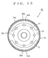
- Fig. 13 is a sectional view of the yoke taken along the line B-B in Fig. 11.
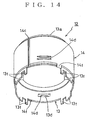
- Fig. 14 is a perspective view of the yoke.
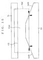
- Fig.15 is a side view of a yoke in a second embodiment.
- Fig. 16 is a side view of a yoke in a third embodiment.
- Fig. 17 is a sectional view of a first conventional electric motor.
- Fig. 18 is a perspective view of an auxiliary yoke in the first conventional electric motor.
- Fig. 19 is a side view of a second conventional electric motor.
- Fig. 20 is a sectional view taken along the line C-C in Fig. 19.
-
- Some embodiments of the present invention will be explained with reference to the accompanying drawings below.
- A first embodiment of an
electric motor 10 according to the present invention will be first described referring to Figs. 1 to 13. As shown in Fig.1, theelectric motor 10 is mainly composed of a pair ofpermanent magnets cylindrical yoke 12 on aninside wall 12 of which the permanent magnets are held, a bearinghousing 15 disposed to cover a lower opening of theyoke 12, arotational driving shaft 16 passing through a center of theyoke 12, arotor 18 fixed in a periphery of a middle part of therotational driving shaft 16 and amounting bracket 22 to fix theyoke 12 and bearinghousing 15 to a mounting object such as a panel. - The
permanent magnets yoke 12 and held to oppose each other. - The
yoke 12 includes acylindrical yoke body 13 which has at one end (an upper end in Fig. 1) abottom 13a which is attached integrally to the body and a cylindricalauxiliary yoke 14 fitted in aperipheral wall 13b of theyoke body 13. - As shown in Fig. 2, the
bottom 13a of theyoke body 13 has a substantially conical shape as viewed from a side surface. - As shown in Fig. 3, a plurality of
exhaust holes 13c are arranged with a constant space respectively in the same distance from a center of thebottom 13a to exhaust air for cooling. A portion of the bearinghousing 15 is provided with anair suction hole 15a for supplying the air for cooling within theyoke 12. A central part of thebottom 13a is projected downwardly in an inverted hat-like shape, as shown in Fig. 1. - It is noted that at least one engaging opening is provided in one of peripheral walls of the
yoke body 13 andauxiliary yoke 14. In this embodiment, two rectangularengaging openings yoke body 13, as shown in Fig.4. Theengaging openings yoke body 13. - A
lower end 13e of theyoke body 13 is provided with downwardly projectingprotrusions 13f which are adapted to be capable of locking the bearinghousing 15. As shown in Figs. 5 and 6, theauxiliary yoke 14 has a slit 14c extending from anupper edge 14a to alower edge 14b to enlarge peripherally. Theauxiliary yoke 14 has an elasticity so that the auxiliary yoke can be enlarged peripherally by the slit 14c while can be reduced in the original shape by the elasticity. - Further, at least one deformable band is provided in the other of the peripheral walls of the
yoke body 13 andauxiliary yoke 14 to engage in the least one engaging opening. In this embodiment, twodeformable bands 14d are formed on the peripheral wall of theauxiliary yoke 14 to engage in the engagingopenings 13d. Thesedeformable bands 14d are arranged to oppose each other across a central axis of theauxiliary yoke 14. Each of thedeformable bands 14d is formed between a pair of adjacent trapezoidal cutouts S and S and has a elongated rectangular central bridged portion 14d1 and a pair of trapezoidal portions 14d2 and 14d2 which are arranged in right and left sides of the central bridged portion as viewed from Fig, 7. - The central bridged portion 14d1 in each
deformable band 14d has an elasticity and is deformable to insert in and remove from the corresponding engagingopening 13d. - A width H1 of each of the central bridged portions 14d1 is less than a width H2 of the
engaging opening 13d. - Further, the maximum width H3 of each
deformable band 14d is large than the width H2 of the corresponding engagingopening 13d. - Inclined surfaces 14d3 are provided on the both sides of the central bridged portion 14d1 to form the trapezoidal portions 14d2. The opposed inclined surfaces on each side of the central bridged portion are set to widen a space between the opposed inclined surfaces according to go away from the central bridged portion. In other words, each
deformable band 14d is provided with a set of inclined surfaces 14d3 which is arranged on each side of the central bridged portion 14d1. - Consequently, when the central bridged portion 14d1 of each deformable band is inserted into the corresponding engaging
opening 13d, the engagement of the central bridged portion and engaging opening is held and the four inclined surfaces 14d3 are adapted to impart a pressed force to edges of theengaging opening 13d by means of the elasticity occurred by the slit 14c of theauxiliary yoke 14. - Further, a
lower edge 14b of theauxiliary yoke 14 is provided withstoppers stoppers 14f has a L-letter shape which a vertical portion extending downwardly from the a lower end of theauxiliary yoke 14 and a horizontal portion extending from a lower end of the vertical portion to the central axis of the auxiliary yoke. When theauxiliary yoke 14 is moved on theperipheral wall 13b of theyoke body 13 in an upper direction as shown by arrow Y in Fig. 9, the stoppers stop the movement of theauxiliary yoke 14 by abutment of the stoppers with thelower end 13e of theyoke body 13. When theauxiliary yoke 14 is rotated relative to theyoke body 13 in a direction as shown by arrow Z in Fig. 9, it is rotated by sliding between thestoppers 14f and the lower end of the 13e of theyoke body 13 and then the stoppers are abutted with theprotrusions 13f to stop the rotation of theauxiliary yoke 14. - When the
stoppers 14f are abutted with theprotrusions 13f of theyoke body 13, thedeformable bands 14d are disposed to face to the engagingopenings 13. - In this way, the
electric motor 10 is configured in such a manner that theauxiliary yoke 14 is fitted on theyoke body 13 in such a manner that the central bridged portions 14d1 are inserted into the engagingopenings 13d, respectively and inclined surfaces 14d3 press the edges of the engagingopenings 13d (see Fig.1) - The bearing
housing 15 is engaged with theprotrusions 13f of theyoke body 13. - The
rotational driving shaft 16 is rotatably supported bybearings yoke body 13 and bearinghousing 15. - The
rotor 18 is fixed on an intermediate part of therotational driving shaft 16. Therotor 18 is composed of acore 18a made of laminated steel plates, a plurality ofslots 18b provided peripherally of an outer peripheral wall of thecore 18a and coils 18c wound around the slots. - Further, a
commutator 19 is attached on therotational driving shaft 16 between therotor 18 and bearinghousing 15 to pass an electrical power to thecoils 18c. Disposed to face thecommutator 19 are twoblush holders 20 which are made of an insulting material such as plastic resin. The blush holders are connected with a blush substrate (not shown). Abrush 21 is disposed within each of thebrush holders 20 to be movable radially of ayoke 12. Thebrush 21 is electrically connected with a coupler terminal (not shown) provided on an outer peripheral wall of eachyoke 12. - Each
brush 21 is biased toward thecommutator 19 by a spring 20a supported in each of thebrush holders 20 to contact resiliently an inner end of thebrush 21 with an outer peripheral wall of thecommutator 19. - The mounting
bracket 22 has acylindrical bracket body 22a in which theyoke 12 is fitted, a bottom 22b and aflange 22c extending radially from thebracket body 22a. Theelectric motor 10 can be fixed to the mounting object by fixing theflange 22c to the mounting object. - In addition, the
bracket body 22a is provided with ahole 22d for communicating with theair suction hole 15a of the bearinghousing 15. - Subsequently, an assembled method of the electric motor as described above will be explained below.
- The
permanent magnets yoke body 13 and then theauxiliary yoke 14 is fitted on the outer peripheral wall of theyoke body 13 by matching theupper edge 14a of the auxiliary yoke with thelower end 13e of theyoke body 13 and sliding upwardly theauxiliary yoke 14 along the outer peripheral wall of theyoke body 13 as shown in Fig. 9. The upper movement of theauxiliary yoke 14 is stopped by the abutment of thestoppers 14f of theauxiliary yoke 14 with thelower end 13e of theyoke body 13. - The
auxiliary yoke 14 is then rotated relative to theyoke body 13 in the direction as shown by the arrow Z in Fig. 9. During the rotation of theauxiliary yoke 14, thestoppers 14f are abutted with theprotrusions 13f of theyoke body 13 as shown in Figs. 10 and 12 to stop the rotation of theauxiliary yoke 14 relative to theyoke body 13. At this time, thedeformable bands 14d of theauxiliary yoke 14 are arranged to face the engagingopenings 13d of theyoke body 13 and at least the central bridged portion 14d1 of each of thedeformable bands 14 is inserted or snapped into the corresponding engagingopenings 13d to prevent theauxiliary yoke 14 from rotating and moving axially relative to theyoke body 13. - In this case, since the auxiliary yoke has an elasticity and the slit 14c, even though the deformable bands are projected inwardly of the auxiliary yoke, a scratch or the like does not occur on the yoke body.
- Alternatively, when the deformable bands are faced the engaging openings, when a worker presses the deformable bands to insert them into the engaging openings, the deformable bands, especially the central bridged portions are deformed to insert into the engaging openings. At this time, the inclined surfaces are also pressed against the edges of the engaging openings. As a result, the
auxiliary yoke 14 is locked certainly on theyoke body 13. In this embodiment, it is not necessary that theauxiliary yoke 14 has the aforementioned structure for enlarging peripherally. In addition, since the deformable bands are not projected inwardly of the auxiliary yoke at an initial step, even though the auxiliary yoke is rotated on the yoke body, a scratch or the like does not occur on the yoke body. - In the aforementioned first embodiment, because the
electric motor 10 has the four inclined surfaces 14d3, these four inclined surfaces in eachdeformable band 14 d are pressed on the edges of each of the engagingopenings 13d. - More specifically, as shown in Fig. 7, the upper two inclined surfaces 14d3 in each
deformable opening 14d are pressed upward and rightward and leftward as shown by the arrows in Fig. 7 on the upper edge of theengaging opening 13d, and the lower two inclined surfaces 14d3 are pressed downward and rightward and leftward as shown by the arrows in Fig. 7 on the lower edge of theengaging opening 13d. - In this way, because the four inclined surfaces 14d3 in each
deformable band 14 are adapted to impart a pressed force on the edges of theengaging opening 13d in axial and peripheral directions of theyoke body 13, theauxiliary yoke 14 is locked certainly on theyoke body 13 without being moved relative to the yoke body. This is accomplished by only inserting each of thedeformable bands 14d provided in theauxiliary yoke 14 into each of the engagingopenings 13d provided in theyoke body 13 by rotating relatively the auxiliary yoke and yoke body. - In addition, when the
auxiliary yoke 14 is locked on theyoke body 13, and theelectric motor 10 is attached through the mountingbracket 22 to the mounting object, even during driving of the electric motor, theyoke body 13 is not moved within theauxiliary yoke 14 to maintain a stability of the assembled electric motor. - In the aforementioned electric motor, when the
stoppers 14f are contacted with theprotrusions 13f, thedeformable bands 14d are faced to the engagingopenings 13d and therefore it is very easy to fit the deformable bands in the engaging openings. - Referring to Fig. 15, a second embodiment of the present invention is shown. In the second embodiment, the similar numerals are attached to the similar parts as in the first embodiment.
- In the embodiment, a configuration of each of
deformable bands 114d is shown in Fig. 15. In the configuration, thedeformable band 114d is formed between an upper elongate rectangular cutout S1 and a lower trapezoidal cutout S2 as shown in Fig. 15. As a result of the cutouts, thedeformable band 114d has a lower part having the inclined surfaces 14d3 and 14d3 similar to that in the first embodiment, which are symmetrical in right and left, as viewed from Fig. 15, and an upper part formed from astraight surface 115. - An arrangement and so on of the
deformable bands 114d are the same as that in thedeformable bands 14d in the first embodiment. - When the
deformable bands 114d are inserted into the engagingopenings 13d, theauxiliary yoke 14 is no moved relative to theyoke body 13. Further, the edges of the engagingopenings 13d are pressed downward and rightward and leftward as shown by arrows in Fig. 15 by means of theinclined surfaces 14d to prevent theauxiliary yoke 14 from moving peripherally thereby locking further certainly the axial and peripheral movements of theauxiliary yoke 14 relative to theyoke body 13. - More specifically, when the
inclined surfaces 14d impart downwardly a pressed force to the edges of the engaging openings, there is a possibility that an energized force is imparted to theauxiliary yoke 14,which tends to move upwardly (as viewed in Fig. 15) theyoke body 13. - However, at this time, the
stoppers 14f of theauxiliary yoke 14 are abutted with the lower end of theyoke body 13 and therefore theauxiliary yoke 14 does not move upwardly relative to the yoke body. - In the electric motor in the embodiment, the
auxiliary yoke 14 is locked certainly to theyoke body 13 only by inserting thedeformable bands 114d of theauxiliary yoke 14 into the engagingopenings 13d of theyoke body 13. - Referring to Fig. 16, a third embodiment of the present invention is shown.
- In Fig. 16, the similar numerals are attached to the similar parts as in the first and second embodiments.
- In the embodiment, the
electric motor 10 hasdeformable bands 214d each of which is formed between the same upper elongate rectangular cutout S1 as in the second embodiment and a lower cutout S3, as shown in Fig. 16. The lower cutout S3 has a right straight surface and a left inclined surface as viewed in Fig. 16. As a result of the cutouts, eachdeformable band 214d has a lower part having an inclined surface 214d3 and astraight surface 216 and an upper part formed from astraight surface 215. - An arrangement and the other structure of the
deformable bands 214d are the same as that in thedeformable bands - When the
deformable bands 214d are inserted into the engagingopenings 13d, theauxiliary yoke 14 is no moved relative to theyoke body 13. Further, the edges of the engagingopenings 13d are pressed downward and leftward as shown by arrows in Fig. 16 by means of the inclined surfaces 214d3 to prevent theauxiliary yoke 14 from moving peripherally thereby locking further certainly the axial and peripheral movements of theauxiliary yoke 14 relative to theyoke body 13. - The other operation of the
deformable bands 214d is the same as in the second embodiment. - In the electric motor in the embodiment, the
auxiliary yoke 14 is locked certainly to theyoke body 13 only by inserting thedeformable bands 214d of theauxiliary yoke 14 into the engagingopenings 13d of theyoke body 13. - As described above, according to the present invention, it is possible to prevent the auxiliary yoke from removing relative to the yoke body by means of a easy operation.
- Although the various embodiments have been explained, the present invention is not limited to these embodiments. For example, in the aforementioned embodiments, two sets of the deformable bands and engaging openings have been provided on the yoke, but, one set or three sets of the deformable bands and engaging openings may be provided on the yoke.
- A shape and a size of the deformable bands and engaging openings are also not limited to that in the above embodiments.
Claims (10)
- A case comprising:characterized in that,an outer cylindrical member (14) ; andan inner cylindrical member (13) fitted in said outer cylindrical member;
at least one engaging opening (13d) is provided in one of said inner and outer cylindrical members;
a deformable band (14d) is provided in the other of said inner and outer cylindrical members for inserting into said engaging opening; and
a poisoning mechanism (13f, 14f) is provided between said inner and outer cylindrical members to face said deformable band (14d) to said engaging opening (13d). - The case according to claim 1, characterized in that said positioning mechanism has a stopper (14f) provided on one of said inner and outer cylindrical members (13, 14) to contact with the other of the inner and outer cylindrical members (13, 14) and a protrusion (13f) provided on the other of said inner and outer cylindrical members to contact with said stopper.
- An electric motor comprising:characterized in that,a yoke (12) in which permanent magnets (11, 11) are held,said yoke (12) including a cylindrical yoke body (13) having a bottom (13a) and an auxiliary yoke (14) in which said yoke body is fitted,
at least one engaging opening (13d) is provided in one of said yoke body and auxiliary yoke,
a deformable band (14d) is provided in the other of said yoke body and auxiliary yoke, and
said deformable band (14d) is fitted in said engaging opening (13d) in a state that said yoke body (13) and auxiliary yoke (14) are fitted. - The electrical motor according to claim 3, characterized in that it further comprises a positioning mechanism (13f, 14f) provided between said yoke body (13) and auxiliary yoke (14) to face the deformable band (14d) to the engaging opening (13d).
- The electric motor according to claim 4, characterized in that said positioning mechanism includes a stopper (14f) provided on the auxiliary yoke (14) to contact with a portion of the yoke body (13) and a protrusion (13f) provided on the yoke body (13) to contact with said stopper (14f).
- The electric motor according to claim 1, characterized in that said deformable band (14d) includes a plurality of inclined surfaces (14d3) which are contacted with edges of said engaging opening (13d) to impart a pressed force axially and peripherally of the inner or outer cylindrical member.
- The electric motor according to claim 3, characterized in that said deformable band (14d) includes a plurality of inclined surfaces (14d3) which are contacted with edges of said engaging opening (13d) to impart a pressed force thereto axially and peripherally of the yoke body (13) or auxiliary yoke (14).
- The case according to claim 2, characterized in that said deformable band (14d) includes inclined surfaces (14d3) which are contacted with the edges of the engaging opening (13d) to impart a pressed force thereto so as to contact the stopper with the other of the inner and outer cylindrical members (13,14).
- The electric motor according to claim 5, characterized in that said deformable band (14d) includes inclined surfaces which are contacted with the edges of the engaging opening (13d) to impart thereto a pressed force so as to contact the stopper (14f) with the yoke body (13).
- A method for producing an electric motor, characterized in that it comprises the steps of:fitting a cylindrical yoke body (13) into a cylindrical auxiliary yoke (14);rotating said auxiliary yoke (14) relative to said yoke body (13);facing a deformable band (14d) provided on one of said auxiliary yoke (14) and yoke body (13) to an engaging opening (13d) provided on the other of said auxiliary yoke (14) and yoke body (13) by abutting a stopper (14f) provided on one of said auxiliary yoke (14) and yoke body (13) with a protrusion (13f) provided on the other of the auxiliary yoke and yoke body; andinserting said deformable band (14d) into said engaging opening (13d).
Applications Claiming Priority (2)
| Application Number | Priority Date | Filing Date | Title |
|---|---|---|---|
| JP2002269411 | 2002-09-17 | ||
| JP2002269411A JP3953923B2 (en) | 2002-09-17 | 2002-09-17 | Electric motor and method for manufacturing electric motor |
Publications (2)
| Publication Number | Publication Date |
|---|---|
| EP1401086A1 true EP1401086A1 (en) | 2004-03-24 |
| EP1401086B1 EP1401086B1 (en) | 2006-12-20 |
Family
ID=31944510
Family Applications (1)
| Application Number | Title | Priority Date | Filing Date |
|---|---|---|---|
| EP03020973A Expired - Lifetime EP1401086B1 (en) | 2002-09-17 | 2003-09-16 | Case, electric motor and method for producing the electric motor |
Country Status (4)
| Country | Link |
|---|---|
| US (1) | US6984905B2 (en) |
| EP (1) | EP1401086B1 (en) |
| JP (1) | JP3953923B2 (en) |
| DE (1) | DE60310489T2 (en) |
Families Citing this family (10)
| Publication number | Priority date | Publication date | Assignee | Title |
|---|---|---|---|---|
| JP3953923B2 (en) * | 2002-09-17 | 2007-08-08 | カルソニックカンセイ株式会社 | Electric motor and method for manufacturing electric motor |
| DE112004002423D2 (en) * | 2003-10-10 | 2006-08-24 | Bosch Gmbh Robert | electric motor |
| US7358634B2 (en) * | 2005-05-31 | 2008-04-15 | Regal-Beloit Corporation | Enclosure for an electric motor that incorporates a mid shield |
| JP4822770B2 (en) * | 2005-08-29 | 2011-11-24 | 株式会社ミツバ | Method of manufacturing motor having motor and double yoke |
| JP2008035663A (en) * | 2006-07-31 | 2008-02-14 | Asmo Co Ltd | Vehicle air-conditioning motor |
| DE102006058064A1 (en) * | 2006-12-07 | 2008-06-19 | Ipgate Ag | Electric induction machine |
| WO2008121126A1 (en) | 2007-03-30 | 2008-10-09 | Summerton James E | Non-peptidic molecules for detecting and treating tumors |
| US8552605B2 (en) * | 2010-02-02 | 2013-10-08 | Asmo Co., Ltd. | Dynamo-electric machine |
| CN202978514U (en) * | 2012-11-29 | 2013-06-05 | 中山大洋电机制造有限公司 | An assembly structure of motor end cover and casing |
| DE102017217619A1 (en) | 2017-10-04 | 2019-04-04 | Bühler Motor GmbH | Electronically commutated DC motor |
Citations (9)
| Publication number | Priority date | Publication date | Assignee | Title |
|---|---|---|---|---|
| US3234414A (en) * | 1962-03-26 | 1966-02-08 | Philips Corp | Miniature electric motor |
| US4335323A (en) * | 1980-01-17 | 1982-06-15 | Ambac Industries, Incorporated | Stamped sheet metal frame for dynamoelectric machine |
| JPS59201644A (en) * | 1983-04-28 | 1984-11-15 | Toshiba Corp | Stator core of rotary electric machine |
| US4548334A (en) * | 1983-01-26 | 1985-10-22 | Itt Industries, Inc. | Electric motor housing with end cap |
| JPH02273046A (en) * | 1989-04-14 | 1990-11-07 | Matsushita Electric Ind Co Ltd | permanent magnet motor |
| JPH0398434A (en) * | 1989-09-08 | 1991-04-24 | Hitachi Ltd | Miniature motor |
| JPH04190646A (en) * | 1990-11-22 | 1992-07-09 | Matsushita Electric Ind Co Ltd | Auxiliary yoke |
| JPH06245452A (en) * | 1993-02-22 | 1994-09-02 | Copal Co Ltd | Back yoke for dc motor magnet and its manufacture |
| US6359363B1 (en) * | 1998-07-28 | 2002-03-19 | Robert Bosch Gmbh | Commutator-small power motor |
Family Cites Families (3)
| Publication number | Priority date | Publication date | Assignee | Title |
|---|---|---|---|---|
| JP3100707B2 (en) * | 1990-11-28 | 2000-10-23 | デイナミート ノーベル アクチエンゲゼルシヤフト | Gas generator for inflatable collision cushion |
| DE19861024A1 (en) * | 1998-02-28 | 1999-09-09 | Bosch Gmbh Robert | Electric motor |
| JP3953923B2 (en) * | 2002-09-17 | 2007-08-08 | カルソニックカンセイ株式会社 | Electric motor and method for manufacturing electric motor |
-
2002
- 2002-09-17 JP JP2002269411A patent/JP3953923B2/en not_active Expired - Fee Related
-
2003
- 2003-08-29 US US10/651,101 patent/US6984905B2/en not_active Expired - Lifetime
- 2003-09-16 DE DE60310489T patent/DE60310489T2/en not_active Expired - Lifetime
- 2003-09-16 EP EP03020973A patent/EP1401086B1/en not_active Expired - Lifetime
Patent Citations (9)
| Publication number | Priority date | Publication date | Assignee | Title |
|---|---|---|---|---|
| US3234414A (en) * | 1962-03-26 | 1966-02-08 | Philips Corp | Miniature electric motor |
| US4335323A (en) * | 1980-01-17 | 1982-06-15 | Ambac Industries, Incorporated | Stamped sheet metal frame for dynamoelectric machine |
| US4548334A (en) * | 1983-01-26 | 1985-10-22 | Itt Industries, Inc. | Electric motor housing with end cap |
| JPS59201644A (en) * | 1983-04-28 | 1984-11-15 | Toshiba Corp | Stator core of rotary electric machine |
| JPH02273046A (en) * | 1989-04-14 | 1990-11-07 | Matsushita Electric Ind Co Ltd | permanent magnet motor |
| JPH0398434A (en) * | 1989-09-08 | 1991-04-24 | Hitachi Ltd | Miniature motor |
| JPH04190646A (en) * | 1990-11-22 | 1992-07-09 | Matsushita Electric Ind Co Ltd | Auxiliary yoke |
| JPH06245452A (en) * | 1993-02-22 | 1994-09-02 | Copal Co Ltd | Back yoke for dc motor magnet and its manufacture |
| US6359363B1 (en) * | 1998-07-28 | 2002-03-19 | Robert Bosch Gmbh | Commutator-small power motor |
Non-Patent Citations (5)
| Title |
|---|
| PATENT ABSTRACTS OF JAPAN vol. 009, no. 065 (E - 304) 26 March 1985 (1985-03-26) * |
| PATENT ABSTRACTS OF JAPAN vol. 015, no. 029 (E - 1026) 23 January 1991 (1991-01-23) * |
| PATENT ABSTRACTS OF JAPAN vol. 015, no. 284 (E - 1091) 18 July 1991 (1991-07-18) * |
| PATENT ABSTRACTS OF JAPAN vol. 016, no. 513 (E - 1283) 22 October 1992 (1992-10-22) * |
| PATENT ABSTRACTS OF JAPAN vol. 018, no. 635 (E - 1638) 5 December 1994 (1994-12-05) * |
Also Published As
| Publication number | Publication date |
|---|---|
| US6984905B2 (en) | 2006-01-10 |
| DE60310489D1 (en) | 2007-02-01 |
| JP2004112880A (en) | 2004-04-08 |
| DE60310489T2 (en) | 2007-04-19 |
| JP3953923B2 (en) | 2007-08-08 |
| EP1401086B1 (en) | 2006-12-20 |
| US20040169428A1 (en) | 2004-09-02 |
Similar Documents
| Publication | Publication Date | Title |
|---|---|---|
| US8803390B2 (en) | Dynamo-electric machine | |
| US7671495B2 (en) | Armature and motor | |
| US5519574A (en) | Electronic component cooling apparatus | |
| US5510664A (en) | Brushless motor | |
| EP1401086B1 (en) | Case, electric motor and method for producing the electric motor | |
| US5444320A (en) | Electric motor with brush retainer | |
| EP1637403A1 (en) | Rotary connector | |
| KR20010108070A (en) | Dc motor | |
| KR20010113787A (en) | Electric drive, especially for motor vehicles | |
| JP3668676B2 (en) | Magnet holder, permanent magnet type rotating electrical machine including the same, and method of attaching permanent magnet | |
| JP2002142412A (en) | Electric motor | |
| JPH10336978A (en) | Motor manufacturing method and motor | |
| GB2302215A (en) | Hand machine tool electric motor | |
| JP2004336927A (en) | Apparatus and method for manufacturing motor rotor | |
| CN110858741A (en) | Motor with a stator having a stator core | |
| CN114788140A (en) | Brushless motor | |
| JP2003134718A (en) | motor | |
| CN112583170A (en) | Bus bar device, stator, and motor | |
| JP2010142103A (en) | Electric motor and method of assembling the same | |
| JP2024093453A (en) | Rotor, rotary electric machine, and manufacturing method of rotor | |
| JPH10336972A (en) | Rotating electric machine | |
| KR20230083621A (en) | Motor | |
| KR102938742B1 (en) | Motor | |
| JP3011597B2 (en) | Outer rotor type brushless DC motor | |
| JP7788333B2 (en) | Rotating electric machines |
Legal Events
| Date | Code | Title | Description |
|---|---|---|---|
| PUAI | Public reference made under article 153(3) epc to a published international application that has entered the european phase |
Free format text: ORIGINAL CODE: 0009012 |
|
| AK | Designated contracting states |
Kind code of ref document: A1 Designated state(s): AT BE BG CH CY CZ DE DK EE ES FI FR GB GR HU IE IT LI LU MC NL PT RO SE SI SK TR |
|
| AX | Request for extension of the european patent |
Extension state: AL LT LV MK |
|
| 17P | Request for examination filed |
Effective date: 20040623 |
|
| 17Q | First examination report despatched |
Effective date: 20040819 |
|
| AKX | Designation fees paid |
Designated state(s): DE FR GB |
|
| GRAP | Despatch of communication of intention to grant a patent |
Free format text: ORIGINAL CODE: EPIDOSNIGR1 |
|
| GRAS | Grant fee paid |
Free format text: ORIGINAL CODE: EPIDOSNIGR3 |
|
| GRAA | (expected) grant |
Free format text: ORIGINAL CODE: 0009210 |
|
| AK | Designated contracting states |
Kind code of ref document: B1 Designated state(s): DE FR GB |
|
| REG | Reference to a national code |
Ref country code: GB Ref legal event code: FG4D |
|
| REF | Corresponds to: |
Ref document number: 60310489 Country of ref document: DE Date of ref document: 20070201 Kind code of ref document: P |
|
| ET | Fr: translation filed | ||
| PLBE | No opposition filed within time limit |
Free format text: ORIGINAL CODE: 0009261 |
|
| STAA | Information on the status of an ep patent application or granted ep patent |
Free format text: STATUS: NO OPPOSITION FILED WITHIN TIME LIMIT |
|
| 26N | No opposition filed |
Effective date: 20070921 |
|
| REG | Reference to a national code |
Ref country code: FR Ref legal event code: PLFP Year of fee payment: 14 |
|
| REG | Reference to a national code |
Ref country code: FR Ref legal event code: PLFP Year of fee payment: 15 |
|
| REG | Reference to a national code |
Ref country code: FR Ref legal event code: PLFP Year of fee payment: 16 |
|
| PGFP | Annual fee paid to national office [announced via postgrant information from national office to epo] |
Ref country code: FR Payment date: 20180813 Year of fee payment: 16 Ref country code: DE Payment date: 20180904 Year of fee payment: 16 |
|
| PGFP | Annual fee paid to national office [announced via postgrant information from national office to epo] |
Ref country code: GB Payment date: 20180912 Year of fee payment: 16 |
|
| REG | Reference to a national code |
Ref country code: DE Ref legal event code: R119 Ref document number: 60310489 Country of ref document: DE |
|
| PG25 | Lapsed in a contracting state [announced via postgrant information from national office to epo] |
Ref country code: DE Free format text: LAPSE BECAUSE OF NON-PAYMENT OF DUE FEES Effective date: 20200401 |
|
| GBPC | Gb: european patent ceased through non-payment of renewal fee |
Effective date: 20190916 |
|
| PG25 | Lapsed in a contracting state [announced via postgrant information from national office to epo] |
Ref country code: FR Free format text: LAPSE BECAUSE OF NON-PAYMENT OF DUE FEES Effective date: 20190930 Ref country code: GB Free format text: LAPSE BECAUSE OF NON-PAYMENT OF DUE FEES Effective date: 20190916 |