EP1400755A1 - Flanged hollow structure - Google Patents
Flanged hollow structure Download PDFInfo
- Publication number
- EP1400755A1 EP1400755A1 EP02738898A EP02738898A EP1400755A1 EP 1400755 A1 EP1400755 A1 EP 1400755A1 EP 02738898 A EP02738898 A EP 02738898A EP 02738898 A EP02738898 A EP 02738898A EP 1400755 A1 EP1400755 A1 EP 1400755A1
- Authority
- EP
- European Patent Office
- Prior art keywords
- metal material
- flange
- hollow structure
- coefficient
- annular flange
- Prior art date
- Legal status (The legal status is an assumption and is not a legal conclusion. Google has not performed a legal analysis and makes no representation as to the accuracy of the status listed.)
- Granted
Links
Images




Classifications
-
- F—MECHANICAL ENGINEERING; LIGHTING; HEATING; WEAPONS; BLASTING
- F01—MACHINES OR ENGINES IN GENERAL; ENGINE PLANTS IN GENERAL; STEAM ENGINES
- F01D—NON-POSITIVE DISPLACEMENT MACHINES OR ENGINES, e.g. STEAM TURBINES
- F01D9/00—Stators
- F01D9/02—Nozzles; Nozzle boxes; Stator blades; Guide conduits, e.g. individual nozzles
- F01D9/023—Transition ducts between combustor cans and first stage of the turbine in gas-turbine engines; their cooling or sealings
-
- F—MECHANICAL ENGINEERING; LIGHTING; HEATING; WEAPONS; BLASTING
- F16—ENGINEERING ELEMENTS AND UNITS; GENERAL MEASURES FOR PRODUCING AND MAINTAINING EFFECTIVE FUNCTIONING OF MACHINES OR INSTALLATIONS; THERMAL INSULATION IN GENERAL
- F16L—PIPES; JOINTS OR FITTINGS FOR PIPES; SUPPORTS FOR PIPES, CABLES OR PROTECTIVE TUBING; MEANS FOR THERMAL INSULATION IN GENERAL
- F16L23/00—Flanged joints
-
- F—MECHANICAL ENGINEERING; LIGHTING; HEATING; WEAPONS; BLASTING
- F16—ENGINEERING ELEMENTS AND UNITS; GENERAL MEASURES FOR PRODUCING AND MAINTAINING EFFECTIVE FUNCTIONING OF MACHINES OR INSTALLATIONS; THERMAL INSULATION IN GENERAL
- F16L—PIPES; JOINTS OR FITTINGS FOR PIPES; SUPPORTS FOR PIPES, CABLES OR PROTECTIVE TUBING; MEANS FOR THERMAL INSULATION IN GENERAL
- F16L23/00—Flanged joints
- F16L23/16—Flanged joints characterised by the sealing means
- F16L23/24—Flanged joints characterised by the sealing means specially adapted for unequal expansion of the parts of the joint
-
- F—MECHANICAL ENGINEERING; LIGHTING; HEATING; WEAPONS; BLASTING
- F05—INDEXING SCHEMES RELATING TO ENGINES OR PUMPS IN VARIOUS SUBCLASSES OF CLASSES F01-F04
- F05D—INDEXING SCHEME FOR ASPECTS RELATING TO NON-POSITIVE-DISPLACEMENT MACHINES OR ENGINES, GAS-TURBINES OR JET-PROPULSION PLANTS
- F05D2260/00—Function
- F05D2260/94—Functionality given by mechanical stress related aspects such as low cycle fatigue [LCF] of high cycle fatigue [HCF]
-
- F—MECHANICAL ENGINEERING; LIGHTING; HEATING; WEAPONS; BLASTING
- F05—INDEXING SCHEMES RELATING TO ENGINES OR PUMPS IN VARIOUS SUBCLASSES OF CLASSES F01-F04
- F05D—INDEXING SCHEME FOR ASPECTS RELATING TO NON-POSITIVE-DISPLACEMENT MACHINES OR ENGINES, GAS-TURBINES OR JET-PROPULSION PLANTS
- F05D2260/00—Function
- F05D2260/94—Functionality given by mechanical stress related aspects such as low cycle fatigue [LCF] of high cycle fatigue [HCF]
- F05D2260/941—Functionality given by mechanical stress related aspects such as low cycle fatigue [LCF] of high cycle fatigue [HCF] particularly aimed at mechanical or thermal stress reduction
-
- F—MECHANICAL ENGINEERING; LIGHTING; HEATING; WEAPONS; BLASTING
- F05—INDEXING SCHEMES RELATING TO ENGINES OR PUMPS IN VARIOUS SUBCLASSES OF CLASSES F01-F04
- F05D—INDEXING SCHEME FOR ASPECTS RELATING TO NON-POSITIVE-DISPLACEMENT MACHINES OR ENGINES, GAS-TURBINES OR JET-PROPULSION PLANTS
- F05D2300/00—Materials; Properties thereof
- F05D2300/50—Intrinsic material properties or characteristics
- F05D2300/502—Thermal properties
- F05D2300/5021—Expansivity
- F05D2300/50212—Expansivity dissimilar
-
- F—MECHANICAL ENGINEERING; LIGHTING; HEATING; WEAPONS; BLASTING
- F16—ENGINEERING ELEMENTS AND UNITS; GENERAL MEASURES FOR PRODUCING AND MAINTAINING EFFECTIVE FUNCTIONING OF MACHINES OR INSTALLATIONS; THERMAL INSULATION IN GENERAL
- F16B—DEVICES FOR FASTENING OR SECURING CONSTRUCTIONAL ELEMENTS OR MACHINE PARTS TOGETHER, e.g. NAILS, BOLTS, CIRCLIPS, CLAMPS, CLIPS OR WEDGES; JOINTS OR JOINTING
- F16B2200/00—Constructional details of connections not covered for in other groups of this subclass
- F16B2200/50—Flanged connections
-
- F—MECHANICAL ENGINEERING; LIGHTING; HEATING; WEAPONS; BLASTING
- F23—COMBUSTION APPARATUS; COMBUSTION PROCESSES
- F23R—GENERATING COMBUSTION PRODUCTS OF HIGH PRESSURE OR HIGH VELOCITY, e.g. GAS-TURBINE COMBUSTION CHAMBERS
- F23R2900/00—Special features of, or arrangements for continuous combustion chambers; Combustion processes therefor
- F23R2900/00005—Preventing fatigue failures or reducing mechanical stress in gas turbine components
Definitions
- the present invention relates to a hollow structure with a flange, and more particularly, to a hollow structure with an annular flange having an improved durability.
- a hollow structure with an annular flange attached therearound which has a temperature gradient in the direction of the thickness of the wall of the hollow structure during operation has been utilized in various technical fields.
- a conventional gas turbine system includes a plurality of combustors for supplying a working gas, i.e. combustion gas into a gas turbine.
- a working gas i.e. combustion gas into a gas turbine.
- Such a plurality of combustors are circumferentially disposed around a central axis of a turbine rotor in an adjacent relationship to each other.
- Each of the combustors comprises a cylindrical structure including a liner with a combustion nozzle attached at one end thereof and a tail cylinder connected to the liner.
- the tail cylinder includes an end annular flange at the outer circumference of a discharge opening thereof in order to connect it to a turbine casing.
- combustion gas is injected into the inner space of the combustor via one or more combustion nozzles, the combustion gas will be mixed with the air in the inner space, and this mixture then flows longitudinally toward the discharge opening of the combustor, the mixture thereafter being supplied to a turbine rotor.
- the temperature of the inner surface of the tail cylinder will rise significantly due to it being exposed to the combustion gas having a maximum temperature of 1500 °C, while the temperature of the outer surface of the tail cylinder will not rise very much since it is cooled by the outer environmental ambient air, so that there may occur temperature gradient of a several hundreds of degrees in the direction of the thickness of the wall of the tail cylinder.
- the end flange had a discharge opening rectangular in shape, the discharge opening would be deformed due to the wide range of temperature gradient described above, so that long wall sides of the end flange would be bent inwardly while short wall sides thereof would be bent outwardly, resulting in inducing a high level of thermal stress at each of the corners therebetween, thereby possibly creating cracking therein by thermal fatigue.
- the apparatus has a cooling means comprising a flow passage disposed near the inner surface of the tail cylinder to provide a flow path for a coolant fluid therethrough, thereby lowering the temperature of the inner surface of the tail cylinder.
- Another type of a known tubular-shaped hollow structure such as an exhaust duct, has a plurality of annular flanges fixedly attached to the outer circumference thereof in an equally spaced apart longitudinal relationship with each other.
- the hollow structure i.e. the exhaust duct
- the hollow structure is deformed into a wave-like shape in a longitudinal direction thereof, so that each of the portions of the hollow structure at which each of the plurality of the flanges are attached form sinks of the wave, while other portions of the hollow structure located between two adjacent flanges will form peaks of the wave, thereby causing material of which the wall of the hollow structure consists being bent.
- the hollow structure will undergo a high level of a thermal stress at the portions where the plurality of the flanges are respectively attached thereto, as in the case of the combustor described above.
- Another object of the invention is to provide a hollow structure having at least one flange which can eliminate the possibility of crackings being created due to the thermal fatigue, thereby improving the durability thereof.
- the factors which define the thermal expansion of a material generally include a thermal expansion coefficient of the material, an amount of a temperature difference, and a initi al length of the material.
- the temperature difference has been mainly controlled by cooling the high temperature portion of the material at a lower maximum temperature so as to reduce the thermal stress of the end flange of the combustor during normal operation, resulting in damaging the efficiency of the gas turbine system
- the present invention which is based upon controlling the thermal expansion coefficient of the material in order to avoid damaging the efficiency of the gas turbine system, utilizes a plurality of materials having coefficients of linear expansion different from each other at around the end annular flange, thereby reducing the amount of the thermal stress.
- the present invention relates to a hollow structure with a flange wherein at least one annular flange is fixedly attached around the hollow structure which has a temperature gradient in the direction of the thickness of the wall thereof comprising said at least one annular flange including an outer portion formed of a metal material having a coefficient of linear expansion greater than that of a metal material different from the former one forming another portion of said at least one annular flange.
- the difference between the thermal expansion of the higher temperature portion and that of the lower temperature portion will become less due to the larger amount of expansion of the lower temperature portion (so-called bimetal effect) during normal operation, than would be in the case of the higher and lower temperature portions of same materials, resulting in restriction of the hollow structure from being expanded radially outwardly is reduced such that there is less deforming of the hollow structure into a wave-like shape in longitudinal direction thereof, thereby reducing the thermal stress at the portions where each of the plurality of the flanges are attached thereto so as to eliminate the possibility of creating crackings due to the thermal fatigue.
- a hollow structure is one of a plurality of gas turbine combustors disposed circumferentially around a central axis of a turbine rotor in an adjacent relationship to each other which one of a plurality of gas turbine combustors includes a generally tubular-shaped tail cylinder for providing a flow path for combustion gas flowing longitudinally toward the discharge opening thereof, said tail cylinder having an end annular flange at the outer circumference of the discharge opening thereof for connecting it to a turbine casing, wherein the end annular flange comprises said at least one flange; wherein said end annular flange includes an outer portion formed of a metal material having a coefficient of linear expansion greater than that of a metal material forming another portion of said end annular flange.
- the difference between the thermal expansion of the higher temperature portion and that of the lower temperature portion will become less due to the larger amount of expansion of the lower temperature portion (so-called bimetal effect) during normal operation, than would be in the case of higher and lower temperature portions of the same materials, resulting in a reduced amount of bending deformation, thereby reducing the thermal stress due to the deformation, especially at the corner portions thereof, so as to eliminate the possibility of creating crackings due to the thermal fatigue.
- the thermal stress at the corner of the discharge opening can be reduced by providing a bimetal structure along either long sides or short sides of this opening.
- said end annular flange includes a first annular portion formed of a first metal material forming a circumferential portion of the discharge opening, and a second annular portion formed of a second metal material having a coefficient of linear expansion greater than that of the first metal material; wherein said first and second annular portions are joined to each other by welding with a flux having a coefficient of linear expansion between that of the first metal material and that of the second metal material.
- the coefficient of linear expansion of the second metal material is 10% greater than the coefficient of linear expansion of the first metal material.
- the metal material forming the inner portion of said flange is hastelloy-X, and the metal material forming the outer portion of said flange is A-286 or SUS stainless steel.
- FIG. 1 is an enlarged cross-sectional view of a first preferred embodiment of a tail cylinder of a combustor in accordance with the present invention.
- FIG. 2 is a perspective view of the end annular flange of the tail invention.
- FIG. 2 is a perspective view of the end annular flange of the tail cylinder illustrated in FIG. 1.
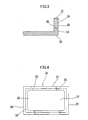
- FIGS. 3 and 5 are cross-sectional views of the tail cylinder taken along lines A-A and B-B of FIG.2, respectively.
- FIG. 4 is an end view of the end annular flange of the tail cylinder.
- a plurality of, for example, ten combustors 10 are circumferentially disposed around a central axis of a turbine rotor in an adjacent relationship to each other.
- each of the combustors 10 comprises a cylindrical structure including a liner 12 with a combustion nozzle (not shown) attached at one end of the combustor 10 and a tail cylinder 14 connected to the liner 12.
- a combustion nozzle not shown
- tail cylinder 14 connected to the liner 12.
- the tail cylinder 14 includes a front portion 16 disposed proximally to the rotational axis of the turbine rotor (not shown), a back portion 18 disposed distally from the rotational axis of the turbine rotor, and two side portions 20 disposed to abut a side portion of an adjacent tail cylinder (not shown) disposed around the rotational axis of the turbine rotor, respectively.
- the tail cylinder 14 is a flow passage for combustion gas disposed longitudinally thereof toward the discharge opening 22, at the outer circumference of which opening an end annular flange 24 is provided to connect the tail cylinder 14 to a turbine casing (not shown).
- the end annular flange 24 has an abutment surface 26 extending radially outwardly from the discharge opening 22 for connecting the flange 24 to the turbine casing.
- the discharge opening 22 is generally rectangular in shape, with the front portion 16 and the back portion 18 arranged as the long sides thereof, and with the side portions 20 arranged as the short sides thereof.
- the end annular flange 24 includes an outer portion 32 formed of a metal material having a coefficient of linear expansion greater than that of the metal material forming an inner portion 30 of the end annular flange. More particularly, as shown in FIG. 4, the end annular flange 24 includes a first annular portion 34 formed of a first metal material forming a circumferential portion of the discharge opening 22, and a second annular portion 36 formed of a second metal material having a coefficient of linear expansion greater than that of the first metal material, the second annular portion forming the circumferential portion of the first annular portion 34.
- the first and second annular portions 34, 36 are joined to each other by welding with a flux having a coefficient of linear expansion between that of the first metal material and that of the second metal material.
- the joining surface 38 between the first annular portion 34 and the second annular portion 36 is located in a parallel relationship with respect to the discharge opening 22.
- the first metal is hastelloy-X which has a coefficient of linear expansion of 1.5 E-5 (1/°C) (at 400 °C)
- the second metal is either A-286 or SUS stainless steel both of which has a coefficient of linear expansion of 1.8 E-5 (1/°C) (at 400 °C).
- A-286 is a more preferable material than SUS stainless steel due to its strength.
- the coefficient of linear expansion of the second metal material is 10% greater than the coefficient of the linear expansion of the first metal material, thereby eliminating the possibility of creating crackings due to the thermal fatigue.
- combustion gas is injected into the inner space of the liner 12 of the combustor 10 via one or more combustion nozzles (not shown), toward the discharge opening 22 of the tail cylinder 14. Then, the combustion gas is mixed with the air in the inner space of the combustor 10, and this mixture, i.e the working fluid, is supplied to the turbine rotor (not shown) through the discharge opening 22.
- the inner surface of the tail cylinder 14 is exposed to the combustion gas having a maximum temperature of 1500 °C, while the outer surface of the tail cylinder 14 is exposed to the outer environmental ambient air, resulting in a temperature gradient of several hundreds of degrees in the direction of the thickness of the wall of the tail cylinder 14.
- the difference between the thermal expansion of the higher temperature portion of the first metal and that of the lower temperature portion of the second metal will become less due to the larger amount of expansion of the lower temperature portion (so-called bimetal effect) during normal operation, than would be in the case of the higher and lower temperature portions of the same materials, resulting in reduced amount of the bending deformation, thereby reducing the thermal stress due to the deformation, especially at the corner portions thereof, so as to eliminate the possibility of creating crackings due to the thermal fatigue to provide the combustor 10 with a prolonged service life.
- FIG. 5 is a cross-sectional view of the second preferred embodiment of the tail cylinder of the combustor in accordance with the present invention, illustrated in the same manner as in FIG. 3.
- the end annular flange 24 of this embodiment has a lower height h than that of the previous embodiment to reduce the thermal stress.
- the height h can be selected depending upon the high temperature, the low temperature, and the characteristic of the metal material being used.
- the temperature of the inner surface of the tail cylinder i.e., higher temperature portion
- the temperature of the outer surface of the tail cylinder i.e., lower temperature portion
- the temperature difference between the two portions can be reduced, resulting in a reduced amount of bending deformation, thereby reducing the thermal stress due to the deformation, especially at the corner portions of the discharge opening of the end annular flange 24.
- the reduction of the efficiency of the gas turbine system which is caused by lowering the temperature of the higher temperature portion, can be prevented to a greater extent than in the case of the prior art wherein the temperature of the higher temperature portion is only lowered.
- FIG. 6 is a general overview of a third preferred embodiment of the hollow structure with a plurality of flanges in accordance with the present invention.
- a hollow structure i.e. an exhaust duct 50
- Each of the plurality of the annular flanges 52 is formed from a first metal material at a higher temperature portion of the exhaust duct 50, and a second metal material at a lower temperature portion of the exhaust duct 50, as in the first embodiment.
- the hollow structure i.e. the exhaust duct 50
- the hollow structure i.e. the exhaust duct 50
- the hollow structure will be expanded outwardly, as shown by the dotted line, due to the wide range of a temperature gradient in the direction of the thickness of the wall of the duct 50, similar to the case of the combustor of the first embodiment.
- the second metal material forming the lower temperature portion of the annular flanges 52 has a coefficient of linear expansion greater than that of the first metal material forming the higher temperature portion of the annular flanges 52, the flanges 52 can be expanded outwardly more than in the case of flanges consisting of one metal material.
- end annular flanges 24 of this embodiment have a bimetal-like structure at respective entire peripheries, only one or more portion/portions thereof, such as the front portion; back portion, or side portions, can have such a structure.
- the metal material forming the inner portion 30 of the end annular flange 24 was hastelloy-X, which has been used conventionally for constructing the tail cylinder 14, but any other suitable materials can be utilized.
- the outer portion 32 of the end annular flange 24 from the metal material having a coefficient of linear expansion at least a certain amount greater than that of the metal material forming the inner portion 30 of the end annular flange 24, the amount of the bending deformation at the corners of the discharge opening of the end annular flange 24 can be reduced, thereby reducing the thermal stress due to the deformation thereat, resulting in a prolonged service life thereof.
- a hollow structure having at least one flange which can eliminate the possibility of creating crackings due to the thermal fatigue, and thereby having an improved durability, has been provided.
Landscapes
- Engineering & Computer Science (AREA)
- General Engineering & Computer Science (AREA)
- Mechanical Engineering (AREA)
- Turbine Rotor Nozzle Sealing (AREA)
- Flanged Joints, Insulating Joints, And Other Joints (AREA)
- Heat-Exchange Devices With Radiators And Conduit Assemblies (AREA)
- Rod-Shaped Construction Members (AREA)
Abstract
Description
Claims (6)
- A hollow structure with an flange wherein at least one annular flange is fixedly attached around the hollow structure which has a temperature gradient in the direction of the thickness of the wall thereof comprising:said at least one annular flange including an outer portion formed of a metal material having a coefficient of linear expansion greater than that of the metal material forming another portion of said at least one annular flange.
- A hollow structure with an flange according to claim 1, wherein said hollow structure is one of a plurality of gas turbine combustors disposed circumferentially around a central axis of a turbine rotor in an adjacent relationship each other including a generally tubular-shaped tail cylinder for providing a flow path of combustion gas flowing longitudinally toward the discharge opening thereof, said tail cylinder having an end annular flange at the outer circumference of the discharge opening thereof for connecting to a turbine casing, wherein the end annular flange comprising said at least one flange;
wherein said end annular flange including an outer portion formed of a metal material having a coefficient of linear expansion greater than that of the metal material forming another portion of said end annular flange. - A hollow structure with an flange according to claim 1 or 2, wherein said end annular flange including a first annular portion formed of a first metal material forming a circumferential portion of the discharge opening, and a second annular portion formed of a second metal material having a coefficient of linear expansion greater than that of the first metal material; wherein said first and second annular portions are joined each other by welding with a flux having a coefficient of linear expansion between that of the first metal material and that of the second metal material.
- A hollow structure with an flange according to claim 3, wherein the coefficient of linear expansion of the second metal material is 10% greater than the coefficient of linear expansion of the first metal material.
- A hollow structure with an flange according to any one of claims 1 to 4,
wherein the metal material forming the inner portion of said flange is hastelloy-X, and the metal material forming the outer portion of said flange is A-286. - A hollow structure with an flange according to any one of claims 1 to 4, wherein the metal material forming the inner portion of said flange is hastelloy-X, and the metal material forming the outer portion of said flange is SUS stainless steel.
Applications Claiming Priority (3)
| Application Number | Priority Date | Filing Date | Title |
|---|---|---|---|
| JP2001198916 | 2001-06-29 | ||
| JP2001198916A JP4008212B2 (en) | 2001-06-29 | 2001-06-29 | Hollow structure with flange |
| PCT/JP2002/006641 WO2003002914A1 (en) | 2001-06-29 | 2002-07-01 | Flanged hollow structure |
Publications (3)
| Publication Number | Publication Date |
|---|---|
| EP1400755A1 true EP1400755A1 (en) | 2004-03-24 |
| EP1400755A4 EP1400755A4 (en) | 2007-05-09 |
| EP1400755B1 EP1400755B1 (en) | 2011-01-19 |
Family
ID=19036273
Family Applications (1)
| Application Number | Title | Priority Date | Filing Date |
|---|---|---|---|
| EP02738898A Expired - Lifetime EP1400755B1 (en) | 2001-06-29 | 2002-07-01 | Flanged hollow structure |
Country Status (7)
| Country | Link |
|---|---|
| US (1) | US6662568B2 (en) |
| EP (1) | EP1400755B1 (en) |
| JP (1) | JP4008212B2 (en) |
| CN (1) | CN1220845C (en) |
| CA (1) | CA2421802C (en) |
| DE (1) | DE60238984D1 (en) |
| WO (1) | WO2003002914A1 (en) |
Families Citing this family (31)
| Publication number | Priority date | Publication date | Assignee | Title |
|---|---|---|---|---|
| US7178341B2 (en) * | 2004-06-17 | 2007-02-20 | Siemens Power Generation, Inc. | Multi-zone tubing assembly for a transition piece of a gas turbine |
| US8015818B2 (en) * | 2005-02-22 | 2011-09-13 | Siemens Energy, Inc. | Cooled transition duct for a gas turbine engine |
| JP4476152B2 (en) * | 2005-04-01 | 2010-06-09 | 三菱重工業株式会社 | Gas turbine combustor |
| US7827801B2 (en) * | 2006-02-09 | 2010-11-09 | Siemens Energy, Inc. | Gas turbine engine transitions comprising closed cooled transition cooling channels |
| US8141370B2 (en) * | 2006-08-08 | 2012-03-27 | General Electric Company | Methods and apparatus for radially compliant component mounting |
| FR2942515B1 (en) * | 2009-02-24 | 2015-07-03 | Saint Gobain Ct Recherches | ASSEMBLY DEVICE. |
| US9234431B2 (en) * | 2010-07-20 | 2016-01-12 | Siemens Energy, Inc. | Seal assembly for controlling fluid flow |
| US8721278B2 (en) | 2010-08-02 | 2014-05-13 | Siemens Energy, Inc. | Exhaust manifold flange connection |
| EP2971611B1 (en) * | 2013-03-14 | 2019-10-02 | United Technologies Corporation | Turbine engine with multi-layered case flange |
| WO2016080957A1 (en) * | 2014-11-18 | 2016-05-26 | Siemens Aktiengesellschaft | Transition duct exit frame with insert |
| US10392950B2 (en) * | 2015-05-07 | 2019-08-27 | General Electric Company | Turbine band anti-chording flanges |
| US11149646B2 (en) * | 2015-09-02 | 2021-10-19 | General Electric Company | Piston ring assembly for a turbine engine |
| US10605459B2 (en) | 2016-03-25 | 2020-03-31 | General Electric Company | Integrated combustor nozzle for a segmented annular combustion system |
| US10830442B2 (en) | 2016-03-25 | 2020-11-10 | General Electric Company | Segmented annular combustion system with dual fuel capability |
| US10584876B2 (en) | 2016-03-25 | 2020-03-10 | General Electric Company | Micro-channel cooling of integrated combustor nozzle of a segmented annular combustion system |
| US11002190B2 (en) | 2016-03-25 | 2021-05-11 | General Electric Company | Segmented annular combustion system |
| US10641491B2 (en) | 2016-03-25 | 2020-05-05 | General Electric Company | Cooling of integrated combustor nozzle of segmented annular combustion system |
| US11428413B2 (en) | 2016-03-25 | 2022-08-30 | General Electric Company | Fuel injection module for segmented annular combustion system |
| US10520194B2 (en) | 2016-03-25 | 2019-12-31 | General Electric Company | Radially stacked fuel injection module for a segmented annular combustion system |
| US10563869B2 (en) | 2016-03-25 | 2020-02-18 | General Electric Company | Operation and turndown of a segmented annular combustion system |
| US10584880B2 (en) | 2016-03-25 | 2020-03-10 | General Electric Company | Mounting of integrated combustor nozzles in a segmented annular combustion system |
| US11156362B2 (en) | 2016-11-28 | 2021-10-26 | General Electric Company | Combustor with axially staged fuel injection |
| US10690350B2 (en) | 2016-11-28 | 2020-06-23 | General Electric Company | Combustor with axially staged fuel injection |
| US11994292B2 (en) | 2020-08-31 | 2024-05-28 | General Electric Company | Impingement cooling apparatus for turbomachine |
| US11994293B2 (en) | 2020-08-31 | 2024-05-28 | General Electric Company | Impingement cooling apparatus support structure and method of manufacture |
| US11460191B2 (en) | 2020-08-31 | 2022-10-04 | General Electric Company | Cooling insert for a turbomachine |
| US11371702B2 (en) | 2020-08-31 | 2022-06-28 | General Electric Company | Impingement panel for a turbomachine |
| US11614233B2 (en) | 2020-08-31 | 2023-03-28 | General Electric Company | Impingement panel support structure and method of manufacture |
| US11255545B1 (en) | 2020-10-26 | 2022-02-22 | General Electric Company | Integrated combustion nozzle having a unified head end |
| US11767766B1 (en) | 2022-07-29 | 2023-09-26 | General Electric Company | Turbomachine airfoil having impingement cooling passages |
| CN120969598B (en) * | 2025-10-20 | 2026-01-30 | 航天晨光(福建)管业科技有限公司 | Quick installation device of special compound RTP pipeline of heavy-calibre |
Family Cites Families (13)
| Publication number | Priority date | Publication date | Assignee | Title |
|---|---|---|---|---|
| GB1362281A (en) * | 1970-08-17 | 1974-08-07 | Lausch H | Reinforced glass tubes |
| JPH063267Y2 (en) * | 1987-03-26 | 1994-01-26 | 日本碍子株式会社 | Bonding structure of ceramic cylinders |
| JPH03141847A (en) * | 1989-10-27 | 1991-06-17 | Nissan Motor Co Ltd | Cylinder block for internal combustion engine |
| JPH063267A (en) | 1992-06-20 | 1994-01-11 | Horiba Ltd | Method and device for detecting organic compound |
| JPH05215584A (en) * | 1991-11-20 | 1993-08-24 | Tokico Ltd | Vibration type measuring device |
| JPH06241363A (en) * | 1993-02-10 | 1994-08-30 | Toshiomi Hayashi | Flange joint assembly and its connecting method |
| GB2300909B (en) * | 1995-05-18 | 1998-09-30 | Europ Gas Turbines Ltd | A gas turbine gas duct arrangement |
| US5906093A (en) * | 1997-02-21 | 1999-05-25 | Siemens Westinghouse Power Corporation | Gas turbine combustor transition |
| US6018950A (en) * | 1997-06-13 | 2000-02-01 | Siemens Westinghouse Power Corporation | Combustion turbine modular cooling panel |
| JP4031590B2 (en) * | 1999-03-08 | 2008-01-09 | 三菱重工業株式会社 | Combustor transition structure and gas turbine using the structure |
| JP2001050448A (en) * | 1999-08-02 | 2001-02-23 | Ishikawajima Harima Heavy Ind Co Ltd | Joint structure of tubular member |
| US6397603B1 (en) * | 2000-05-05 | 2002-06-04 | The United States Of America As Represented By The Secretary Of The Air Force | Conbustor having a ceramic matrix composite liner |
| JP2002243154A (en) * | 2001-02-16 | 2002-08-28 | Mitsubishi Heavy Ind Ltd | Gas turbine combustor and tail cylinder outlet structure thereof |
-
2001
- 2001-06-29 JP JP2001198916A patent/JP4008212B2/en not_active Expired - Fee Related
-
2002
- 2002-07-01 CA CA002421802A patent/CA2421802C/en not_active Expired - Fee Related
- 2002-07-01 CN CNB028023994A patent/CN1220845C/en not_active Expired - Fee Related
- 2002-07-01 WO PCT/JP2002/006641 patent/WO2003002914A1/en not_active Ceased
- 2002-07-01 DE DE60238984T patent/DE60238984D1/en not_active Expired - Lifetime
- 2002-07-01 EP EP02738898A patent/EP1400755B1/en not_active Expired - Lifetime
-
2003
- 2003-03-05 US US10/378,602 patent/US6662568B2/en not_active Expired - Lifetime
Also Published As
| Publication number | Publication date |
|---|---|
| US6662568B2 (en) | 2003-12-16 |
| CN1464960A (en) | 2003-12-31 |
| DE60238984D1 (en) | 2011-03-03 |
| EP1400755B1 (en) | 2011-01-19 |
| JP4008212B2 (en) | 2007-11-14 |
| JP2003014237A (en) | 2003-01-15 |
| CA2421802A1 (en) | 2003-03-07 |
| WO2003002914A1 (en) | 2003-01-09 |
| CA2421802C (en) | 2007-08-21 |
| CN1220845C (en) | 2005-09-28 |
| EP1400755A4 (en) | 2007-05-09 |
| HK1063343A1 (en) | 2004-12-24 |
| US20030140633A1 (en) | 2003-07-31 |
Similar Documents
| Publication | Publication Date | Title |
|---|---|---|
| US6662568B2 (en) | Hollow structure with flange | |
| US4485630A (en) | Combustor liner | |
| EP1856376B1 (en) | Cooled transition duct for a gas turbine engine | |
| US8469661B2 (en) | Fabricated gas turbine vane ring | |
| EP0178242B1 (en) | Cooling scheme for combustor vane interface | |
| US10731494B2 (en) | Overhanging seal assembly for a gas turbine | |
| US5248240A (en) | Turbine stator vane assembly | |
| JP4856306B2 (en) | Stationary components of gas turbine engine flow passages. | |
| EP1548231B1 (en) | Fairing for a turbine frame strut | |
| US6199371B1 (en) | Thermally compliant liner | |
| US4805397A (en) | Combustion chamber structure for a turbojet engine | |
| EP0150656A1 (en) | Coated high temperature combustor liner | |
| EP2211105A2 (en) | Turbulated combustor aft-end liner assembly and related cooling method | |
| US10718450B2 (en) | Flange joint assembly for use in a gas turbine engine | |
| JP2003201807A (en) | Suppression seal with thermal compliance | |
| JP2007513281A (en) | Peristaltic joint between combustor wall and nozzle platform | |
| EP3805526B1 (en) | Seal assembly for chute gap leakage reduction in a gas turbine | |
| CN107923259A (en) | The device of the manifold of the shell for the turbine for passing through air jet cooling turbine engines for attachment | |
| JP4266754B2 (en) | Assembly cowl for gas turbine engine dual annular combustor and its fabrication method. | |
| US4262487A (en) | Double wall combustion chamber for a combustion turbine | |
| HK1063343B (en) | Flanged hollow structure | |
| JPS6055723B2 (en) | Combustor for stationary gas turbine | |
| EP3221562B1 (en) | Transition duct exit frame with insert | |
| JPH0953462A (en) | Gas turbine containment ring | |
| JPH0571736A (en) | Gas turbine combustion apparatus |
Legal Events
| Date | Code | Title | Description |
|---|---|---|---|
| PUAI | Public reference made under article 153(3) epc to a published international application that has entered the european phase |
Free format text: ORIGINAL CODE: 0009012 |
|
| 17P | Request for examination filed |
Effective date: 20030311 |
|
| AK | Designated contracting states |
Kind code of ref document: A1 Designated state(s): AT BE BG CH CY CZ DE DK EE ES FI FR GB GR IE IT LI LU MC NL PT SE SK TR |
|
| REG | Reference to a national code |
Ref country code: HK Ref legal event code: DE Ref document number: 1063343 Country of ref document: HK |
|
| A4 | Supplementary search report drawn up and despatched |
Effective date: 20070405 |
|
| RIC1 | Information provided on ipc code assigned before grant |
Ipc: F23R 3/42 20060101AFI20030113BHEP Ipc: F01D 9/02 20060101ALI20070330BHEP Ipc: F16L 23/00 20060101ALI20070330BHEP |
|
| 17Q | First examination report despatched |
Effective date: 20070808 |
|
| GRAP | Despatch of communication of intention to grant a patent |
Free format text: ORIGINAL CODE: EPIDOSNIGR1 |
|
| GRAS | Grant fee paid |
Free format text: ORIGINAL CODE: EPIDOSNIGR3 |
|
| GRAA | (expected) grant |
Free format text: ORIGINAL CODE: 0009210 |
|
| AK | Designated contracting states |
Kind code of ref document: B1 Designated state(s): CH DE FR GB IT LI |
|
| REG | Reference to a national code |
Ref country code: GB Ref legal event code: FG4D |
|
| REG | Reference to a national code |
Ref country code: CH Ref legal event code: NV Representative=s name: E. BLUM & CO. AG PATENT- UND MARKENANWAELTE VSP Ref country code: CH Ref legal event code: EP |
|
| REF | Corresponds to: |
Ref document number: 60238984 Country of ref document: DE Date of ref document: 20110303 Kind code of ref document: P |
|
| REG | Reference to a national code |
Ref country code: DE Ref legal event code: R096 Ref document number: 60238984 Country of ref document: DE Effective date: 20110303 |
|
| REG | Reference to a national code |
Ref country code: HK Ref legal event code: GR Ref document number: 1063343 Country of ref document: HK |
|
| PGFP | Annual fee paid to national office [announced via postgrant information from national office to epo] |
Ref country code: CH Payment date: 20110712 Year of fee payment: 10 |
|
| PLBE | No opposition filed within time limit |
Free format text: ORIGINAL CODE: 0009261 |
|
| STAA | Information on the status of an ep patent application or granted ep patent |
Free format text: STATUS: NO OPPOSITION FILED WITHIN TIME LIMIT |
|
| 26N | No opposition filed |
Effective date: 20111020 |
|
| REG | Reference to a national code |
Ref country code: DE Ref legal event code: R097 Ref document number: 60238984 Country of ref document: DE Effective date: 20111020 |
|
| PGFP | Annual fee paid to national office [announced via postgrant information from national office to epo] |
Ref country code: GB Payment date: 20120627 Year of fee payment: 11 |
|
| PGFP | Annual fee paid to national office [announced via postgrant information from national office to epo] |
Ref country code: IT Payment date: 20120712 Year of fee payment: 11 Ref country code: FR Payment date: 20120719 Year of fee payment: 11 Ref country code: DE Payment date: 20120627 Year of fee payment: 11 |
|
| REG | Reference to a national code |
Ref country code: CH Ref legal event code: PL |
|
| GBPC | Gb: european patent ceased through non-payment of renewal fee |
Effective date: 20130701 |
|
| REG | Reference to a national code |
Ref country code: FR Ref legal event code: ST Effective date: 20140331 |
|
| PG25 | Lapsed in a contracting state [announced via postgrant information from national office to epo] |
Ref country code: DE Free format text: LAPSE BECAUSE OF NON-PAYMENT OF DUE FEES Effective date: 20140201 Ref country code: CH Free format text: LAPSE BECAUSE OF NON-PAYMENT OF DUE FEES Effective date: 20130731 Ref country code: LI Free format text: LAPSE BECAUSE OF NON-PAYMENT OF DUE FEES Effective date: 20130731 Ref country code: GB Free format text: LAPSE BECAUSE OF NON-PAYMENT OF DUE FEES Effective date: 20130701 |
|
| REG | Reference to a national code |
Ref country code: DE Ref legal event code: R119 Ref document number: 60238984 Country of ref document: DE Effective date: 20140201 |
|
| PG25 | Lapsed in a contracting state [announced via postgrant information from national office to epo] |
Ref country code: IT Free format text: LAPSE BECAUSE OF NON-PAYMENT OF DUE FEES Effective date: 20130701 Ref country code: FR Free format text: LAPSE BECAUSE OF NON-PAYMENT OF DUE FEES Effective date: 20130731 |