EP1400718A1 - Clutch engagement detector and uniaxial combined plant having the detector - Google Patents
Clutch engagement detector and uniaxial combined plant having the detector Download PDFInfo
- Publication number
- EP1400718A1 EP1400718A1 EP02741333A EP02741333A EP1400718A1 EP 1400718 A1 EP1400718 A1 EP 1400718A1 EP 02741333 A EP02741333 A EP 02741333A EP 02741333 A EP02741333 A EP 02741333A EP 1400718 A1 EP1400718 A1 EP 1400718A1
- Authority
- EP
- European Patent Office
- Prior art keywords
- clutch
- rotating machine
- rotational speed
- engagement
- steam turbine
- Prior art date
- Legal status (The legal status is an assumption and is not a legal conclusion. Google has not performed a legal analysis and makes no representation as to the accuracy of the status listed.)
- Granted
Links
Images



Classifications
-
- F—MECHANICAL ENGINEERING; LIGHTING; HEATING; WEAPONS; BLASTING
- F01—MACHINES OR ENGINES IN GENERAL; ENGINE PLANTS IN GENERAL; STEAM ENGINES
- F01K—STEAM ENGINE PLANTS; STEAM ACCUMULATORS; ENGINE PLANTS NOT OTHERWISE PROVIDED FOR; ENGINES USING SPECIAL WORKING FLUIDS OR CYCLES
- F01K23/00—Plants characterised by more than one engine delivering power external to the plant, the engines being driven by different fluids
- F01K23/12—Plants characterised by more than one engine delivering power external to the plant, the engines being driven by different fluids the engines being mechanically coupled
- F01K23/16—Plants characterised by more than one engine delivering power external to the plant, the engines being driven by different fluids the engines being mechanically coupled all the engines being turbines
Definitions
- This invention relates to a clutch engagement detecting apparatus for detecting the state of engagement of a clutch, and a single-shaft combined plant having it.
- a single-shaft combined plant having a gas turbine and a steam turbine connected by a single shaft, is a plant with a high efficiency, involving minimal emission of hazardous substances (NOX, etc.), and flexibly accommodating diurnal changes in electric power consumption. Recently, demand has grown for a further decrease in the construction cost for this single-shaft combined plant.
- a conventional single-shaft combined plant involved the following factors behind the cost increase:
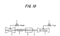
- FIG. 10 To reduce the construction cost, a proposal has now been made for a single-shaft combined plant to which a clutch, as shown in FIG. 10, has been applied.
- a gas turbine 1 and a steam turbine 2 are connected by a single shaft 3, and a generator 4 is also connected to the shaft 3.
- a clutch 5 is interposed between the gas turbine 1 (generator 4) and the steam turbine 2, and this clutch 5 enables the gas turbine 1 and the steam turbine 2 to be connected and disconnected.
- Fuel is supplied to the gas turbine 1 via a fuel control valve 7, while steam from an exhaust gas boiler or the like is supplied to the steam turbine 6 via a steam governing valve 6.
- the clutch 5 uses a helical spline engagement structure (the same as a clutch 15 shown in FIG. 6; details will be offered later).
- a helical spline engagement structure (the same as a clutch 15 shown in FIG. 6; details will be offered later).
- the capacity of the thyristor necessary for starting can be decreased (the capacity may be decreased by an amount corresponding to the weight of the steam turbine 2).
- the steam turbine 2 rotates at a low speed, requiring no cooling steam.
- the capacity of the auxiliary boiler can be decreased.
- This position sensor is constituted such that a high frequency current is flowed through a coil at the front end of the sensor to generate eddy currents in an object of detection (the aforementioned sliding component), and changes in the impedance of the coil in response to changes in the eddy currents are measured to detect the position of the object of detection.
- the present invention has been made in view of the above circumstances. Its problem is to provide a clutch engagement detecting apparatus, which can accurately detect the state of engagement of a clutch using a helical spline engagement structure, and a single-shaft combined plant equipped with the clutch engagement detecting apparatus.
- a clutch engagement detecting apparatus of a first invention for solving the above problem is a clutch engagement detecting apparatus for detecting the state of engagement of a clutch using a helical spline engagement structure interposed between a first rotating machine and a second rotating machine, characterized by having a clutch engagement determination logic which determines that the clutch is engaged if the difference between the detected value of the rotational speed of the first rotating machine and the detected value of the rotational speed of the second rotating machine is not more than the detection error of rotation detecting meters for detecting the rotational speeds of the first rotating machine and the second rotating machine at a time when a predetermined time has passed during engagement of the clutch for connecting the second rotating machine to the first rotating machine.
- the engagement of the clutch can be detected more reliably by the clutch engagement determination logic.
- a clutch engagement detecting apparatus of a second invention is the clutch engagement detecting apparatus of the first invention, characterized by having a clutch abnormality determination logic which determines that the clutch is abnormal if the detected value of the rotational speed of the second rotating machine exceeds the detected value of the rotational speed of the first rotating machine by a predetermined rotational speed or more, or if the detected value of the rotational speed of the second rotating machine falls short of the detected value of the rotational speed of the first rotating machine by a predetermined rotational speed or more after the clutch engagement determination logic has determined that the clutch is engaged.
- an abnormality of the clutch can be detected reliably by the clutch abnormality determination logic.
- a clutch engagement detecting apparatus of a third invention is a clutch engagement detecting apparatus for detecting the state of engagement of a clutch using a helical spline engagement structure interposed between a first rotating machine and a second rotating machine, characterized by including pulse generation means for outputting pulse signals at constant rotation angles of the first rotating machine and the second rotating machine, and a first counter and a second counter, and characterized in that when the clutch is engaged to connect the second rotating machine to the first rotating machine, the first counter counts the number of pulses generated from the pulse generation means in response to the rotations of the second rotating machine for a constant number of pulses generated from the pulse generation means in response to the rotations of the first rotating machine, whereas the second counter does addition or subtraction according to the counted value of the first counter, and a logic is further provided for determining the state of engagement of the clutch based on the counted value of the second counter corresponding to the relative rotation angle between the first rotating machine and the second rotating machine.
- the engaged state of the clutch can be determined reliably. Furthermore, the engaged state of the clutch can be grasped more concretely. In detail, even when the first rotating machine and the second rotating machine rotate at the same rotational speed, this does not necessarily mean that the clutch is completely engaged. According to the third invention, by contrast, it is possible to determine whether the clutch is completely engaged, or bonded halfway through engagement.
- a single-shaft combined plant of a fourth invention is a single-shaft combined plant comprising a gas turbine and a steam turbine connected together by a single shaft, and a clutch using a helical spline engagement structure interposed between the gas turbine and the steam turbine, whereby the gas turbine and the steam turbine can be connected to or disconnected from each other, characterized by including the clutch engagement detecting apparatus of the first, second or third invention, and characterized in that the first rotating machine is a gas turbine and the second rotating machine is a steam turbine.
- a gas turbine 11 and a steam turbine 12 are connected by a single shaft 13, and a generator 14 is also connected to the shaft 13.
- a clutch 15 is interposed between the gas turbine 11 (generator 14) and the steam turbine 12, and this clutch 15 enables the gas turbine 11 and the steam turbine 12 to be connected and disconnected, thereby decreasing the capacity of a thyristor and an auxiliary boiler.
- Fuel is supplied to the gas turbine 11 via a fuel control valve 17, while steam from an exhaust gas boiler or the like is supplied to the steam turbine 12 via a steam governing valve 16. So-called SSS Clutch (trade name) can be applied as the clutch 15.
- the clutch 15 is of a publicly known type using a helical spline engagement structure, and has the following characteristics:
- the concrete structure of the clutch 15 is as shown in FIGS. 6, 7(a) and 7(b).
- the clutch 15 has a drive component and a driven component (input component and output component) 31 and 32 provided on both sides in an axial direction (right-and-left direction in the drawing), and a sliding component 33 provided between the drive component 31 and the driven component 32.
- the sliding component 33 in FIG. 6 is hatched.
- the drive component 31 is connected to a rotating shaft 3 of the steam turbine 12, and rotates together with the steam turbine 12.
- the driven component 32 is connected to the rotating shaft 3 of the gas turbine 11 (generator 14), and rotates together with the gas turbine 11 (generator 14).
- the sliding component 33 rotates along with the drive component 31 before engagement of the clutch, and rotates along with the drive component/driven component 31, 32 after engagement of the clutch.
- the sliding component 33 comprises a body portion 34, and a sliding portion 35 slidably engaged with the body portion 34 at a helical spline engagement portion 36.
- the sliding portion 35 moves axially while rotating because of the helical spline engagement portion 36.
- the body portion 34 is slidably engaged with the drive component 31 at a helical spline engagement portion 37, and moves axially while rotating because of the helical spline engagement portion 37.
- the body portion 34 of the sliding component 33 moves leftward in the drawing, its main gear 38 engages with a main gear 39 of the driven component 32.
- the upper half shows the state before engagement, while the lower half shows the state of complete engagement.
- a primary pawl 40 urged by a spring 42 is provided in the driven component 32.
- a low speed region up to about 500 rpm
- the primary pawl 40 attached to the driven component 32 is engaged (ratcheted) with an engagement portion (ratchet portion) 43 of the outer periphery of the sliding portion 35 of the sliding component 33, whereupon the sliding portion 35 rotates together with the driven component 32.
- the primary pawl 40 fails to function under a centrifugal force, but a secondary pawl 41 begins working.
- the rotational speed of the steam turbine 12 namely, the rotational speed of the sliding component 33 rotating together with the steam turbine 12 (drive component 31)
- the secondary pawl 41 attached to the sliding portion 35 of the sliding component 33 is engaged (ratcheted) with an engagement portion (ratchet portion) 44 of the inner periphery of the driven component 32, whereupon the sliding portion 35 rotates together with the driven component 32.
- the helical spline engagement portion 37 functions to move the sliding component 33 rightward in the drawing, thereby releasing the main gears 38 and 39 from engagement.
- the helical spline engagement portion 36 functions to move the sliding portion 35 rightward in the drawing, thereby releasing the auxiliary gears 45 and 46 from engagement.
- the primary pawl 40 or the secondary pawl 41 is placed in a wait state, and completely disengaged.
- the single-shaft combined plant of the present embodiment is equipped with a clutch engagement detecting apparatus 51 as shown in FIG. 1.
- the clutch engagement detecting apparatus 51 has rotation detecting meters 52, 53 and a logic device 53.
- the rotation detecting meters 52, 53 are installed for detecting the rotational speeds of the gas turbine 11 and the steam turbine 12 without contacting them. They are general meters which output pulse signals for each constant rotation angle of the gas turbine 11 or the steam turbine 12 (for example, 60 pulse signals for each rotation), and compute these pulse signals to obtain the rotational speeds. Suitable meters, such as eddy current electromagnetic pick-ups, can be used as the rotation detecting meters 52, 53. In the present Embodiment 1, the rotation detecting meter is not necessarily limited to that which outputs pulse signals, but a rotation detecting meter of other type can be employed.
- Rotational speed detection signals from the rotation detecting meters 52, 53 are inputted into the logic device 54.
- the logic device 54 includes a clutch engagement determination logic as shown in FIG. 2, and a clutch abnormality determination logic as shown in FIG. 3.
- the clutch engagement determination logic works in the following manner: Load is entered into the steam turbine 12 (a steam turbine load entry signal is outputted) (S1). Then, a predetermined time, set by ODN (ON DELAY TIMER: one which outputs an inputted ON signal with a predetermined time delay), elapses (S2). If the difference between the detected value of the rotational speed of the gas turbine 11 by the rotation detecting meter 52 and the detected value of the rotational speed of the steam turbine 12 by the rotation detecting meter 53 is not more than the detection error of the rotation detecting meters 52, 53 (S3) by the time when the predetermined time has passed (S2) after S1, AND conditions are fulfilled (S4). Thus, it is determined that the clutch 15 has been engaged, whereupon a clutch engagement detection signal is outputted (S5).
- ODN ON DELAY TIMER: one which outputs an inputted ON signal with a predetermined time delay
- the rotational speed of the steam turbine 2 increases, and the difference in rotational speed between the steam turbine 12 and the gas turbine 11 decreases. Then, steam enough to impose load on the steam turbine 12 is entered into the steam turbine 12. Then, the steam turbine 12 is run for a while (until a predetermined time elapses). If, by this time, the difference in rotational speed between the steam turbine 12 and the gas turbine 11 is not more than the detection error of the rotation detecting meters 52, 53, it is determined that the clutch 15 is in engagement.
- the steam turbine start logic as shown in FIG. 3 is constructed.
- the contents of the steam turbine start logic are as follows:
- a clutch abnormality signal (S44) of the clutch abnormality determination logic is also incorporated into such a turbine protection interlock logic (relay circuit). By so doing, when the clutch abnormality signal (S44) is outputted, the tripping electromagnetic valve 18 is opened, enabling the steam turbine 12 and the gas turbine 11 to be stopped.
- the clutch abnormality detection logic is multiplexed (triplexed). According to this logic, if "the condition that the detected value of the rotational speed of the steam turbine 12 surpasses the detected value of the rotational speed of the gas turbine 11 by not less than the predetermined rotational speed ⁇ " or "the condition that after clutch engagement is detected by the clutch engagement determination logic, the detected value of the rotational speed of the steam turbine 12 falls short of the detected value of the rotational speed of the gas turbine 11 by not less than the predetermined rotational speed ⁇ " is fulfilled in two of the three conditions (S55, S59), the clutch abnormality signal (S44) is outputted (S46 to S60).
- engagement of the clutch 15 can be detected more reliably by the clutch engagement determination logic shown in FIG. 2.
- clutch abnormality can be detected reliably by the clutch abnormality determination logic shown in FIG. 4.
- the clutch engagement determination logic and the clutch abnormality determination logic are essential to the single-shaft combined plant using the clutch 15.
- a single-shaft combined plant can be produced at a lower cost than before with the use of the clutch 15.
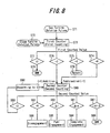
- a logic as shown in FIG. 8 may be provided in the logic device 54 of FIG. 1.
- the rotation detecting meters 52, 53 are used as pulse generation means. That is, rotation pulse signals outputted from the rotation detecting meters 52, 53 are utilized.
- the pulse generation means are not limited to these meters, but may be those which output pulse signals for each constant rotation angle of the gas turbine 11 (gas turbine rotation pulses), and which output pulse signals for each constant rotation angle of the steam turbine 12 (steam turbine rotation pulses). The gas turbine rotation pulses and the steam turbine rotation pulses are outputted for the same constant rotation angle.
- a first counter counts (first counting) the number of pulses outputted from the pulse generation means (rotation detecting meter 53) according to rotations of the steam turbine 12 (steam turbine rotation pulses) for each constant number of pulses outputted from the pulse generation means (rotation detecting meter 52) according to rotations of the gas turbine 11 (gas turbine rotation pulses) (S71, S71, S73). That is, the counted value is reset for the above constant number, and the steam turbine rotation pulses are counted newly from 1.
- the counting cycle for the steam turbine rotation pulses may involve any number of the gas turbine rotation pulses.
- the first counter is designed to count the number of the steam turbine rotation pulses outputted during a period between the time when one gas turbine rotation pulse is outputted and the time when the next gas turbine rotation pulse is outputted.
- the first counted value by the first counter comes to be 0 (S74), 1 (S75), 2 (S76), or greater than 2 (S77), according to the rotational speed of the steam turbine 12.
- the first counted value is 1 or 0, like the first counted value A.
- the first counted value is continuously 1, like the first counted value B.
- the first counted value is 2 or 1, like the first counted value C.
- the program goes to "Return” (S78). If the first counted value is greater than 2, "ANN (alarm)” is issued (S77). That is, if the first counted value is greater than 2, "ANN (alarm)” is issued on the assumption that the rotational speed of the steam turbine has become abnormally higher than the rotational speed of the gas turbine, because of, say, failure in the primary pawl 40 or the secondary pawl 41 (no ratcheting) (this case means that the rotational speed of the steam turbine has been detected to be not less than 150% of the rotational speed of the gas turbine; this is physically impossible and can be judged to come from failure in the logic or the measuring instrument).
- the second counter performs counting (second counting) (S80).
- second counting when the first counted value is 2, 1 is added (counted up), and when the first counted value is 0, 1 is subtracted (counted down).
- the second counted value by the second counter is as follows: In the case of “the first counted value A”, ⁇ changes into ⁇ - 1 because of a decrease like "second counted value A”. For “the first counted value B”, ⁇ remains unchanged like “the second counted value B”. In the case of "the first counted value C”, ⁇ changes into ⁇ + 1 like "the second counted value C”.
- the second counter has the function of being automatically reset to 0, if the second counted value of the second counter is not more than 0 (S89, S90). If the second counted value of the second counter is not less than ⁇ + ⁇ , it is determined that the control logic or the clutch has failed, issuing "ANN (alarm)" (S87, S88).
- the rotational speed of the steam turbine slightly surpasses the rotational speed of the gas turbine, and this state continues for a certain period of time (a time until the helical spline engagement portions are completely engaged).
- the state of the first counted value becoming 2 or becoming 2 or 1 continues.
- the second counted value increases to the predetermined value ⁇ or more until complete engagement is accomplished (until the rotational speed of the steam turbine and the rotational speed of the gas turbine become equal, making the first counted value continuously 1).
- the second counted value of the second counter is proportional to the relative rotation angle between the steam turbine shaft and the gas turbine shaft at the helical spline engagement portions 36, 37. Hence, by monitoring whether the second counted value has become larger than the predetermined value ⁇ , it can be determined whether the clutch 15 has completely engaged or not.
- the rotational speed of the steam turbine and the rotational speed of the gas turbine become equal at this time, making the first counted value continuously 1, so that the second counted value does not reach the predetermined value ⁇ .
- the rotational speed of the steam turbine is lower than the rotational speed of the gas turbine, the first counted value is 0 or 1, so that the second counted value is subtracted and decreased. If the second counted value is 0, therefore, it can be determined that the clutch 15 has disengaged.
- the respective values set in this logic may be changed, where necessary, according to the actual clutch characteristics, the pulse counting cycle (for what number of the gas turbine rotation pulses should the steam turbine rotation pulses be counted?) and so on.
- engagement of the clutch 15 or abnormality in the clutch 15 can be detected reliably, thus contributing to the realization of a single-shaft combined plant using the clutch 15.
- the engaged state of the clutch 15 can be grasped more concretely.
- the fact that the gas turbine 11 and the steam turbine 12 rotate at the same rotational speed does not necessarily mean that the clutch 15 is completely engaged.
- the present invention is effective for application to a single-shaft combined plant using the clutch 15, but is not necessarily limited thereto.
- the invention is also applicable to a case where the clutch 15 is interposed between rotating machines other than a gas turbine and a steam turbine.
- This invention relates to a clutch engagement detecting apparatus for detecting the state of engagement of a clutch, and a single-shaft combined plant having it.
- the invention is particularly useful for application to a single-shaft combined plant having a clutch using a helical spline engagement structure provided between a gas turbine and a steam turbine.
Landscapes
- Engineering & Computer Science (AREA)
- Chemical & Material Sciences (AREA)
- Combustion & Propulsion (AREA)
- Mechanical Engineering (AREA)
- General Engineering & Computer Science (AREA)
- Engine Equipment That Uses Special Cycles (AREA)
- Hydraulic Clutches, Magnetic Clutches, Fluid Clutches, And Fluid Joints (AREA)
Abstract
Description
Claims (4)
- A clutch engagement detecting apparatus for detecting a state of engagement of a clutch using a helical spline engagement structure interposed between a first rotating machine and a second rotating machine,
characterized by having
a clutch engagement determination logic which determines that the clutch is engaged if a difference between a detected value of a rotational speed of the first rotating machine and a detected value of a rotational speed of the second rotating machine is not more than a detection error of rotation detecting meters for detecting the rotational speeds of the first rotating machine and the second rotating machine at a time when a predetermined time has passed during engagement of the clutch for connecting the second rotating machine to the first rotating machine. - The clutch engagement detecting apparatus of claim 1, characterized by having
a clutch abnormality determination logic which determines that the clutch is abnormal if the detected value of the rotational speed of the second rotating machine exceeds the detected value of the rotational speed of the first rotating machine by a predetermined rotational speed or more, or if the detected value of the rotational speed of the second rotating machine falls short of the detected value of the rotational speed of the first rotating machine by a predetermined rotational speed or more after the clutch engagement determination logic has determined that the clutch is engaged. - A clutch engagement detecting apparatus for detecting a state of engagement of a clutch using a helical spline engagement structure interposed between a first rotating machine and a second rotating machine,
characterized by including
pulse generation means for outputting pulse signals at constant rotation angles of the first rotating machine and the second rotating machine, and
a first counter and a second counter, and
characterized in that
when the clutch is engaged to connect the second rotating machine to the first rotating machine, the first counter counts the number of pulses generated from the pulse generation means in response to rotations of the second rotating machine for a constant number of pulses generated from the pulse generation means in response to rotations of the first rotating machine, whereas the second counter does addition or subtraction according to a counted value of the first counter, and
a logic is further provided for determining the state of engagement of the clutch based on a counted value of the second counter corresponding to a relative rotation angle between the first rotating machine and the second rotating machine. - A single-shaft combined plant comprising a gas turbine and a steam turbine connected together by a single shaft, and a clutch using a helical spline engagement structure interposed between the gas turbine and the steam turbine, whereby the gas turbine and the steam turbine can be connected to or disconnected from each other,
characterized by including the clutch engagement detecting apparatus of claim 1, 2 or 3, and characterized in that the first rotating machine is a gas turbine and the second rotating machine is a steam turbine.
Applications Claiming Priority (3)
| Application Number | Priority Date | Filing Date | Title |
|---|---|---|---|
| JP2001196127 | 2001-06-28 | ||
| JP2001196127A JP2003013709A (en) | 2001-06-28 | 2001-06-28 | Clutch engagement detecting device and single-shaft combined plant having the same |
| PCT/JP2002/006409 WO2003002883A1 (en) | 2001-06-28 | 2002-06-26 | Clutch engagement detector and uniaxial combined plant having the detector |
Publications (3)
| Publication Number | Publication Date |
|---|---|
| EP1400718A1 true EP1400718A1 (en) | 2004-03-24 |
| EP1400718A4 EP1400718A4 (en) | 2006-10-11 |
| EP1400718B1 EP1400718B1 (en) | 2013-08-14 |
Family
ID=19033991
Family Applications (1)
| Application Number | Title | Priority Date | Filing Date |
|---|---|---|---|
| EP02741333.5A Expired - Lifetime EP1400718B1 (en) | 2001-06-28 | 2002-06-26 | Clutch engagement detector and uniaxial combined plant having the detector |
Country Status (6)
| Country | Link |
|---|---|
| US (1) | US6810669B2 (en) |
| EP (1) | EP1400718B1 (en) |
| JP (1) | JP2003013709A (en) |
| CN (1) | CN1256525C (en) |
| CA (1) | CA2426255C (en) |
| WO (1) | WO2003002883A1 (en) |
Cited By (1)
| Publication number | Priority date | Publication date | Assignee | Title |
|---|---|---|---|---|
| EP1591628A1 (en) * | 2004-04-30 | 2005-11-02 | Siemens Aktiengesellschaft | Combined power plant and cooling method therefor |
Families Citing this family (24)
| Publication number | Priority date | Publication date | Assignee | Title |
|---|---|---|---|---|
| JP3692340B2 (en) * | 2002-07-30 | 2005-09-07 | 三菱重工業株式会社 | COMBINED PLANT FUEL CONTROL METHOD AND CONTROL DEVICE FOR THE SAME |
| JP3930462B2 (en) * | 2003-08-01 | 2007-06-13 | 株式会社日立製作所 | Single-shaft combined cycle power generation facility and operation method thereof |
| JP4452053B2 (en) * | 2003-10-01 | 2010-04-21 | 三菱重工業株式会社 | Axis deviation measuring device |
| US7732363B2 (en) | 2005-12-20 | 2010-06-08 | Chevron U.S.A. Inc. | Regeneration of acidic catalysts |
| EP1911939A1 (en) * | 2006-10-09 | 2008-04-16 | Siemens Aktiengesellschaft | Coupling action control with coupling angle |
| GB0707376D0 (en) * | 2007-04-17 | 2007-05-23 | Penny & Giles Controls Ltd | Inductive sensors |
| JP5185677B2 (en) | 2008-03-31 | 2013-04-17 | 三菱重工業株式会社 | Axial displacement detection method in driving force transmission mechanism using self-aligning engagement clutch |
| US20100038917A1 (en) * | 2008-08-15 | 2010-02-18 | General Electric Company | Steam turbine clutch and method for disengagement of steam turbine from generator |
| JP5123920B2 (en) * | 2009-11-30 | 2013-01-23 | 三菱重工業株式会社 | Uniaxial combined plant and starting method of the monoaxial combined plant |
| US8412428B2 (en) * | 2010-05-28 | 2013-04-02 | Honda Motor Co., Ltd. | System for and method of detecting clutch engagement of a manual transmission |
| JP5892315B2 (en) * | 2011-12-13 | 2016-03-23 | 三菱自動車工業株式会社 | Clutch control device for hybrid vehicle |
| EP2813675A1 (en) | 2013-06-14 | 2014-12-17 | Siemens Aktiengesellschaft | Method for coupling a steam turbine and a gas turbine with a desired difference angle |
| US9464957B2 (en) * | 2013-08-06 | 2016-10-11 | General Electric Company | Base load estimation for a combined cycle power plant with steam turbine clutch |
| US9752509B2 (en) * | 2013-08-27 | 2017-09-05 | Siemens Energy, Inc. | Method for controlling coupling of shafts between a first machine and a second machine using rotation speeds and angles |
| EP2910742A1 (en) * | 2014-02-20 | 2015-08-26 | Siemens Aktiengesellschaft | Method for coupling a steam turbine and a gas turbine with a required difference angle |
| GB2524582B (en) | 2014-03-28 | 2016-07-20 | Mitsubishi Hitachi Power Sys | Combined cycle gas turbine plant |
| EP3012419A1 (en) * | 2014-10-20 | 2016-04-27 | Siemens Aktiengesellschaft | Coupling of a gas turbine and a steam turbine with target coupling angle with adjustment of the pole wheel |
| CN104677630B (en) * | 2015-01-21 | 2017-11-21 | 江阴众和电力仪表有限公司 | Self-synchronizing clutch method for monitoring state and device |
| JP6545737B2 (en) * | 2017-02-23 | 2019-07-17 | 三菱重工業株式会社 | POWER GENERATION SYSTEM AND CONTROL METHOD OF POWER GENERATION SYSTEM |
| CN107387613A (en) * | 2017-08-22 | 2017-11-24 | 华北电力科学研究院有限责任公司 | The middleware position monitoring device of timing clutch |
| CN108398076B (en) * | 2018-04-23 | 2023-10-10 | 华北电力科学研究院有限责任公司 | Synchronous clutch status monitoring device and method |
| JP7075306B2 (en) * | 2018-08-01 | 2022-05-25 | 株式会社東芝 | Plant controller, plant control method, and power plant |
| JP7620480B2 (en) * | 2021-04-01 | 2025-01-23 | 株式会社東芝 | Apparatus and method for detecting clutch condition in a single-shaft combined cycle power plant |
| CN118502325B (en) * | 2024-07-17 | 2025-02-25 | 西安西热节能技术有限公司 | Automatic synchronous clutch control method, device, electronic equipment and storage medium |
Family Cites Families (12)
| Publication number | Priority date | Publication date | Assignee | Title |
|---|---|---|---|---|
| GB900848A (en) * | 1957-10-11 | 1962-07-11 | Napier & Son Ltd | Automatic controls for clutches |
| US3679033A (en) * | 1970-11-30 | 1972-07-25 | Gen Motors Corp | Propeller coupling |
| JPS54176386U (en) * | 1978-05-31 | 1979-12-13 | ||
| JPS5927549Y2 (en) * | 1979-02-27 | 1984-08-09 | 住友金属工業株式会社 | Automatic fitting/uncoupling device |
| US4446955A (en) * | 1980-07-03 | 1984-05-08 | Borg-Warner Corporation | Clutch driven plate assembly with a floating hub |
| JPS57181927U (en) * | 1981-05-15 | 1982-11-18 | ||
| JPS59103027A (en) | 1982-12-02 | 1984-06-14 | Nissan Motor Co Ltd | Alarming device of wear of clutch disk |
| JPS63177602U (en) * | 1987-05-06 | 1988-11-17 | ||
| JPH0723062B2 (en) * | 1987-08-07 | 1995-03-15 | 本田技研工業株式会社 | Dog clutch device |
| JPS6426541U (en) * | 1987-08-10 | 1989-02-15 | ||
| JPH10184317A (en) * | 1996-12-26 | 1998-07-14 | Fuji Electric Co Ltd | Single shaft combined cycle plant |
| JP4209040B2 (en) | 1999-06-15 | 2009-01-14 | 三菱重工業株式会社 | Steam turbine and gas turbine integrated shaft structure using clutch |
-
2001
- 2001-06-28 JP JP2001196127A patent/JP2003013709A/en active Pending
-
2002
- 2002-06-26 US US10/416,500 patent/US6810669B2/en not_active Expired - Lifetime
- 2002-06-26 EP EP02741333.5A patent/EP1400718B1/en not_active Expired - Lifetime
- 2002-06-26 WO PCT/JP2002/006409 patent/WO2003002883A1/en not_active Ceased
- 2002-06-26 CN CN02802226.2A patent/CN1256525C/en not_active Expired - Lifetime
- 2002-06-26 CA CA002426255A patent/CA2426255C/en not_active Expired - Lifetime
Cited By (3)
| Publication number | Priority date | Publication date | Assignee | Title |
|---|---|---|---|---|
| EP1591628A1 (en) * | 2004-04-30 | 2005-11-02 | Siemens Aktiengesellschaft | Combined power plant and cooling method therefor |
| WO2005106214A1 (en) * | 2004-04-30 | 2005-11-10 | Siemens Aktiengesellschaft | Combination power plant and method for the cooling thereof |
| US8074454B2 (en) | 2004-04-30 | 2011-12-13 | Siemens Aktiengesellschaft | Combination power plant and method for the cooling thereof |
Also Published As
| Publication number | Publication date |
|---|---|
| CA2426255A1 (en) | 2003-04-24 |
| CN1464947A (en) | 2003-12-31 |
| US20040011040A1 (en) | 2004-01-22 |
| EP1400718A4 (en) | 2006-10-11 |
| US6810669B2 (en) | 2004-11-02 |
| EP1400718B1 (en) | 2013-08-14 |
| CN1256525C (en) | 2006-05-17 |
| CA2426255C (en) | 2007-06-26 |
| JP2003013709A (en) | 2003-01-15 |
| WO2003002883A1 (en) | 2003-01-09 |
Similar Documents
| Publication | Publication Date | Title |
|---|---|---|
| EP1400718B1 (en) | Clutch engagement detector and uniaxial combined plant having the detector | |
| EP1195502B1 (en) | Turbocompound internal combustion engine | |
| EP2345795B1 (en) | Method for operating steam turbine with transient elevated back pressure | |
| CN103823401B (en) | For the method and apparatus reported to the police in start-stop control system in unit level | |
| US20050204745A1 (en) | Gas turbine control system | |
| CN110410160B (en) | Load closed-loop control system and method for steam turbine set of nuclear power plant | |
| CN109356675B (en) | Automatic start control method of feed pump steam turbine | |
| CN109681347A (en) | A kind of liquid-propellant rocket engine thrust adjusting servo-system fault protecting method | |
| GB2466109A (en) | A method of confirming an output from a sensor in a manual transmission | |
| CN206268337U (en) | The safety monitoring system of combined-cycle power plant's timing clutch | |
| CN109375575A (en) | A kind of band-type brake control method and system | |
| US5347857A (en) | Phase detection apparatus and method | |
| KR20100111362A (en) | An apparatus for controlling electrical oil pump of the hybrid transmission | |
| EP2375157A1 (en) | Combustion controlling device | |
| EP2348196A2 (en) | Turbine protection device and method for controlling a steam turbine | |
| JP2019527802A (en) | Drive device and method for limiting rotational speed | |
| JP4612105B2 (en) | Return safety confirmation method and electronic gas meter | |
| US10077673B2 (en) | Method and apparatus for monitoring the operation of a power generating installation | |
| JPH086561B2 (en) | Turbomachine security equipment | |
| EP3263847A1 (en) | Rankine cycle system | |
| JP3020893B2 (en) | Turbine emergency control device | |
| JP3741845B2 (en) | All-can flame misfire detection system for gas turbine combustor | |
| Bilenko et al. | Consideration of technological constraints and functional abnormalities in the algorithms of systems for automatically controlling the frequency and power of power units | |
| JP2664826B2 (en) | Reactor shutdown device | |
| JP7240820B2 (en) | Control device, power generation equipment, control method, and program |
Legal Events
| Date | Code | Title | Description |
|---|---|---|---|
| PUAI | Public reference made under article 153(3) epc to a published international application that has entered the european phase |
Free format text: ORIGINAL CODE: 0009012 |
|
| 17P | Request for examination filed |
Effective date: 20030515 |
|
| AK | Designated contracting states |
Kind code of ref document: A1 Designated state(s): AT BE CH CY DE DK ES FI FR GB GR IE IT LI LU MC NL PT SE TR |
|
| A4 | Supplementary search report drawn up and despatched |
Effective date: 20060907 |
|
| 17Q | First examination report despatched |
Effective date: 20090310 |
|
| GRAP | Despatch of communication of intention to grant a patent |
Free format text: ORIGINAL CODE: EPIDOSNIGR1 |
|
| GRAS | Grant fee paid |
Free format text: ORIGINAL CODE: EPIDOSNIGR3 |
|
| GRAA | (expected) grant |
Free format text: ORIGINAL CODE: 0009210 |
|
| AK | Designated contracting states |
Kind code of ref document: B1 Designated state(s): CH DE FR GB IT LI |
|
| REG | Reference to a national code |
Ref country code: GB Ref legal event code: FG4D |
|
| REG | Reference to a national code |
Ref country code: CH Ref legal event code: EP |
|
| REG | Reference to a national code |
Ref country code: DE Ref legal event code: R081 Ref document number: 60245375 Country of ref document: DE Owner name: MITSUBISHI HITACHI POWER SYSTEMS, LTD., YOKOHA, JP Free format text: FORMER OWNER: MITSUBISHI HEAVY INDUSTRIES, LTD., TOKYO, JP |
|
| REG | Reference to a national code |
Ref country code: DE Ref legal event code: R096 Ref document number: 60245375 Country of ref document: DE Effective date: 20131010 |
|
| PG25 | Lapsed in a contracting state [announced via postgrant information from national office to epo] |
Ref country code: IT Free format text: LAPSE BECAUSE OF FAILURE TO SUBMIT A TRANSLATION OF THE DESCRIPTION OR TO PAY THE FEE WITHIN THE PRESCRIBED TIME-LIMIT Effective date: 20130814 |
|
| PLBE | No opposition filed within time limit |
Free format text: ORIGINAL CODE: 0009261 |
|
| STAA | Information on the status of an ep patent application or granted ep patent |
Free format text: STATUS: NO OPPOSITION FILED WITHIN TIME LIMIT |
|
| 26N | No opposition filed |
Effective date: 20140515 |
|
| REG | Reference to a national code |
Ref country code: DE Ref legal event code: R097 Ref document number: 60245375 Country of ref document: DE Effective date: 20140515 |
|
| REG | Reference to a national code |
Ref country code: CH Ref legal event code: PL |
|
| GBPC | Gb: european patent ceased through non-payment of renewal fee |
Effective date: 20140626 |
|
| REG | Reference to a national code |
Ref country code: FR Ref legal event code: ST Effective date: 20150227 |
|
| PG25 | Lapsed in a contracting state [announced via postgrant information from national office to epo] |
Ref country code: LI Free format text: LAPSE BECAUSE OF NON-PAYMENT OF DUE FEES Effective date: 20140630 Ref country code: CH Free format text: LAPSE BECAUSE OF NON-PAYMENT OF DUE FEES Effective date: 20140630 |
|
| PG25 | Lapsed in a contracting state [announced via postgrant information from national office to epo] |
Ref country code: FR Free format text: LAPSE BECAUSE OF NON-PAYMENT OF DUE FEES Effective date: 20140630 Ref country code: GB Free format text: LAPSE BECAUSE OF NON-PAYMENT OF DUE FEES Effective date: 20140626 |
|
| REG | Reference to a national code |
Ref country code: DE Ref legal event code: R082 Ref document number: 60245375 Country of ref document: DE Representative=s name: PATENTANWAELTE HENKEL, BREUER & PARTNER, DE Ref country code: DE Ref legal event code: R081 Ref document number: 60245375 Country of ref document: DE Owner name: MITSUBISHI HITACHI POWER SYSTEMS, LTD., YOKOHA, JP Free format text: FORMER OWNER: MITSUBISHI HEAVY INDUSTRIES, LTD., TOKYO, JP Ref country code: DE Ref legal event code: R082 Ref document number: 60245375 Country of ref document: DE Representative=s name: PATENTANWAELTE HENKEL, BREUER & PARTNER MBB, DE |
|
| PGFP | Annual fee paid to national office [announced via postgrant information from national office to epo] |
Ref country code: DE Payment date: 20210602 Year of fee payment: 20 |
|
| REG | Reference to a national code |
Ref country code: DE Ref legal event code: R071 Ref document number: 60245375 Country of ref document: DE |