EP1400618A2 - Reed retaining device of fluid-jet loom - Google Patents
Reed retaining device of fluid-jet loom Download PDFInfo
- Publication number
- EP1400618A2 EP1400618A2 EP03255657A EP03255657A EP1400618A2 EP 1400618 A2 EP1400618 A2 EP 1400618A2 EP 03255657 A EP03255657 A EP 03255657A EP 03255657 A EP03255657 A EP 03255657A EP 1400618 A2 EP1400618 A2 EP 1400618A2
- Authority
- EP
- European Patent Office
- Prior art keywords
- reed
- retaining
- fluid
- section
- jet loom
- Prior art date
- Legal status (The legal status is an assumption and is not a legal conclusion. Google has not performed a legal analysis and makes no representation as to the accuracy of the status listed.)
- Withdrawn
Links
Images


Classifications
-
- D—TEXTILES; PAPER
- D03—WEAVING
- D03D—WOVEN FABRICS; METHODS OF WEAVING; LOOMS
- D03D49/00—Details or constructional features not specially adapted for looms of a particular type
- D03D49/60—Construction or operation of slay
- D03D49/62—Reeds mounted on slay
Definitions
- the present invention relates to a reed retaining device of a fluid-jet loom for picking through water or air jet.
- JP-A-2000-136470 has proposed a reed retainer in which a pair of retaining sections provided for retaining a reed are biased in a direction getting closer to each other by a spring member, and the bias force of the spring retains the reed.
- a cavity formed to one of the retaining sections is provided with fluid at the time when the retaining sections are opened.
- the wall plane of a movable member being the other retaining section facing inside of the cavity receives the fluid pressure, which opens the movable member against the bias force of the spring member. In this manner, the reed can be removed.
- the fluid pressure is relieved so that the reed is sandwiched between the pair of retaining sections.
- the problem is that, the former conventional technology above requires a number of working processes for reed attachment and detachment, and at the time of reed attachment and detachment, there needs to insert a tool to warp, resulting in causing damage to the warp.
- the reed is sandwiched by the spring force. With such a structure, there has been a possibility that the reed would come loose or off at the pair of retaining sections due to the vibrations from the reed shaking at high speed.
- the present invention is proposed in view of such conventional problems, and an object thereof is to provide an easily-detachable reed retaining device of a fluid-jet loom weaving machine of a simple structure, capable of securely retaining a reed.
- the pressurizing tube section and the bias member may beprovided in the retaining member of the reed dent.
- the pressurizing tube section and the bias member may be located in an accommodating concave section for accommodating the retaining member of the reed dent of the reed retainer, and provided to a pressurizing member separately from the retaining member.
- the reed retainer may have a stopper abutting the retaining member of the reed dent or the pressurizing member, protruding in such a manner as to be orthogonal to the removal direction to prevent removal of the reed.
- the pressurizing tube section may always receive the fluid pressure from a compressor, or may receive pressure via a check valve to keep the pressurized condition even if the compressor is stopped in operation.
- the reed retaining device of the fluid-jet loom of the present invention considerably reduces the number of working processes. This is because fluid pressure application at the time of reed attachment and detachment eases the attachment and detachment. Further, no tool need be inserted into the warp at the time of reed attachment and detachment, causing no damage to the warp. Still further, when the reed is retained, the retaining force is constant in the width direction. Accordingly, this successfully reduces streaking in the warp direction, and improves the quality of the final textile fabrics.
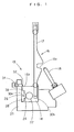
- FIG. 1 shows a first embodiment of the present invention.
- a reed retaining device 10 of a fluid-jet loom is structured, to be a piece, with a reed 16 including a plurality of thin reed dents 12, and a retaining member 14 for retaining these reed dents 12.
- the reed dents 12 are arranged at regular intervals, and the front and back sides of the reed dent 12 are provided to be parallel to the open surface of the warp.
- the reed dent 12 of the present embodiment is formed with a weft guiding section 16a, through which the weft passes due to the fluid jet.
- the reed retaining device 10 of the fluid-jet loom of the present embodiment is structured, to be a piece, in the retaining member 14 of the reed 16 attached to a reed retainer 20, which is swingably attached to the loom for swinging motion in a predetermined manner by a driving mechanism (not shown).
- the retaining member 14 is formed with, along the longitudinal direction of the reed 16, a cylindrical pressurizing tube section 22 to which pressurized compressed air is filled.
- a short cylindrical cylinder section 24 laterally extending at predetermined intervals.
- a piston member 26 being a bias member is engaged.
- a head section 28 is so formed as to be larger in diameter.
- the piston member 26 is so structured as to move in the direction orthogonal to the longitudinal direction of the reed 16 responding to the fluid pressure applied to the pressurizing tube section 22.
- the reed retainer 20 is formed with an accommodating concave section 30 whose section view looks like substantially laterally-inverted C for accommodating the retaining member 14 of the reed 16 as if to sandwich the same.
- the head section 28 of the piston member 26 abuts to a side wall 30a of the accommodating concave section 30.
- the accommodating concave section 30 includes the side wall 30a for receiving the head section 28 of the piston member 26, and another side wall 30b to which the retaining member 14 is pushed in reaction to the force of the head section 28 of the piston member 26.
- an auxiliary nozzle 18 is attached in the longitudinal direction of the reed retainer 20 at an approximate interval.
- the reed retainer 20 to prevent the reed 16 from being off, has a stopper 32 abutting to an upper corner section 14a of the retaining member 14 of the reed dent 12, and protruding in such a manner as to be orthogonal to the direction to which the reed 16 is removed.
- the stopper 32 is biased by a coil spring 34 to the protruding direction so as to freely movable in and out.
- a pipe 36 located in the plant for compressed air is provided to be connectable. Connection thereof is established to a compressor 42 for the compressed air via a control valve 38, and a check valve 40.
- the reed 16 may be retained through constant application of pressure.
- a sensor may be provided for detecting the pressure in the pressurizing tube section 22. This is to go through a process of stopping the loom if the retaining pressure is detected as low due to air leakage, for example.
- the piston member 26 is attached to the cylinder section 24 that is passing through from the pressurizing tube section 22.
- the retaining member 14 is engaged in the accommodating concave section 30 of the reed retainer 20.
- the pipe 36 for the compressed air is connected to a connector 44 provided at the end of the pressurizing tube section 22 of the retaining member 14.
- an opening/close signal is input to the control valve 38. This opens the control valve 38, and the pressure of the compressed air is applied into the pressurizing tube section 22.
- the piston member 26 is pushed sideways in the cylinder section 24, and the head section 28 pushes the side wall 30a of the accommodating concave section 30.
- the other end of the retaining member 14 is pushed to the side wall 30b of the accommodating concave section 30, and thus the retaining member 14 is securely fixed in the accommodating concave section 30.
- the stopper 32 prevents the retaining member 14 from being removed once moved down into the reed retainer 20, by then protruding, for engagement, from the upper corner section 14a of the retaining member 14 in the condition that the retaining member 14 is engaged in the accommodating concave section 30.
- the reed 16 can be securely fixed to the reed retainer 20 with ease and reliability, successfully achieving efficient reed change.
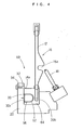
- a reed retaining device 50 of a fluid-jet loom in a second embodiment of the present invention uses the reed 16 of a general type, and a retaining member 54 of the reed dents 12 is so structured that the section view thereof looks like substantially laterally-inverted C, which is the general structure.
- the accommodating concave section 30 of the reed retainer 20 accommodates, in the longitudinal direction, a long-length pressurizing member 56 including the pressurizing tube section 22.
- the pressurizing member 56 is formed with, along the longitudinal direction of the reed 16, the cylindrical pressurizing tube section 22 to be pressurized by compressed air.
- the short cylindrical cylinder section 24 laterally extending at predetermined intervals.
- the piston member 26 being a bias member is engaged.
- the head section 28 is so formed as to be larger in diameter.
- the piston member 26 is so structured as to move in the direction orthogonal to the longitudinal direction of the reed 16 responding to compressed air pressure to be applied to the pressurizing tube section 22.
- the effects same as above first embodiment can be favorably achieved.
- the existing reed 16 can be used, and the retaining member 54 for retaining the reed dents 12 does not have to be newly provided.
- the reed retainer 20 and the pressurizing member 56 are the reed retainer 20 and the pressurizing member 56, rather easing a manufacturing process.
- a reed retaining device 60 of a fluid-jet loom in a third embodiment of the present invention.
- a pressurizing tube section 62 arranged in a retaining member 64 of the reed dents 12 is formed in such a manner that the section view thereof is annular, i.e., U-shaped.
- a bias member 66 being hollow made of rubber, for example, sealed in the pressurizing tube section 62. The bias member 66 presses the side wall 30a of the accommodating concave section 30, and the other side plane of the retaining member 64 is pushed to the side wall 30b of the accommodating concave section 30, thereby achieving secured fixation.
- the bias member 66 is a slim and long member sealed as rubber, for example, to evenly apply the retaining force in the longitudinal direction, thereby biasing the retaining member 64 in its entirety towards the side wall 30b of the accommodating concave section 30.
- the retaining member 64 of the reed 16 may be shaped by separating from the pressurizing tube section 62. This allows the existing reed 16 to be used.
- the reed retaining device of the fluid-jet loom of the present invention is not restrictive to the above embodiments, and any fluid used for pressurization may be hydraulic pressure other than compressed air, and any fluid will do as long as appropriate.
Landscapes
- Engineering & Computer Science (AREA)
- Textile Engineering (AREA)
- Looms (AREA)
Abstract
Description
Claims (4)
- A reed retaining device of a fluid-jet loom including a reed retainer (20) for sandwiching a retaining member (14,54,64) of a reed (16), the device comprising:a pressurizing tube section (22) formed between the retaining member (14) of a reed dent (16) and the reed retainer (20) in a longitudinal direction of the reed (16) for filling with a pressurizing fluid; a bias member (26) capable of being displaced in a direction orthogonal to the longitudinal direction of the reed (16) in response to fluid pressure applied to the pressurizing tube section (22) and a reception section (30) for retaining the retaining member (14) of the reed dent in response to a force of the bias member (26).
- The reed retaining device of the fluid-jet loom according to claim 1, wherein the pressurizing tube section (22) and the bias member (26) are provided in the retaining member of the reed dent.
- The reed retaining device of the fluid-jet loom according to claim 1, wherein the pressurizing tube section (22) and the bias member are located in an accommodating concave section for accommodating the retaining member of the reed dent of the reed retainer, and provided to a pressurizing member (56) separately from the retaining member (54).
- The reed retaining device of the fluid-jet loom according to claim 2 or 3, wherein the reed retainer (14) is provided with a stopper (34) abutting the retaining member (14) of the reed dent or the pressurizing member, and protruding in such a manner as to be orthogonal to a removal direction to prevent the reed (16) from being removed.
Applications Claiming Priority (2)
| Application Number | Priority Date | Filing Date | Title |
|---|---|---|---|
| JP2002265517A JP2004100105A (en) | 2002-09-11 | 2002-09-11 | Reed holding device for fluid jet loom |
| JP2002265517 | 2002-09-11 |
Publications (2)
| Publication Number | Publication Date |
|---|---|
| EP1400618A2 true EP1400618A2 (en) | 2004-03-24 |
| EP1400618A3 EP1400618A3 (en) | 2004-04-21 |
Family
ID=31944489
Family Applications (1)
| Application Number | Title | Priority Date | Filing Date |
|---|---|---|---|
| EP03255657A Withdrawn EP1400618A3 (en) | 2002-09-11 | 2003-09-10 | Reed retaining device of fluid-jet loom |
Country Status (3)
| Country | Link |
|---|---|
| EP (1) | EP1400618A3 (en) |
| JP (1) | JP2004100105A (en) |
| CN (1) | CN1490451A (en) |
Cited By (1)
| Publication number | Priority date | Publication date | Assignee | Title |
|---|---|---|---|---|
| CN102704154A (en) * | 2012-06-01 | 2012-10-03 | 绍兴市水富纺织器材有限公司 | Irregularly-shaped reed shaping clamp for jet loom |
Families Citing this family (1)
| Publication number | Priority date | Publication date | Assignee | Title |
|---|---|---|---|---|
| CN112108624B (en) * | 2020-08-25 | 2021-11-26 | 广东鸿图科技股份有限公司 | Vacuum casting system and using method |
Family Cites Families (2)
| Publication number | Priority date | Publication date | Assignee | Title |
|---|---|---|---|---|
| CS229310B1 (en) * | 1982-03-29 | 1984-06-18 | Cech Miloslav | Device for weft beat-up on weaving machines |
| DE3714847C1 (en) * | 1987-05-05 | 1988-07-14 | Dornier Gmbh Lindauer | Slay with a longitudinal groove extending in it and receiving the foot part of a reed |
-
2002
- 2002-09-11 JP JP2002265517A patent/JP2004100105A/en active Pending
-
2003
- 2003-09-10 CN CNA031584845A patent/CN1490451A/en active Pending
- 2003-09-10 EP EP03255657A patent/EP1400618A3/en not_active Withdrawn
Cited By (1)
| Publication number | Priority date | Publication date | Assignee | Title |
|---|---|---|---|---|
| CN102704154A (en) * | 2012-06-01 | 2012-10-03 | 绍兴市水富纺织器材有限公司 | Irregularly-shaped reed shaping clamp for jet loom |
Also Published As
| Publication number | Publication date |
|---|---|
| JP2004100105A (en) | 2004-04-02 |
| CN1490451A (en) | 2004-04-21 |
| EP1400618A3 (en) | 2004-04-21 |
Similar Documents
| Publication | Publication Date | Title |
|---|---|---|
| US4315425A (en) | Clamping device for fastening a tool to a tool holder | |
| US4509409A (en) | Pump arrangement for a linear fluid operated device | |
| KR101013968B1 (en) | Vehicle Glass Mounting Device | |
| US3800664A (en) | Impact tools or apparatus | |
| US5050686A (en) | Percussion drill | |
| US7178560B2 (en) | Device and method for inserting weft threads in a weaving machine, and thread clamp used therewith | |
| JP2004100105A (en) | Reed holding device for fluid jet loom | |
| WO2003076704A3 (en) | Pneumatic thread tensioner and thread handling system | |
| EP1442166B1 (en) | Method and device for supplying weft thread in a weaving machine | |
| CN101023208A (en) | Jet-weaving machine, particularly an air jet-weaving machine, with a clamping device in the mixing tube | |
| CA1054488A (en) | Pneumatic picking mechanism for looms | |
| US6109307A (en) | Thread clamping device figuring weft threads on jacquard machines | |
| KR20040089504A (en) | Improved-operation compact gripper for weaving looms | |
| US20050236062A1 (en) | Method for holding taut a weft thread and a loom for carrying out said method | |
| KR101190721B1 (en) | Shedding Mechanism and a loom provided with said shed | |
| RU1782849C (en) | Walking robot for transferring objects over randomly space-oriented surface | |
| US6000448A (en) | Delimber system | |
| CN1033850A (en) | The a pair of weft grippers that is used for shuttleless loom | |
| KR20200126894A (en) | Warp knitting machine | |
| US4029130A (en) | Weft yarn gripping element for looms | |
| EP1266986B1 (en) | Weft yarn clamp for clamping and releasing weft yarns of a weaving machine | |
| JPH0332541Y2 (en) | ||
| CN213206236U (en) | Bolt telescopic positioning device with quick reset spring arranged in oil cylinder | |
| AU2003269683A1 (en) | Method for holding a weft yarn, and a jet weaving machine, particularly serving to carry out this method | |
| EP1314805A3 (en) | A method of weft braking when picking the weft through a shed of a pneumatic weaving machine, device for carrying out the method and a braking jet |
Legal Events
| Date | Code | Title | Description |
|---|---|---|---|
| PUAI | Public reference made under article 153(3) epc to a published international application that has entered the european phase |
Free format text: ORIGINAL CODE: 0009012 |
|
| PUAL | Search report despatched |
Free format text: ORIGINAL CODE: 0009013 |
|
| AK | Designated contracting states |
Kind code of ref document: A2 Designated state(s): AT BE BG CH CY CZ DE DK EE ES FI FR GB GR HU IE IT LI LU MC NL PT RO SE SI SK TR |
|
| AX | Request for extension of the european patent |
Extension state: AL LT LV MK |
|
| AK | Designated contracting states |
Kind code of ref document: A3 Designated state(s): AT BE BG CH CY CZ DE DK EE ES FI FR GB GR HU IE IT LI LU MC NL PT RO SE SI SK TR |
|
| AX | Request for extension of the european patent |
Extension state: AL LT LV MK |
|
| RIC1 | Information provided on ipc code assigned before grant |
Ipc: 7D 03D 49/62 B Ipc: 7D 03D 49/60 A |
|
| AKX | Designation fees paid | ||
| REG | Reference to a national code |
Ref country code: DE Ref legal event code: 8566 |
|
| STAA | Information on the status of an ep patent application or granted ep patent |
Free format text: STATUS: THE APPLICATION IS DEEMED TO BE WITHDRAWN |
|
| 18D | Application deemed to be withdrawn |
Effective date: 20041022 |