EP1400417A1 - Buckle device - Google Patents
Buckle device Download PDFInfo
- Publication number
- EP1400417A1 EP1400417A1 EP02708649A EP02708649A EP1400417A1 EP 1400417 A1 EP1400417 A1 EP 1400417A1 EP 02708649 A EP02708649 A EP 02708649A EP 02708649 A EP02708649 A EP 02708649A EP 1400417 A1 EP1400417 A1 EP 1400417A1
- Authority
- EP
- European Patent Office
- Prior art keywords
- ejector
- tongue
- posture
- tongue members
- contact
- Prior art date
- Legal status (The legal status is an assumption and is not a legal conclusion. Google has not performed a legal analysis and makes no representation as to the accuracy of the status listed.)
- Withdrawn
Links
- 230000037431 insertion Effects 0.000 claims abstract description 133
- 238000003780 insertion Methods 0.000 claims abstract description 133
- 230000001105 regulatory effect Effects 0.000 claims abstract description 12
- 238000001125 extrusion Methods 0.000 claims description 19
- 239000012634 fragment Substances 0.000 description 12
- 230000033228 biological regulation Effects 0.000 description 9
- 239000000758 substrate Substances 0.000 description 8
- 239000011347 resin Substances 0.000 description 6
- 229920005989 resin Polymers 0.000 description 6
- 238000010586 diagram Methods 0.000 description 5
- 239000002184 metal Substances 0.000 description 4
- 230000002093 peripheral effect Effects 0.000 description 4
- 230000000366 juvenile effect Effects 0.000 description 3
- 208000027418 Wounds and injury Diseases 0.000 description 2
- 230000006378 damage Effects 0.000 description 2
- 208000014674 injury Diseases 0.000 description 2
- 230000001629 suppression Effects 0.000 description 2
- 206010039203 Road traffic accident Diseases 0.000 description 1
- 238000005452 bending Methods 0.000 description 1
- 230000007547 defect Effects 0.000 description 1
- 238000006073 displacement reaction Methods 0.000 description 1
- 230000002401 inhibitory effect Effects 0.000 description 1
- 238000000465 moulding Methods 0.000 description 1
- 238000000926 separation method Methods 0.000 description 1
- 230000008961 swelling Effects 0.000 description 1
Images


Classifications
-
- A—HUMAN NECESSITIES
- A44—HABERDASHERY; JEWELLERY
- A44B—BUTTONS, PINS, BUCKLES, SLIDE FASTENERS, OR THE LIKE
- A44B11/00—Buckles; Similar fasteners for interconnecting straps or the like, e.g. for safety belts
-
- A—HUMAN NECESSITIES
- A44—HABERDASHERY; JEWELLERY
- A44B—BUTTONS, PINS, BUCKLES, SLIDE FASTENERS, OR THE LIKE
- A44B11/00—Buckles; Similar fasteners for interconnecting straps or the like, e.g. for safety belts
- A44B11/25—Buckles; Similar fasteners for interconnecting straps or the like, e.g. for safety belts with two or more separable parts
- A44B11/2503—Safety buckles
- A44B11/2546—Details
- A44B11/2549—Fastening of other buckle elements to the main buckle
-
- B—PERFORMING OPERATIONS; TRANSPORTING
- B60—VEHICLES IN GENERAL
- B60N—SEATS SPECIALLY ADAPTED FOR VEHICLES; VEHICLE PASSENGER ACCOMMODATION NOT OTHERWISE PROVIDED FOR
- B60N2/00—Seats specially adapted for vehicles; Arrangement or mounting of seats in vehicles
- B60N2/24—Seats specially adapted for vehicles; Arrangement or mounting of seats in vehicles for particular purposes or particular vehicles
- B60N2/26—Seats specially adapted for vehicles; Arrangement or mounting of seats in vehicles for particular purposes or particular vehicles for children
- B60N2/28—Seats readily mountable on, and dismountable from, existing seats or other parts of the vehicle
- B60N2/2803—Adaptations for seat belts
-
- Y—GENERAL TAGGING OF NEW TECHNOLOGICAL DEVELOPMENTS; GENERAL TAGGING OF CROSS-SECTIONAL TECHNOLOGIES SPANNING OVER SEVERAL SECTIONS OF THE IPC; TECHNICAL SUBJECTS COVERED BY FORMER USPC CROSS-REFERENCE ART COLLECTIONS [XRACs] AND DIGESTS
- Y10—TECHNICAL SUBJECTS COVERED BY FORMER USPC
- Y10T—TECHNICAL SUBJECTS COVERED BY FORMER US CLASSIFICATION
- Y10T24/00—Buckles, buttons, clasps, etc.
- Y10T24/45—Separable-fastener or required component thereof [e.g., projection and cavity to complete interlock]
- Y10T24/45005—Separable-fastener or required component thereof [e.g., projection and cavity to complete interlock] with third detached member completing interlock [e.g., hook type]
- Y10T24/45079—Belt, strap, harness, etc.
- Y10T24/45084—Belt, strap, harness, etc. for safety belt buckle, strap, harness, etc.
-
- Y—GENERAL TAGGING OF NEW TECHNOLOGICAL DEVELOPMENTS; GENERAL TAGGING OF CROSS-SECTIONAL TECHNOLOGIES SPANNING OVER SEVERAL SECTIONS OF THE IPC; TECHNICAL SUBJECTS COVERED BY FORMER USPC CROSS-REFERENCE ART COLLECTIONS [XRACs] AND DIGESTS
- Y10—TECHNICAL SUBJECTS COVERED BY FORMER USPC
- Y10T—TECHNICAL SUBJECTS COVERED BY FORMER US CLASSIFICATION
- Y10T24/00—Buckles, buttons, clasps, etc.
- Y10T24/45—Separable-fastener or required component thereof [e.g., projection and cavity to complete interlock]
- Y10T24/45225—Separable-fastener or required component thereof [e.g., projection and cavity to complete interlock] including member having distinct formations and mating member selectively interlocking therewith
- Y10T24/45602—Receiving member includes either movable connection between interlocking components or variable configuration cavity
- Y10T24/45607—Receiving member includes either movable connection between interlocking components or variable configuration cavity with additional cavity for engaging different projection
- Y10T24/45613—Receiving member includes either movable connection between interlocking components or variable configuration cavity with additional cavity for engaging different projection having common means actuating or releasing interlocking components or surfaces
- Y10T24/45618—Receiving member includes either movable connection between interlocking components or variable configuration cavity with additional cavity for engaging different projection having common means actuating or releasing interlocking components or surfaces and interlocking with independently associated or dissociated projection members
Definitions
- the present invention relates to an improvement of a buckle apparatus, used for a child seat or the like, having a system of substantially simultaneously inserting and mounting a pair of tongue members.
- a child seat mounted on a seat of an automobile is used in order to protect a juvenile in the automobile against injury or mitigate the injury at the time of a traffic accident or the like by the automobile.
- an end of a crotch webbing is fixed to the front center of a seat portion of the child seat and a buckle body is mounted on the other end of this crotch webbing, for example.
- tongue members are mounted on webbings attached to extend over the right and left shoulders and the right and left hips of a juvenile sitting on the seat portion of the child seat respectively. It is so structured that the pair of tongue members are inserted into the buckle body thereby disengageably engaging with each other.
- This type of disengageable buckle apparatus includes the one disclosed in Japanese Patent Application Laying-Open Gazette No. 8-70912, which has been brought into a structure comprising a pair of tongue members, an engaging member rotatably arranged in a buckle body for disengageably engaging with the respective tongue members, an ejector urged by an extrusion spring for urging the respective tongue members in a dissociative direction and a regulation plate inhibiting rotation of the engaging member in the engaging direction with respect to the tongue members when only one tongue member is inserted into the buckle body.
- the regulation plate is rotated by the tongue member to inhibit rotation of the engaging member in the engaging direction so that no locked state resulting from engagement of the tongue member is attained when inserting only one tongue member into the buckle body and so structured that the regulation plate does not rotate but the engaging member engages with both tongue members so that an excellent locked state is attained when simultaneously inserting the pair of tongue members, to be brought into a structure aiming at improvement of reliability of the locked states on the side of the tongue members and the side of the buckle body.
- the buckle apparatus disclosed in the aforementioned conventional gazette is a system separately comprising the rotatably supported regulation plate, and there has been such a defect that the number of components such as the regulation plate and a plurality of springs for setting the initial position of the regulation plate increases to result in a high cost.
- An object of the present invention is to provide a buckle apparatus having a compact and simple structure by suppressing increase of the number of components.
- a buckle apparatus wherein an ejector comprised in a buckle body is press-operated against urging force of an extrusion spring due to insertion of a pair of tongue members into the buckle body while an engaging member disengageably engaging with the tongue members due to arrival of the tongue members on an engaging position is comprised in the buckle body for urging the tongue members in a dissociative direction by the extrusion spring through the ejector due to release of the engagement of the tongue members and the engaging member is brought into such a structure that such insertion control means that the ejector is subjected to the press operation in an insertion allowing posture to allow insertion of the respective tongue members up to the engaging position when the pair of tongue members are substantially simultaneously subjected to the insertion while the press operation is regulated by posture tilting of the ejector to suppress insertion of the tongue members up to the engaging position when only one said tongue member is subjected to the insertion is provided in the buckle body.
- insertion of the tongue members is restricted by posture tilting of the ejector, whereby a buckle apparatus having a compact and simple structure can be advantageously provided while suppressing increase of the number of components.
- the insertion control means consists of a frame member having a guide rail part slidingly guiding the ejector in the said insertion allowing posture to be reciprocative along the direction of the press operation and a stopper part separably coming into contact with the ejector in the posture tilting from the insertion allowing posture for regulating movement in the direction of the press operation, and the said stopper part is brought into a structure provided on the guide rail part.
- a tongue contact part of the ejector coming into contact with the both tongue members in the press operation is brought into a structure formed in a sharp shape toward the dissociative direction.
- insertion side end surfaces of the pair of tongue members coming into contact with the ejector for performing the press operation are brought into structures mutually inwardly inclinatorily formed.
- the ejector can be stably held on central positions of both tongue members and the ejector can be stably press-operated in the insertion allowing posture along the insertion direction thereof to be more reliably engaged with the engaging member when substantially simultaneously inserting both tongue members.
- a posture holding guide separably coming into contact with the ejector urged by the extrusion spring for holding the ejector in the insertion allowing posture in an insertion standby state for the tongue members is brought into a structure provided on the frame member.
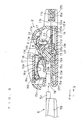
- the buckle apparatus is structured by a buckle body 2 mounted on an end of a crotch webbing 1 fixed to a seat portion of a child seat and a pair of tongue members 5 and 6 mounted on webbings 3 and 4 attached to extend over the right and left shoulders and the right and left hips of a juvenile sitting on the seat portion of the child seat respectively, and so structured that mutually disengageably engaging locked states are obtained by inserting these tongue members 5 and 6 into the buckle body 2, as shown in Fig. 1 to Fig. 4.
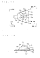
- the respective tongue members 5 and 6 are formed by molding metal plates 7 and 8 formed in proper shapes with resin and comprise webbing mounting parts 5b and 6b having webbing insertion holes 5a and 6a on/to which the webbings 3 and 4 are insertionally mounted/fixed respectively on single sides, while tongue parts 5c and 6c substantially in the form of flat plates inserted into the buckle body 2 are comprised on second sides respectively.
- Locating projections 5d and 5e are formed on one side surface and the upper surface of one tongue part 5c respectively, in order to mutually arrange the respective tongue parts 5c and 6c side-by-side to be simultaneously insertable into the buckle body 2.
- Engaging concavities 6e and 6f in which the locating projections 5d and 5e are disengageably engaged respectively are formed on one side surface of the opposite tongue part 6c and a side of the upper surface closer to the lower surface of an extension part 6d respectively.
- Rectangular engaging holes 5g and 6g in which an engaging member 10 shown in Fig. 5 to Fig. 9 and Fig. 19 to Fig. 21 is engageably engaged are formed on the respective tongue parts 5c and 6c respectively.
- the metal plates 7 and 8 on the peripheral edge portions of the respective engaging holes 5g and 6g and portions from the respective engaging holes 5g and 6g to forward ends of the tongue members 5 and 6 along the insertion direction are exposedly structured.
- the buckle body 2 comprises an upper cover body 11 and a lower cover body 12 brought into shapes vertically divided into two, so that the engaging members 10 disengageably engaged with the inserted tongue parts 5c and 6c, an ejector 13 ejecting the tongue parts 5c and 6c, an extrusion spring 14 urging the ejector 13 in an extrusive direction, i.e., a dissociative direction P, a frame member 15 supporting the engaging member 10, the ejector 13, the extrusion spring 14 etc., a disengagement button 16 releasing the engagement of the tongue parts 5c and 6c and the engaging member 10 and a display member 17 displaying the engaging state of the tongue parts 5c and 6c and the engaging member 10 are storedly attached between both cover bodies 11 and 12.
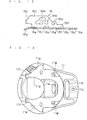
- the lower cover body 12 is molded out of resin or the like, and a webbing insertion hole 12a on/to which the crotch webbing 1 is insertionally mounted/fixed is formed and a screw insertion hole 12b for fixing the upper cover body 11 and the frame member 15 to each other is formed on an end of the lower cover body 12, as also shown in Fig. 10.
- the other end of the lower cover body 12 is rendered a tongue insertion part 19 into which the tongue parts 5c and 6c are inserted, while engaging walls 12c are uprightly provided on both side edge portions of the lower cover body 12 located on both sides of the tongue insertion part 19 and stop parts 12d projecting outward are projectingly provided on upper edge portions of the respective engaging walls 12c respectively.
- an elongated ejector guide groove 12e having a proper width is formed on the bottom surface of the lower cover body 12 from the central portion in the direction of the webbing insertion hole 12a and a stop concavity 12f on which a stop fragment part 15a projectingly formed on the frame member 15 is stopped is formed on the side of the tongue insertion part 19 while stop parts 12g disengageably engaged with the upper surfaces of both side edge portions of the frame member 15 are formed on both sides of the webbing insertion hole 12a respectively.
- the frame member 15 consists of a properly bent/formed metal plate, and is brought into a structure comprising a substantially rectangular substrate part 15b, the said stop fragment part 15a projectingly formed on a longitudinal end of the substrate part 15b and support wall parts 15c oppositely uprightly provided from both side edge portions of the substrate part 15b respectively, as also shown in Fig. 11 and Fig. 12.
- the portion between these support wall parts 15c is structured as a tongue insertion path 19a for both tongue parts 5c and 6c inserted from the tongue insertion part 19.
- the substrate part 15b is formed with a webbing insertion hole 15d and a screw insertion hole 15e rendered communicative with the webbing insertion hole 12a and the screw insertion hole 12b of the lower cover body 12, while a guide hole 15f guiding the ejector 13 along the longitudinal direction is formed on the central portion.
- the upper cover body 11 is molded out of resin or the like in order to cover the upper surface side of the lower cover body 12, formed with stop cavities 11a in which the respective stop parts 12d of the lower cover body 12 are disengageably stopped, and formed with a webbing insertion hole 11b and a screw insertion hole 11c rendered communicative with the webbing insertion hole 12a and the screw insertion hole 12b of the lower cover body 12, as also shown in Fig. 13.
- the side of the upper cover body 11 closer to the tongue insertion part 19 is formed with an operational opening 11d of a corresponding shape in which the cancel button 16 is rendered exposed and formed with a display window 11e located between the operational opening 11d and the webbing insertion hole 11b so that the display member 17 can be visually recognized.
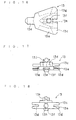
- the ejector 13 is formed into a substantially triangular shape in plan view by resin or the like as also shown in Fig. 14 to Fig. 18, and comprises a slide base part 13a arranged under the substrate part 15b of the frame member 15, a slide guide part 13b located in the guide hole 15f on the upper surface side of the slide base part 13a while having a height substantially identical to the thickness of the substrate part 15b, a slide vane part 13c extensionally formed on the upper surface side of the slide guide part 13b from an end opposite to the tongue insertion part 19 on an upper area of the slide base part 13a on the upper side of the substrate part 15b and a tongue contact part 13d projectingly formed upwardly beyond the upper surface of the slide guide part 13b on the central portion of the ejector 13.
- rail groove parts 13g in which both guide rail parts 15g structured by both side edge portions of the guide hole 15f in the frame member 15 shown in Fig. 5, Fig. 7, Fig. 9 and Fig. 11 are slidably engaged respectively are structured between the upper and lower slide vane part 13c and slide base part 13a.
- An end of the slide base part 13a projecting beyond the slide guide part 13b in the direction of the tongue insertion part 19 is rendered a narrow lingual part 13e, and a boss part 13f engaged in the ejector guide groove 12e and slidable along the longitudinal direction thereof is comprised on the lower surface side of the central portion of the slide base part 13a.
- the boss part 13f is substantially cylindrically formed and its end surface closer to the tongue insertion part 19 is formed in a flat surface as shown in Fig. 16, to separably come into contact with a flat surface on the side of the ejector guide groove 12e shown in Fig. 10 closer to the tongue insertion part 19.
- the tongue contact part 13d is formed in a sharp triangular shape toward the dissociative direction P as shown in Fig. 5, Fig. 7, Fig. 9 and Fig. 14, and so structured that its sharp forward end portion is located on the centers of both tongue parts 5c and 6c inserted from the tongue insertion part 19.
- insertion side end surfaces 5h and 6h of both tongue parts 5c and 6c are mutually inwardly inclinatorily formed, and so structured that the said insertion side end surfaces 5h and 6h separably come into contact with both side surfaces of the tongue contact part 13d brought into the triangular shape.
- a spring bearing hole 13h in the form of a circular hole is formed on an end surface of the ejector 13 opposite to the lingual part 13e as shown in Fig. 14 to Fig. 16 and Fig. 18 and the extrusion spring 14 consisting of a coil spring is compressively mounted between the same and a spring support projection 15h comprised on the frame member 15 as shown in Fig. 5 to Fig. 9, so that the ejector 13 is elastically urged in the direction of the tongue insertion part 19, i.e., in the dissociative direction P due to the urging force of this extrusion spring 14.
- an edge portion of the guide hole 15f closer to the tongue insertion part 19 is formed in an arcuate shape swelling out in the direction of the tongue insertion part 19 on the width-directional central portion and structured as a posture holding guide 15j guiding the forward end portion of the slide guide part 13b to the width-directional center in an insertion standby state where the respective tongue parts 5c and 6c are uninserted into the ejector 13 urged by the extrusion spring 14, as shown in Fig. 5 and Fig. 11.
- the forward end portion of the slide guide part 13b slidably coming into contact with the posture holding guide 15j is structured in a proper polygonal shape projecting on the width-directional central portion or an arcuate shape corresponding to the posture holding guide 15j. In this case, it is also brought into contact with the flat surface of the ejector guide groove 12e closer to the tongue insertion part 19 and the flat surface on the boss part 13f of the ejector 13.
- the ejector 13 When both tongue parts 5c and 6c are substantially simultaneously inserted from the tongue insertion part 19 in this insertion standby state, the ejector 13 is structured to be press-operated along the insertion direction Q of both tongue parts 5c and 6c in the state of the posture.
- the ejector 13 is structured to stably stand by in an insertion allowing posture in the insertion standby state.
- an upwardly tilting engaging member holding guide 13j and a downwardly tilting display member holding guide 13k are comprised respectively along the insertion direction Q of both tongue parts 5c and 6c.
- stopper parts 15k separably coming into contact with the slide guide part 13b due to posture tilting around the boss part 13f from the insertion allowing posture of the ejector 13 for regulating movement in the direction of the press operation, i.e., in the insertion direction Q are extensionally formed on both guide rail parts 15g respectively.
- the stopper parts 15k are extended substantially in the form of trapezoids and comprised in a pair separably in the insertion direction Q for the respective tongue parts 5c and 6c.
- Both side portions of the slide guide part 13b closer to the tongue insertion part 19 are formed in the shape of narrow constrictions, in order to allow the posture tilting of the ejector 13.
- the engaging member 10 is prepared by bending/forming a metal plate into a proper shape by press working or the like, and structured by a rectangular flat support fragment part 10a swingably supported between holding holes 15m formed on both support wall parts 15c of the frame member 15 respectively, a disengagement operational fragment part 10b upwardly inclinatorily extensionally provided from an edge of the support fragment part 10a closer to the tongue insertion part 19 and engaging projections 10c downwardly projectingly formed on the support fragment part 10a respectively in correspondence to the positions of the engaging holes 5g and 6g of the respective tongue parts 5c and 6c inserted along the tongue insertion path 19a and disengageably engaged in the respective engaging holes 5g and 6g.
- the disengagement button 16 is molded out of resin or the like, and structured by a press operation part 16a substantially circular in plan view, spindle parts 16b comprised to extend on both side portions on a side of the press operation part 16a closer to the tongue insertion part 19, return regulation vanes 16c extensionally formed along both side portions of the outer side surface of the press operation part 16a respectively and operational projections 16d downwardly projectingly formed on both sides of intermediate parts of the respective tongue parts 5c and 6c along the insertion direction on the lower surface side of the press operation part 16a respectively.
- the upper surface of the press operation part 16a is properly formed with non-slip projections 16e serving as non-slips in the press operation.
- the peripheral surfaces of the spindle parts 16b located on the lower surface side of the press operation part 16a are partially notchedly formed so that a fitting part 21a of a properly bent/formed plate spring 21 shown in Fig. 26 and Fig. 27 is fitted in the spindle parts 16b of these portions as shown in Fig. 6 and Fig. 8, so that a fitted and uprightly formed stop fragment 21b is prevented from displacement and stopped on the spindle parts 16b.
- the spindle parts 16b projecting on both sides of the disengagement button 16 are relatively rotatably supported by support concavities 15n comprised on ends of both support wall parts 15c of the frame member 15 closer to the tongue insertion part 19 respectively and support concavities 11f formed on the lower surface of the upper cover body 11 closer to the tongue insertion part 19 respectively.
- a push-down part 21c on a bent end of the plate spring 21 is elastically brought into contact with the upper surface of an end of the support fragment part 10a of the engaging member 10 opposite to the disengagement operational fragment part 10b and brought into a structure making elastic urging in order to push down the end of the support fragment part 10a downward.
- the display member 17 is formed by resin or the like, and comprises an arcuate display part 17a, spindle parts 17b extensionally formed on both side portions in order to support the display part 17a and a spring bearing part 17c projectingly formed on one side surface.
- the display part 17a is divided into two, i.e., an unlocked state display area A colored red and a locked state display area B colored green along the peripheral direction.
- both spindle parts 17b are relatively rotatably supported in support concavities 15p formed on both support wall parts 15c respectively in order to bush-engage the central portion of a torsion spring 23 in one spindle part 17b, bush-stop one end to the spring bearing parts 17c and compressively bring the other end onto the substrate part 15b of the frame member 15, and separation of the spindle parts 17b from the respective support concavities 15p is regulated by holding concavities 11g comprised on the lower surface of the upper cover body 11.
- This display member 17 is so structured that an edge located on the side of the display part 17a in the direction of the tongue insertion part 19 is brought into contact with the display member holding guide 13k due to the urging force of the torsion spring 23 and the unlocked state display area A is located in correspondence to the display window 11e in the insertion standby state of both tongue parts 5c and 6c, as shown in Fig. 6.
- the display member 17 in a locked state where both tongue parts 5c and 6c are inserted, the display member 17 is rotationally operated about the spindle parts 17b against the urging force of the torsion spring 23 due to relative sliding of a slide part 17d comprised on the display member 17 and the display member holding guide 13k and the locked state display area B is located in correspondence to the display window 11e, as shown in Fig. 8.
- This embodiment is structured in the aforementioned manner, and the ejector 13 is urged by the urging force of the extrusion spring 14 in the direction of the tongue insertion part 19 so that an end of the slide guide part 13b located in the direction of the tongue insertion part 19 comes into contact with the posture holding guide 15j of the frame member 15 while the flat surface of the boss part 13f is brought into contact with the flat surface of the ejector guide groove 12e and held in the insertion allowing posture press-movable along the insertion direction of both tongue parts 5c and 6c in a non-insertion state of the respective tongue parts 5c and 6c, as shown in Fig. 5 and Fig. 6.
- the engaging member 10 is held in the engaging member holding guide 13j, the engaging projections 10c are retreated upward beyond the tongue insertion path 19a, the slide part 17d comes into contact with the display member holding guide 13k in the display member 17, and the unlocked state display area A is located in the display window 11e.
- the disengagement button 16 is upwardly urged about the spindle parts 16b due to the urging force of the plate spring 21, and both return regulation vanes 16c come into contact with the peripheral edge portion of the operational opening 11d and are hold in a prescribed posture.
- the tongue contact part 13d is formed in the sharp triangular shape with respect to the dissociative direction P and the end surfaces 5h and 6h of both tongue parts 5c and 6c are mutually inwardly inclinatorily formed, whereby the ejector 13 is press-operated along the insertion direction Q under guiding by both guide rail parts 15g while maintaining its insertion allowing posture.
- the side of the engaging member 10 closer to the engaging projections 10c is downwardly operated along the engaging member holding guide 13j under the urging force by the plate spring 21.
- the slide part 17d is slid along the display member holding guide 13k and the display member 17 is rotationally operated about the spindle parts 17b against the urging force of the torsion spring 23.
- the engaging member 10 separates from the engaging member holding guide 13j when the respective engaging projections 10c come into contact with upper portions of the tongue parts 5c and 6c due to insertion of both tongue parts 5c and 6c, and the locked state where both engaging projections 10c are downwardly operated to enter the respective engaging holes 5g and 6g and engage therewith is obtained under the urging force by the plate spring 21 as shown in Fig. 7 and Fig. 8 when both tongue parts 5c and 6c are inserted and the respective engaging holes 5g and 6g reach prescribed positions.
- the display member 17 is further rotationally operated about the spindle parts 17b due to relative sliding of the display member holding guide 13k and the slide part 17d, so that the locked state display area B is located in correspondence to the position of the display window 11e and the locked state can be also visually confirmed.
- the ejector 13 deviates from the orbit subjected to ordinary press operation due to posture tilting resulting from this rotation of the ejector 13, so that the end surface of the slide guide part 13b opposite to the tongue insertion part 19 in the ejector 13 comes into contact with the stopper parts 15k and the press operation is regulated even if the tongue part 6c is further force-operated from this state.
- the ejector 13 further posture-tilts so that the slide guide part 13b on the side closer to the constricted tongue insertion part 19 also comes into contact with the stopper parts 15k, and the press operation in the normal direction is regulated also from this point while subsequent posture tilting is also regulated, so that the tongue part 6c cannot be further inserted.
- the tongue part 6c cannot be inserted up to the engaging position where the engaging hole 6g corresponds to the engaging projection 6g but unprepared engagement between the engaging hole 6g and the engaging projections 10c can be prevented so that false mounting by only one can be effectively prevented.
- a person mounting the tongue members 5 and 6 can sensuously fractionate that the insertion stroke for the tongue parts 5c and 6c in engagement and the insertion stroke in non-engagement obviously differ from each other, and can quickly recognize that the tongue members 5 and 6 and the buckle body 2 are in a non-engaging state.
- the ejector 13 posture-tilts in the direction opposite to the above and similarly operates.
- the insertion control means regulating the movement of the tongue parts 5c and 6c in the insertion direction is formed by only the single ejector 13 and the frame member 15 slide-guiding the same, the number of components may not be increased dissimilarly to the prior art, it is excellent in assembling workability with a simple structure, and cost reduction can be attained.
- the ejector 13 is posture-tilted from the ordinary insertion allowing posture so that movement of the ejector 13 in the insertion direction Q can be effectively suppressed, and the buckle body 2 may not be largely structured but compactification can be attained as the whole of the buckle apparatus.
- the tongue contact part 13d of the ejector 13 is brought into the sharp shape toward the dissociative direction P, whereby the same is readily posture-tilted from the insertion allowing posture when only one tongue part 5c or 6c is inserted so that suppression performance not unpreparedly inserting only one tongue part 5c or 6c up to the engaging position with the engaging member 10 can be effectively improved.
- the end surfaces 5h and 6h of the tongue parts 5c and 6c in both tongue members 5 and 6 are mutually inwardly inclinatorily formed, whereby the tongue contact part 13d can be stably held on the central positions of both tongue parts 5c and 6c, the ejector 13 can be stably press-operated along the insertion direction Q in the insertion allowing posture and the engaging holes 5g and 6g in both tongue parts 5c and 6c and the respective engaging projections 10c of the engaging member 10 can be more reliably engaged when simultaneously inserting both tongue parts 5c and 6c.
- the ejector 13 can be stably held in the insertion allowing posture due to the contact of the slide guide member 13b with respect to the posture holding guide 15j and the contact between the flat surface of the boss part 13f and the flat surface of the ejector guide groove 12e, and the aforementioned control operation in insertion can be more stably exerted when the tongue members 5 and 6 are simultaneously inserted or only one is inserted.
- a structure integrally comprising a structure similar to the frame member 15 on the lower cover body 12 for slidably holding the ejector 13 may be employed.
Landscapes
- Engineering & Computer Science (AREA)
- Health & Medical Sciences (AREA)
- Child & Adolescent Psychology (AREA)
- General Health & Medical Sciences (AREA)
- Aviation & Aerospace Engineering (AREA)
- Transportation (AREA)
- Mechanical Engineering (AREA)
- Buckles (AREA)
Abstract
A buckle apparatus comprises insertion control means press-operating an
ejector (13) when a pair of tongue parts (5c, 6c) are simultaneously inserted into a buckle
body (2) for allowing insertion up to an engaging position between the respective tongue
parts (5c, 6c) and an engaging member (10) while regulating the press operation by
posture tilting of the ejector (13) when only one tongue part (5c, 6c) is inserted. The
insertion control means comprises a frame member (15) having a guide rail part (15g)
reciprocatively slidingly guiding the ejector (13) along the direction of the press operation
while comprising a stopper part (15k) separably coming into contact with the ejector (13)
in posture tilting from an insertion allowing posture for regulating movement in the
direction of the press operation on the guide rail part (15g).
Description
- The present invention relates to an improvement of a buckle apparatus, used for a child seat or the like, having a system of substantially simultaneously inserting and mounting a pair of tongue members.
- In recent years, a child seat mounted on a seat of an automobile is used in order to protect a juvenile in the automobile against injury or mitigate the injury at the time of a traffic accident or the like by the automobile.
- As a seat belt apparatus employed for this type of child seat, an end of a crotch webbing is fixed to the front center of a seat portion of the child seat and a buckle body is mounted on the other end of this crotch webbing, for example. Further, tongue members are mounted on webbings attached to extend over the right and left shoulders and the right and left hips of a juvenile sitting on the seat portion of the child seat respectively. It is so structured that the pair of tongue members are inserted into the buckle body thereby disengageably engaging with each other.
- This type of disengageable buckle apparatus includes the one disclosed in Japanese Patent Application Laying-Open Gazette No. 8-70912, which has been brought into a structure comprising a pair of tongue members, an engaging member rotatably arranged in a buckle body for disengageably engaging with the respective tongue members, an ejector urged by an extrusion spring for urging the respective tongue members in a dissociative direction and a regulation plate inhibiting rotation of the engaging member in the engaging direction with respect to the tongue members when only one tongue member is inserted into the buckle body.
- And it has been so structured that the regulation plate is rotated by the tongue member to inhibit rotation of the engaging member in the engaging direction so that no locked state resulting from engagement of the tongue member is attained when inserting only one tongue member into the buckle body and so structured that the regulation plate does not rotate but the engaging member engages with both tongue members so that an excellent locked state is attained when simultaneously inserting the pair of tongue members, to be brought into a structure aiming at improvement of reliability of the locked states on the side of the tongue members and the side of the buckle body.
- According to the buckle apparatus disclosed in the aforementioned conventional gazette, however, it is a system separately comprising the rotatably supported regulation plate, and there has been such a defect that the number of components such as the regulation plate and a plurality of springs for setting the initial position of the regulation plate increases to result in a high cost.
- Further, there has been such a problem that a space for rotating the regulation plate is also required to cause size increase of the overall apparatus and complication of the structure, and it is also inferior in assembling workability.
- An object of the present invention is to provide a buckle apparatus having a compact and simple structure by suppressing increase of the number of components.
- In one mode of the buckle apparatus according to the present invention, a buckle apparatus wherein an ejector comprised in a buckle body is press-operated against urging force of an extrusion spring due to insertion of a pair of tongue members into the buckle body while an engaging member disengageably engaging with the tongue members due to arrival of the tongue members on an engaging position is comprised in the buckle body for urging the tongue members in a dissociative direction by the extrusion spring through the ejector due to release of the engagement of the tongue members and the engaging member is brought into such a structure that such insertion control means that the ejector is subjected to the press operation in an insertion allowing posture to allow insertion of the respective tongue members up to the engaging position when the pair of tongue members are substantially simultaneously subjected to the insertion while the press operation is regulated by posture tilting of the ejector to suppress insertion of the tongue members up to the engaging position when only one said tongue member is subjected to the insertion is provided in the buckle body.
- According to this mode, insertion of the tongue members is restricted by posture tilting of the ejector, whereby a buckle apparatus having a compact and simple structure can be advantageously provided while suppressing increase of the number of components.
- In another mode of the buckle apparatus according to the present invention, the insertion control means consists of a frame member having a guide rail part slidingly guiding the ejector in the said insertion allowing posture to be reciprocative along the direction of the press operation and a stopper part separably coming into contact with the ejector in the posture tilting from the insertion allowing posture for regulating movement in the direction of the press operation, and the said stopper part is brought into a structure provided on the guide rail part.
- According to this mode, there is such an advantage that insertion control of the tongue members can be more effectively performed without increasing the number of components.
- In still another mode of the buckle apparatus according to the present invention, a tongue contact part of the ejector coming into contact with the both tongue members in the press operation is brought into a structure formed in a sharp shape toward the dissociative direction.
- According to this mode, there is such an advantage that the ejector readily posture-tilts when only one tongue member is inserted to be capable of improving suppression performance for not unpreparedly inserting the tongue member to the engaging position with the engaging member.
- In a further mode of the buckle apparatus according to the present invention, insertion side end surfaces of the pair of tongue members coming into contact with the ejector for performing the press operation are brought into structures mutually inwardly inclinatorily formed.
- According to this mode, there is such an advantage that the ejector can be stably held on central positions of both tongue members and the ejector can be stably press-operated in the insertion allowing posture along the insertion direction thereof to be more reliably engaged with the engaging member when substantially simultaneously inserting both tongue members.
- In a further mode of the buckle apparatus according to the present invention, a posture holding guide separably coming into contact with the ejector urged by the extrusion spring for holding the ejector in the insertion allowing posture in an insertion standby state for the tongue members is brought into a structure provided on the frame member.
- According to this mode, there is such an advantage that the ejector can be made to stably stand by in the insertion allowing posture and control operation in insertion of the tongue members can be stably exerted.
-
- Fig. 1 is an operational explanatory diagram in an embodiment of the present invention.
- Fig. 2 is a view taken along the line II-II in Fig. 1.
- Fig. 3 is a view taken along the line III-III in Fig. 1.
- Fig. 4 is an operational explanatory diagram for insertion of a tongue member.
- Fig. 5 is an operational explanatory diagram for insertion of tongue parts in a state detaching an upper cover body.
- Fig. 6 is a partially fragmented sectional view taken along the line VI-VI in Fig. 5.
- Fig. 7 is an operational explanatory diagram for insertion of the tongue parts in the state detaching the upper cover body.
- Fig. 8 is a partially fragmented sectional view taken along the line VIII-VIII in Fig. 7.
- Fig. 9 is an operational explanatory diagram for insertion of only one tongue part in the state detaching the upper cover body.
- Fig. 10 is a plan view of a lower cover body.
- Fig. 11 is a plan view of a frame member.
- Fig. 12 is a sectional view taken along the line XII-XII in Fig. 11.
- Fig. 13 is a bottom plan view of the upper cover body.
- Fig. 14 is a plan view of an ejector.
- Fig. 15 is a view taken along the line XV-XV in Fig. 14.
- Fig. 16 is a bottom plan view of the ejector.
- Fig. 17 is a view taken along the line XVII-XVII in Fig. 14.
- Fig. 18 is a view taken along the line XVIII-XVIII in Fig. 14.
- Fig. 19 is a plan view of an engaging member.
- Fig. 20 is a view taken along the line XX-XX in Fig. 19.
- Fig. 21 is a view taken along the line XXI-XXI in Fig. 19.
- Fig. 22 is a plan view of a disengagement button.
- Fig. 23 is a view taken along the line XXIII-XXIII in Fig. 22.
- Fig. 24 is a view taken along the line XXIV-XXIV in Fig. 22.
- Fig. 25 is a sectional view taken along the line XXV-XXV in Fig. 22.
- Fig. 26 is a sectional view of a plate spring.
- Fig. 27 is a plan view of the plate spring.
- Fig. 28 is a side elevational view of a display member.
- Fig. 29 is a view taken along the line XXIX-XXIX in Fig. 28.
- Fig. 30 is a rear elevational view of Fig. 29.
-
- Describing an embodiment of the buckle apparatus according to the present invention with reference to the drawings, it is structured by a
buckle body 2 mounted on an end of acrotch webbing 1 fixed to a seat portion of a child seat and a pair oftongue members tongue members buckle body 2, as shown in Fig. 1 to Fig. 4. - The
respective tongue members metal plates webbing mounting parts webbing insertion holes 5a and 6a on/to which the webbings 3 and 4 are insertionally mounted/fixed respectively on single sides, whiletongue parts buckle body 2 are comprised on second sides respectively. - Locating
projections tongue part 5c respectively, in order to mutually arrange therespective tongue parts buckle body 2.Engaging concavities projections opposite tongue part 6c and a side of the upper surface closer to the lower surface of an extension part 6d respectively. - Rectangular
engaging holes engaging member 10 shown in Fig. 5 to Fig. 9 and Fig. 19 to Fig. 21 is engageably engaged are formed on therespective tongue parts metal plates engaging holes engaging holes tongue members - The
buckle body 2 comprises anupper cover body 11 and alower cover body 12 brought into shapes vertically divided into two, so that theengaging members 10 disengageably engaged with the insertedtongue parts ejector 13 ejecting thetongue parts extrusion spring 14 urging theejector 13 in an extrusive direction, i.e., a dissociative direction P, aframe member 15 supporting theengaging member 10, theejector 13, theextrusion spring 14 etc., adisengagement button 16 releasing the engagement of thetongue parts engaging member 10 and adisplay member 17 displaying the engaging state of thetongue parts engaging member 10 are storedly attached between bothcover bodies - The
lower cover body 12 is molded out of resin or the like, and awebbing insertion hole 12a on/to which thecrotch webbing 1 is insertionally mounted/fixed is formed and ascrew insertion hole 12b for fixing theupper cover body 11 and theframe member 15 to each other is formed on an end of thelower cover body 12, as also shown in Fig. 10. The other end of thelower cover body 12 is rendered atongue insertion part 19 into which thetongue parts engaging walls 12c are uprightly provided on both side edge portions of thelower cover body 12 located on both sides of thetongue insertion part 19 andstop parts 12d projecting outward are projectingly provided on upper edge portions of the respectiveengaging walls 12c respectively.
Further, an elongatedejector guide groove 12e having a proper width is formed on the bottom surface of thelower cover body 12 from the central portion in the direction of thewebbing insertion hole 12a and astop concavity 12f on which astop fragment part 15a projectingly formed on theframe member 15 is stopped is formed on the side of thetongue insertion part 19 whilestop parts 12g disengageably engaged with the upper surfaces of both side edge portions of theframe member 15 are formed on both sides of thewebbing insertion hole 12a respectively. - The
frame member 15 consists of a properly bent/formed metal plate, and is brought into a structure comprising a substantiallyrectangular substrate part 15b, the saidstop fragment part 15a projectingly formed on a longitudinal end of thesubstrate part 15b andsupport wall parts 15c oppositely uprightly provided from both side edge portions of thesubstrate part 15b respectively, as also shown in Fig. 11 and Fig. 12. The portion between thesesupport wall parts 15c is structured as atongue insertion path 19a for bothtongue parts tongue insertion part 19. - Further, the
substrate part 15b is formed with awebbing insertion hole 15d and ascrew insertion hole 15e rendered communicative with thewebbing insertion hole 12a and thescrew insertion hole 12b of thelower cover body 12, while aguide hole 15f guiding theejector 13 along the longitudinal direction is formed on the central portion. - The
upper cover body 11 is molded out of resin or the like in order to cover the upper surface side of thelower cover body 12, formed withstop cavities 11a in which therespective stop parts 12d of thelower cover body 12 are disengageably stopped, and formed with awebbing insertion hole 11b and ascrew insertion hole 11c rendered communicative with thewebbing insertion hole 12a and thescrew insertion hole 12b of thelower cover body 12, as also shown in Fig. 13. - The side of the
upper cover body 11 closer to thetongue insertion part 19 is formed with anoperational opening 11d of a corresponding shape in which the cancelbutton 16 is rendered exposed and formed with adisplay window 11e located between theoperational opening 11d and thewebbing insertion hole 11b so that thedisplay member 17 can be visually recognized. - The
ejector 13 is formed into a substantially triangular shape in plan view by resin or the like as also shown in Fig. 14 to Fig. 18, and comprises aslide base part 13a arranged under thesubstrate part 15b of theframe member 15, aslide guide part 13b located in theguide hole 15f on the upper surface side of theslide base part 13a while having a height substantially identical to the thickness of thesubstrate part 15b, aslide vane part 13c extensionally formed on the upper surface side of theslide guide part 13b from an end opposite to thetongue insertion part 19 on an upper area of theslide base part 13a on the upper side of thesubstrate part 15b and atongue contact part 13d projectingly formed upwardly beyond the upper surface of theslide guide part 13b on the central portion of theejector 13. - Here,
rail groove parts 13g in which both guiderail parts 15g structured by both side edge portions of theguide hole 15f in theframe member 15 shown in Fig. 5, Fig. 7, Fig. 9 and Fig. 11 are slidably engaged respectively are structured between the upper and lowerslide vane part 13c andslide base part 13a. - An end of the
slide base part 13a projecting beyond theslide guide part 13b in the direction of thetongue insertion part 19 is rendered a narrowlingual part 13e, and aboss part 13f engaged in theejector guide groove 12e and slidable along the longitudinal direction thereof is comprised on the lower surface side of the central portion of theslide base part 13a. At this time, theboss part 13f is substantially cylindrically formed and its end surface closer to thetongue insertion part 19 is formed in a flat surface as shown in Fig. 16, to separably come into contact with a flat surface on the side of theejector guide groove 12e shown in Fig. 10 closer to thetongue insertion part 19. - Further, the
tongue contact part 13d is formed in a sharp triangular shape toward the dissociative direction P as shown in Fig. 5, Fig. 7, Fig. 9 and Fig. 14, and so structured that its sharp forward end portion is located on the centers of bothtongue parts tongue insertion part 19. At this time, insertionside end surfaces tongue parts side end surfaces tongue contact part 13d brought into the triangular shape. - A
spring bearing hole 13h in the form of a circular hole is formed on an end surface of theejector 13 opposite to thelingual part 13e as shown in Fig. 14 to Fig. 16 and Fig. 18 and theextrusion spring 14 consisting of a coil spring is compressively mounted between the same and aspring support projection 15h comprised on theframe member 15 as shown in Fig. 5 to Fig. 9, so that theejector 13 is elastically urged in the direction of thetongue insertion part 19, i.e., in the dissociative direction P due to the urging force of thisextrusion spring 14. - At this time, an edge portion of the
guide hole 15f closer to thetongue insertion part 19 is formed in an arcuate shape swelling out in the direction of thetongue insertion part 19 on the width-directional central portion and structured as aposture holding guide 15j guiding the forward end portion of theslide guide part 13b to the width-directional center in an insertion standby state where therespective tongue parts ejector 13 urged by theextrusion spring 14, as shown in Fig. 5 and Fig. 11. The forward end portion of theslide guide part 13b slidably coming into contact with theposture holding guide 15j is structured in a proper polygonal shape projecting on the width-directional central portion or an arcuate shape corresponding to theposture holding guide 15j. In this case, it is also brought into contact with the flat surface of theejector guide groove 12e closer to thetongue insertion part 19 and the flat surface on theboss part 13f of theejector 13. - When both
tongue parts tongue insertion part 19 in this insertion standby state, theejector 13 is structured to be press-operated along the insertion direction Q of bothtongue parts ejector 13 is structured to stably stand by in an insertion allowing posture in the insertion standby state. - On the upper surface side of the
tongue contact part 13d, an upwardly tilting engagingmember holding guide 13j and a downwardly tilting displaymember holding guide 13k are comprised respectively along the insertion direction Q of bothtongue parts - Further,
stopper parts 15k separably coming into contact with theslide guide part 13b due to posture tilting around theboss part 13f from the insertion allowing posture of theejector 13 for regulating movement in the direction of the press operation, i.e., in the insertion direction Q are extensionally formed on bothguide rail parts 15g respectively. At this time, thestopper parts 15k are extended substantially in the form of trapezoids and comprised in a pair separably in the insertion direction Q for therespective tongue parts - Both side portions of the
slide guide part 13b closer to thetongue insertion part 19 are formed in the shape of narrow constrictions, in order to allow the posture tilting of theejector 13. - As also shown in Fig. 19 to Fig. 21, the engaging
member 10 is prepared by bending/forming a metal plate into a proper shape by press working or the like, and structured by a rectangular flatsupport fragment part 10a swingably supported between holdingholes 15m formed on bothsupport wall parts 15c of theframe member 15 respectively, a disengagementoperational fragment part 10b upwardly inclinatorily extensionally provided from an edge of thesupport fragment part 10a closer to thetongue insertion part 19 and engagingprojections 10c downwardly projectingly formed on thesupport fragment part 10a respectively in correspondence to the positions of the engagingholes respective tongue parts tongue insertion path 19a and disengageably engaged in the respective engagingholes - As shown in Fig. 22 to Fig. 25, the
disengagement button 16 is molded out of resin or the like, and structured by a press operation part 16a substantially circular in plan view,spindle parts 16b comprised to extend on both side portions on a side of the press operation part 16a closer to thetongue insertion part 19, returnregulation vanes 16c extensionally formed along both side portions of the outer side surface of the press operation part 16a respectively andoperational projections 16d downwardly projectingly formed on both sides of intermediate parts of therespective tongue parts non-slip projections 16e serving as non-slips in the press operation. - As shown in Fig. 25, the peripheral surfaces of the
spindle parts 16b located on the lower surface side of the press operation part 16a are partially notchedly formed so that afitting part 21a of a properly bent/formedplate spring 21 shown in Fig. 26 and Fig. 27 is fitted in thespindle parts 16b of these portions as shown in Fig. 6 and Fig. 8, so that a fitted and uprightly formedstop fragment 21b is prevented from displacement and stopped on thespindle parts 16b. - As shown in Fig. 6 and Fig. 8, the
spindle parts 16b projecting on both sides of thedisengagement button 16 are relatively rotatably supported bysupport concavities 15n comprised on ends of bothsupport wall parts 15c of theframe member 15 closer to thetongue insertion part 19 respectively andsupport concavities 11f formed on the lower surface of theupper cover body 11 closer to thetongue insertion part 19 respectively. At this time, a push-downpart 21c on a bent end of theplate spring 21 is elastically brought into contact with the upper surface of an end of thesupport fragment part 10a of the engagingmember 10 opposite to the disengagementoperational fragment part 10b and brought into a structure making elastic urging in order to push down the end of thesupport fragment part 10a downward. - As shown in Fig. 28 to Fig. 30, the
display member 17 is formed by resin or the like, and comprises an arcuate display part 17a,spindle parts 17b extensionally formed on both side portions in order to support the display part 17a and aspring bearing part 17c projectingly formed on one side surface. The display part 17a is divided into two, i.e., an unlocked state display area A colored red and a locked state display area B colored green along the peripheral direction. - As shown by phantom lines in Fig. 28, both
spindle parts 17b are relatively rotatably supported insupport concavities 15p formed on bothsupport wall parts 15c respectively in order to bush-engage the central portion of atorsion spring 23 in onespindle part 17b, bush-stop one end to thespring bearing parts 17c and compressively bring the other end onto thesubstrate part 15b of theframe member 15, and separation of thespindle parts 17b from therespective support concavities 15p is regulated by holdingconcavities 11g comprised on the lower surface of theupper cover body 11. - This
display member 17 is so structured that an edge located on the side of the display part 17a in the direction of thetongue insertion part 19 is brought into contact with the displaymember holding guide 13k due to the urging force of thetorsion spring 23 and the unlocked state display area A is located in correspondence to thedisplay window 11e in the insertion standby state of bothtongue parts tongue parts display member 17 is rotationally operated about thespindle parts 17b against the urging force of thetorsion spring 23 due to relative sliding of aslide part 17d comprised on thedisplay member 17 and the displaymember holding guide 13k and the locked state display area B is located in correspondence to thedisplay window 11e, as shown in Fig. 8. - Mutually inwardly projecting
guide boss parts 15q are projectingly provided on bothsupport wall parts 15c of theframe member 15 as shown in Fig. 11 and Fig. 12, in order to regulate floating of insertion end sides when therespective tongue parts tongue insertion path 19a. - This embodiment is structured in the aforementioned manner, and the
ejector 13 is urged by the urging force of theextrusion spring 14 in the direction of thetongue insertion part 19 so that an end of theslide guide part 13b located in the direction of thetongue insertion part 19 comes into contact with theposture holding guide 15j of theframe member 15 while the flat surface of theboss part 13f is brought into contact with the flat surface of theejector guide groove 12e and held in the insertion allowing posture press-movable along the insertion direction of bothtongue parts respective tongue parts - The engaging
member 10 is held in the engagingmember holding guide 13j, the engagingprojections 10c are retreated upward beyond thetongue insertion path 19a, theslide part 17d comes into contact with the displaymember holding guide 13k in thedisplay member 17, and the unlocked state display area A is located in thedisplay window 11e. At this time, thedisengagement button 16 is upwardly urged about thespindle parts 16b due to the urging force of theplate spring 21, and both returnregulation vanes 16c come into contact with the peripheral edge portion of theoperational opening 11d and are hold in a prescribed posture. - When the
respective tongue parts tongue members tongue insertion part 19 along thetongue insertion path 19a from this state, theend surfaces tongue parts tongue contact part 13d respectively, and theejector 13 is press-operated against the urging force of theextrusion spring 14 when bothtongue parts tongue contact part 13d is formed in the sharp triangular shape with respect to the dissociative direction P and theend surfaces tongue parts ejector 13 is press-operated along the insertion direction Q under guiding by bothguide rail parts 15g while maintaining its insertion allowing posture. - Following the movement of the
ejector 13 in the insertion direction Q according to this press operation, the side of the engagingmember 10 closer to the engagingprojections 10c is downwardly operated along the engagingmember holding guide 13j under the urging force by theplate spring 21. In thedisplay member 17, theslide part 17d is slid along the displaymember holding guide 13k and thedisplay member 17 is rotationally operated about thespindle parts 17b against the urging force of thetorsion spring 23. - Thereafter the engaging
member 10 separates from the engagingmember holding guide 13j when the respectiveengaging projections 10c come into contact with upper portions of thetongue parts tongue parts projections 10c are downwardly operated to enter the respective engagingholes plate spring 21 as shown in Fig. 7 and Fig. 8 when bothtongue parts holes - At this time, the
display member 17 is further rotationally operated about thespindle parts 17b due to relative sliding of the displaymember holding guide 13k and theslide part 17d, so that the locked state display area B is located in correspondence to the position of thedisplay window 11e and the locked state can be also visually confirmed. - In a case of subsequently releasing this locked state, the
operational projections 16d come into contact with the disengagementoperational fragment part 10b when pushdown-operating thedisengagement button 16 against the urging force of theplate spring 21, and the side closer to the engagingprojections 10c is upwardly operated when further pushdown-operating the same so that the engaging state of the respective engagingholes engaging projections 10c is released. - When this engaging body is released, the
ejector 13 is extruded in the dissociative direction P due to the urging force accumulated in theextrusion spring 13, and therespective tongue parts ejector 13 in the dissociative direction P. - At this time, an end of the
support fragment part 10a is placed on the engagingmember holding guide 13j, and the engagingprojections 10c retreat upward beyond thetongue insertion path 19a as shown in Fig. 6. In thedisplay member 17, on the other hand, the displaymember holding guide 13k and theslide part 17d are relatively slid due to the urging force accumulated in thetorsion spring 23, so that the unlocked state display area A of the display part 17a is returned to the position of thedisplay window 11e, as shown in Fig. 6. When releasing the pushdown force against thedisengagement button 16 at this point, it returns to the initial state as the insertion standby state for thetongue members - In a case of inserting only one
tongue part 6c from thetongue insertion part 19 as shown in Fig. 9, theend surface 6h which is the insertion end of thetongue part 6c comes into contact with one side surface of thetongue contact part 13d, and when further force-operating thetongue part 6c in this state, theejector 13 is urged by theextrusion spring 14 and hence theejector 13 is rotationally operated about the axis of theboss part 13f in the direction where thetongue part 5c is not inserted. - The
ejector 13 deviates from the orbit subjected to ordinary press operation due to posture tilting resulting from this rotation of theejector 13, so that the end surface of theslide guide part 13b opposite to thetongue insertion part 19 in theejector 13 comes into contact with thestopper parts 15k and the press operation is regulated even if thetongue part 6c is further force-operated from this state. At this time, theejector 13 further posture-tilts so that theslide guide part 13b on the side closer to the constrictedtongue insertion part 19 also comes into contact with thestopper parts 15k, and the press operation in the normal direction is regulated also from this point while subsequent posture tilting is also regulated, so that thetongue part 6c cannot be further inserted. - Therefore, the
tongue part 6c cannot be inserted up to the engaging position where the engaginghole 6g corresponds to the engagingprojection 6g but unprepared engagement between the engaginghole 6g and the engagingprojections 10c can be prevented so that false mounting by only one can be effectively prevented. A person mounting thetongue members tongue parts tongue members buckle body 2 are in a non-engaging state. - When inserting only the
tongue part 5c on the side opposite to the above, theejector 13 posture-tilts in the direction opposite to the above and similarly operates. - The insertion control means regulating the movement of the
tongue parts single ejector 13 and theframe member 15 slide-guiding the same, the number of components may not be increased dissimilarly to the prior art, it is excellent in assembling workability with a simple structure, and cost reduction can be attained. - The
ejector 13 is posture-tilted from the ordinary insertion allowing posture so that movement of theejector 13 in the insertion direction Q can be effectively suppressed, and thebuckle body 2 may not be largely structured but compactification can be attained as the whole of the buckle apparatus. - Further, the
tongue contact part 13d of theejector 13 is brought into the sharp shape toward the dissociative direction P, whereby the same is readily posture-tilted from the insertion allowing posture when only onetongue part tongue part member 10 can be effectively improved. - The end surfaces 5h and 6h of the
tongue parts tongue members tongue contact part 13d can be stably held on the central positions of bothtongue parts ejector 13 can be stably press-operated along the insertion direction Q in the insertion allowing posture and the engagingholes tongue parts engaging projections 10c of the engagingmember 10 can be more reliably engaged when simultaneously inserting bothtongue parts - In the insertion standby state for the
tongue members ejector 13 can be stably held in the insertion allowing posture due to the contact of theslide guide member 13b with respect to theposture holding guide 15j and the contact between the flat surface of theboss part 13f and the flat surface of theejector guide groove 12e, and the aforementioned control operation in insertion can be more stably exerted when thetongue members - While the aforementioned embodiment shows the structure slidably holding the
ejector 13 on theframe member 15 mounted on thelower cover body 12, a structure integrally comprising a structure similar to theframe member 15 on thelower cover body 12 for slidably holding theejector 13 may be employed. - Also in insertion of the
respective tongue parts tongue insertion path 19a, the same may be substantially simultaneously inserted.
Claims (9)
- A buckle apparatus wherein an ejector (13) comprised in a buckle body (2) is press-operated against urging force of an extrusion spring (14) due to insertion of a pair of tongue members (5, 6) into the buckle body (2) while an engaging member (10) disengageably engaging with the tongue members (5, 6) due to arrival of the tongue members (5, 6) on an engaging position is comprised in the buckle body (2) for urging the tongue members (5, 6) in a dissociative direction by said extrusion spring (14) through said ejector (13) due to release of said engagement of said tongue members (5, 6) and said engaging member (10),
characterized in that such insertion control means that said ejector (13) is subjected to said press operation in an insertion allowing posture to allow insertion of the respective tongue members (5, 6) up to said engaging position when said pair of tongue members (5, 6) are substantially simultaneously subjected to said insertion while said press operation is regulated by posture tilting of said ejector (13) to suppress insertion of said tongue members (5, 6) up to said engaging position when only one said tongue member (5, 6) is subjected to said insertion is provided in said buckle body (2). - The buckle apparatus according to claim 1, wherein said insertion control means consists of a frame member (15) having a guide rail part (15g) slidingly guiding said ejector (13) in said insertion allowing posture to be reciprocative along the direction of said press operation and a stopper part (15k) separably coming into contact with said ejector (13) in said posture tilting from said insertion allowing posture for regulating movement in the direction of said press operation, and said stopper part (15k) is provided on said guide rail part (15g).
- The buckle apparatus according to claim 2, wherein a tongue contact part (13d) of said ejector (13) coming into contact with said both tongue members (5, 6) in said press operation is formed in a sharp shape toward said dissociative direction.
- The buckle apparatus according to claim 2, wherein insertion side end surfaces (5h, 6h) of said pair of tongue members (5, 6) coming into contact with said ejector (13) for performing said press operation are mutually inwardly inclinatorily formed.
- The buckle apparatus according to claim 3, wherein insertion side end surfaces (5h, 6h) of said pair of tongue members (5, 6) coming into contact with said ejector (13) for performing said press operation are mutually inwardly inclinatorily formed.
- The buckle apparatus according to claim 2, wherein a posture holding guide (15j) separably coming into contact with said ejector (13) urged by said extrusion spring (14) for holding the ejector (13) in said insertion allowing posture in an insertion standby state for said tongue members (5, 6) is provided on said frame member (15).
- The buckle apparatus according to claim 3, wherein a posture holding guide (15j) separably coming into contact with said ejector (13) urged by said extrusion spring (14) for holding the ejector (13) in said insertion allowing posture in an insertion standby state for said tongue members (5, 6) is provided on said frame member (15).
- The buckle apparatus according to claim 4, wherein a posture holding guide (15j) separably coming into contact with said ejector (13) urged by said extrusion spring (14) for holding the ejector (13) in said insertion allowing posture in an insertion standby state for said tongue members (5, 6) is provided on said frame member (15).
- The buckle apparatus according to claim 5, wherein a posture holding guide (15j) separably coming into contact with said ejector (13) urged by said extrusion spring (14) for holding the ejector (13) in said insertion allowing posture in an insertion standby state for said tongue members (5, 6) is provided on said frame member (15).
Applications Claiming Priority (3)
| Application Number | Priority Date | Filing Date | Title |
|---|---|---|---|
| JP2001175538A JP3813468B2 (en) | 2001-06-11 | 2001-06-11 | Buckle device |
| JP2001175538 | 2001-06-11 | ||
| PCT/JP2002/002806 WO2002100692A1 (en) | 2001-06-11 | 2002-03-22 | Buckle device |
Publications (2)
| Publication Number | Publication Date |
|---|---|
| EP1400417A1 true EP1400417A1 (en) | 2004-03-24 |
| EP1400417A4 EP1400417A4 (en) | 2006-01-04 |
Family
ID=19016652
Family Applications (1)
| Application Number | Title | Priority Date | Filing Date |
|---|---|---|---|
| EP02708649A Withdrawn EP1400417A4 (en) | 2001-06-11 | 2002-03-22 | Buckle device |
Country Status (5)
| Country | Link |
|---|---|
| US (1) | US6922875B2 (en) |
| EP (1) | EP1400417A4 (en) |
| JP (1) | JP3813468B2 (en) |
| KR (1) | KR100779290B1 (en) |
| WO (1) | WO2002100692A1 (en) |
Cited By (2)
| Publication number | Priority date | Publication date | Assignee | Title |
|---|---|---|---|---|
| WO2008011931A1 (en) * | 2006-07-26 | 2008-01-31 | Cybex Industrial Ltd. | Monitoring/entertainment system for a child's seat |
| CN107495542A (en) * | 2017-06-23 | 2017-12-22 | 安庆市枞江汽车部件制造有限公司 | A kind of car belt snap component with high safety performance |
Families Citing this family (17)
| Publication number | Priority date | Publication date | Assignee | Title |
|---|---|---|---|---|
| JP4604482B2 (en) * | 2003-12-18 | 2011-01-05 | タカタ株式会社 | Child seat tongs and child seats |
| US7263750B2 (en) | 2005-06-09 | 2007-09-04 | Amsafe, Inc. | Buckle assembly having single release for multiple belt connectors |
| WO2010037103A1 (en) | 2008-09-29 | 2010-04-01 | Amsafe, Inc. | Tensioning apparatuses for occupant restraint systems and associated systems and methods |
| US8469401B2 (en) | 2009-02-23 | 2013-06-25 | Amsafe, Inc. | Seat harness pretensioner |
| US8683666B2 (en) | 2009-11-04 | 2014-04-01 | Amsafe Commercial Products, Inc. | Restraint system buckle components having tactile surfaces, and associated methods of use and manufacture |
| US8627554B1 (en) | 2010-05-03 | 2014-01-14 | Amsafe, Inc. (Phoenix Group) | Buckle assemblies with swivel and dual release features and associated methods of use and manufacture |
| US8777323B2 (en) | 2010-07-20 | 2014-07-15 | Amsafe, Inc. | Restraint harnesses and associated methods of use and manufacture |
| IT1402185B1 (en) * | 2010-09-16 | 2013-08-28 | Novarace S R L | BUCKLE FOR RETAINING SYSTEMS FOR AUTOMOTIVE SAFETY SEATS FOR CHILDREN, PROVIDED WITH A CORRECT TENSIONING DEVICE |
| US9022483B2 (en) | 2012-06-07 | 2015-05-05 | Shield Restraint Systems, Inc. | Seatbelt buckle tongue assembly |
| US9277788B2 (en) | 2013-02-19 | 2016-03-08 | Amsafe, Inc. | Dual release buckle assemblies and associated systems and methods |
| WO2014130485A1 (en) | 2013-02-19 | 2014-08-28 | Amsafe, Inc. | Buckle assemblies with lift latches and associated methods and systems |
| WO2016100566A1 (en) | 2014-12-16 | 2016-06-23 | Shield Restraint Systems, Inc. | Web adjusters for use with restraint systems and associated methods of use and manufacture |
| US10604259B2 (en) | 2016-01-20 | 2020-03-31 | Amsafe, Inc. | Occupant restraint systems having extending restraints, and associated systems and methods |
| US9814282B2 (en) | 2016-02-02 | 2017-11-14 | Shield Restraint Systems, Inc. | Harsh environment buckle assemblies and associated systems and methods |
| DE112018000714T5 (en) | 2017-02-07 | 2019-11-14 | Shield Restraint Systems, Inc. | GEWEBEBANDJUSTIEREINRICHTUNG |
| JP7364444B2 (en) * | 2019-04-16 | 2023-10-18 | ニューウェルブランズ・ジャパン合同会社 | Childcare equipment with seats and couplings |
| CA202783S (en) * | 2020-10-19 | 2022-09-27 | Wonderland Switzerland Ag | Buckle |
Citations (3)
| Publication number | Priority date | Publication date | Assignee | Title |
|---|---|---|---|---|
| US5584107A (en) * | 1994-09-06 | 1996-12-17 | Takata Corporation | Buckle device for infant restraining seat |
| US5606783A (en) * | 1995-09-12 | 1997-03-04 | Trw Vehicle Safety Systems Inc. | Buckle for vehicle seat belt system |
| US5699594A (en) * | 1995-08-28 | 1997-12-23 | Trw Vehicle Safety Systems, Inc. | Seat belt buckle spring |
Family Cites Families (8)
| Publication number | Priority date | Publication date | Assignee | Title |
|---|---|---|---|---|
| GB8518828D0 (en) * | 1985-07-25 | 1985-08-29 | American Home Prod | Tablet package |
| US5283933A (en) * | 1989-06-22 | 1994-02-08 | Indiana Mills & Manufacturing, Inc. | Belt buckle with interactive dual tongues |
| US5142748A (en) * | 1989-06-22 | 1992-09-01 | Indiana Mills And Manufacturing, Inc. | Belt buckle with interlocking dual tongue and floating peg |
| US5182837A (en) * | 1989-06-22 | 1993-02-02 | Indiana Mills & Manufacturing, Inc. | Belt buckle with ejector module and tongue stop |
| US5023981A (en) * | 1989-06-22 | 1991-06-18 | Indiana Mills & Manufacturing, Inc. | Belt buckle with interlocking dual tongue |
| JP3431205B2 (en) * | 1993-03-31 | 2003-07-28 | タカタ株式会社 | Buckle device |
| US5813097A (en) * | 1996-12-23 | 1998-09-29 | Indiana Mills And Manufacturing, Inc. | Dual tongue buckle with independent latching |
| JP2001322529A (en) * | 2000-05-12 | 2001-11-20 | Riiman Kk | Safety belt of child seat |
-
2001
- 2001-06-11 JP JP2001175538A patent/JP3813468B2/en not_active Expired - Fee Related
-
2002
- 2002-03-22 WO PCT/JP2002/002806 patent/WO2002100692A1/en active Application Filing
- 2002-03-22 US US10/479,465 patent/US6922875B2/en not_active Expired - Fee Related
- 2002-03-22 EP EP02708649A patent/EP1400417A4/en not_active Withdrawn
- 2002-03-22 KR KR1020037001788A patent/KR100779290B1/en active IP Right Grant
Patent Citations (3)
| Publication number | Priority date | Publication date | Assignee | Title |
|---|---|---|---|---|
| US5584107A (en) * | 1994-09-06 | 1996-12-17 | Takata Corporation | Buckle device for infant restraining seat |
| US5699594A (en) * | 1995-08-28 | 1997-12-23 | Trw Vehicle Safety Systems, Inc. | Seat belt buckle spring |
| US5606783A (en) * | 1995-09-12 | 1997-03-04 | Trw Vehicle Safety Systems Inc. | Buckle for vehicle seat belt system |
Non-Patent Citations (1)
| Title |
|---|
| See also references of WO02100692A1 * |
Cited By (4)
| Publication number | Priority date | Publication date | Assignee | Title |
|---|---|---|---|---|
| WO2008011931A1 (en) * | 2006-07-26 | 2008-01-31 | Cybex Industrial Ltd. | Monitoring/entertainment system for a child's seat |
| US7980630B2 (en) | 2006-07-26 | 2011-07-19 | Cybex Industrial Ltd. | Monitoring/entertainment system for a child's seat |
| US8251445B2 (en) | 2006-07-26 | 2012-08-28 | Cybex Industrial Ltd. | Monitoring/entertainment system for a child's seat |
| CN107495542A (en) * | 2017-06-23 | 2017-12-22 | 安庆市枞江汽车部件制造有限公司 | A kind of car belt snap component with high safety performance |
Also Published As
| Publication number | Publication date |
|---|---|
| JP2002360311A (en) | 2002-12-17 |
| KR100779290B1 (en) | 2007-11-27 |
| EP1400417A4 (en) | 2006-01-04 |
| WO2002100692A1 (en) | 2002-12-19 |
| US20040154145A1 (en) | 2004-08-12 |
| US6922875B2 (en) | 2005-08-02 |
| JP3813468B2 (en) | 2006-08-23 |
| KR20030031965A (en) | 2003-04-23 |
Similar Documents
| Publication | Publication Date | Title |
|---|---|---|
| EP1400417A1 (en) | Buckle device | |
| US9521882B2 (en) | Safety belt buckle | |
| US9578929B2 (en) | Safety belt buckle | |
| US4646400A (en) | Buckle apparatus | |
| US8950780B2 (en) | Seat belt buckle and seat belt system for a vehicle | |
| EP1266587A1 (en) | Seat belt buckle | |
| US8429799B2 (en) | Seat belt buckle | |
| JP5544603B2 (en) | Buckle device with switch | |
| EP0719506B1 (en) | Buckle for seat belt device | |
| EP0758856B1 (en) | Buckle mechanism | |
| EP1514490B1 (en) | Seat belt buckle, in particular for racing vehicles | |
| KR101105522B1 (en) | Seat belt device | |
| JP3736858B2 (en) | buckle | |
| EP0965504B1 (en) | Switch for a buckle, buckle, and method of manufacturing a buckle | |
| US3494007A (en) | Safety belt buckle | |
| WO1997038600A1 (en) | Seat belt buckle | |
| US5177839A (en) | Buckle for seat belt | |
| JP3431205B2 (en) | Buckle device | |
| CN209788674U (en) | locking device and seat belt device | |
| US4750244A (en) | Actuator-equipped buckle | |
| JP3866138B2 (en) | Buckle device | |
| JPH0540726Y2 (en) | ||
| JPH0249169Y2 (en) | ||
| KR100610963B1 (en) | Device for adjusting position of seatbelt webbing | |
| JP2002347575A (en) | Occupant restraint device and tongue plate |
Legal Events
| Date | Code | Title | Description |
|---|---|---|---|
| PUAI | Public reference made under article 153(3) epc to a published international application that has entered the european phase |
Free format text: ORIGINAL CODE: 0009012 |
|
| 17P | Request for examination filed |
Effective date: 20040108 |
|
| AK | Designated contracting states |
Kind code of ref document: A1 Designated state(s): AT BE CH CY DE DK ES FI FR GB GR IE IT LI LU MC NL PT SE TR |
|
| A4 | Supplementary search report drawn up and despatched |
Effective date: 20051123 |
|
| 17Q | First examination report despatched |
Effective date: 20070314 |
|
| STAA | Information on the status of an ep patent application or granted ep patent |
Free format text: STATUS: THE APPLICATION IS DEEMED TO BE WITHDRAWN |
|
| 18D | Application deemed to be withdrawn |
Effective date: 20141001 |