EP1400361A2 - Multi-colour image-forming apparatus - Google Patents
Multi-colour image-forming apparatus Download PDFInfo
- Publication number
- EP1400361A2 EP1400361A2 EP03254708A EP03254708A EP1400361A2 EP 1400361 A2 EP1400361 A2 EP 1400361A2 EP 03254708 A EP03254708 A EP 03254708A EP 03254708 A EP03254708 A EP 03254708A EP 1400361 A2 EP1400361 A2 EP 1400361A2
- Authority
- EP
- European Patent Office
- Prior art keywords
- light
- optical
- beams
- image
- disposed
- Prior art date
- Legal status (The legal status is an assumption and is not a legal conclusion. Google has not performed a legal analysis and makes no representation as to the accuracy of the status listed.)
- Granted
Links
Images


Classifications
-
- G—PHYSICS
- G06—COMPUTING OR CALCULATING; COUNTING
- G06K—GRAPHICAL DATA READING; PRESENTATION OF DATA; RECORD CARRIERS; HANDLING RECORD CARRIERS
- G06K15/00—Arrangements for producing a permanent visual presentation of the output data, e.g. computer output printers
- G06K15/02—Arrangements for producing a permanent visual presentation of the output data, e.g. computer output printers using printers
- G06K15/12—Arrangements for producing a permanent visual presentation of the output data, e.g. computer output printers using printers by photographic printing, e.g. by laser printers
- G06K15/129—Colour printing
-
- B—PERFORMING OPERATIONS; TRANSPORTING
- B41—PRINTING; LINING MACHINES; TYPEWRITERS; STAMPS
- B41J—TYPEWRITERS; SELECTIVE PRINTING MECHANISMS, i.e. MECHANISMS PRINTING OTHERWISE THAN FROM A FORME; CORRECTION OF TYPOGRAPHICAL ERRORS
- B41J2/00—Typewriters or selective printing mechanisms characterised by the printing or marking process for which they are designed
- B41J2/435—Typewriters or selective printing mechanisms characterised by the printing or marking process for which they are designed characterised by selective application of radiation to a printing material or impression-transfer material
- B41J2/447—Typewriters or selective printing mechanisms characterised by the printing or marking process for which they are designed characterised by selective application of radiation to a printing material or impression-transfer material using arrays of radiation sources
- B41J2/455—Typewriters or selective printing mechanisms characterised by the printing or marking process for which they are designed characterised by selective application of radiation to a printing material or impression-transfer material using arrays of radiation sources using laser arrays, the laser array being smaller than the medium to be recorded
-
- B—PERFORMING OPERATIONS; TRANSPORTING
- B41—PRINTING; LINING MACHINES; TYPEWRITERS; STAMPS
- B41J—TYPEWRITERS; SELECTIVE PRINTING MECHANISMS, i.e. MECHANISMS PRINTING OTHERWISE THAN FROM A FORME; CORRECTION OF TYPOGRAPHICAL ERRORS
- B41J2/00—Typewriters or selective printing mechanisms characterised by the printing or marking process for which they are designed
- B41J2/435—Typewriters or selective printing mechanisms characterised by the printing or marking process for which they are designed characterised by selective application of radiation to a printing material or impression-transfer material
- B41J2/47—Typewriters or selective printing mechanisms characterised by the printing or marking process for which they are designed characterised by selective application of radiation to a printing material or impression-transfer material using the combination of scanning and modulation of light
- B41J2/471—Typewriters or selective printing mechanisms characterised by the printing or marking process for which they are designed characterised by selective application of radiation to a printing material or impression-transfer material using the combination of scanning and modulation of light using dot sequential main scanning by means of a light deflector, e.g. a rotating polygonal mirror
- B41J2/473—Typewriters or selective printing mechanisms characterised by the printing or marking process for which they are designed characterised by selective application of radiation to a printing material or impression-transfer material using the combination of scanning and modulation of light using dot sequential main scanning by means of a light deflector, e.g. a rotating polygonal mirror using multiple light beams, wavelengths or colours
-
- G—PHYSICS
- G02—OPTICS
- G02B—OPTICAL ELEMENTS, SYSTEMS OR APPARATUS
- G02B26/00—Optical devices or arrangements for the control of light using movable or deformable optical elements
- G02B26/08—Optical devices or arrangements for the control of light using movable or deformable optical elements for controlling the direction of light
- G02B26/10—Scanning systems
- G02B26/12—Scanning systems using multifaceted mirrors
- G02B26/124—Details of the optical system between the light source and the polygonal mirror
-
- G—PHYSICS
- G02—OPTICS
- G02B—OPTICAL ELEMENTS, SYSTEMS OR APPARATUS
- G02B26/00—Optical devices or arrangements for the control of light using movable or deformable optical elements
- G02B26/08—Optical devices or arrangements for the control of light using movable or deformable optical elements for controlling the direction of light
- G02B26/10—Scanning systems
- G02B26/12—Scanning systems using multifaceted mirrors
- G02B26/125—Details of the optical system between the polygonal mirror and the image plane
Definitions
- the present invention relates to a multi-colour image-forming apparatus comprising a plurality of light sources for emitting a plurality of beams and a plurality of photoreceptors for receiving respective beams.
- Laser printers are well-known apparatuses.
- a laser printer is an apparatus in which light is scanned across a photoreceptor (or photosensitive) drum to form a latent image in accordance with image data, and toner is electrostatically attracted to the latent image formed by the light. The toner disposed on the photoreceptor drum is then transferred to a print medium, so that an image can be reproduced on the print medium.
- Laser printers are non-impact type printers, which have the advantages of rapid speed and low noise, and thus they are widely used in various fields.
- a monochrome laser beam printer (LBP) is provided with one image-forming apparatus which linearly scans light across the photoreceptor drum, and a colour LBP is provided with four image-forming apparatuses corresponding to each of cyan, yellow, magenta and black.
- tandem type image-forming apparatus in which only one image-forming apparatus is applied to the colour LBP.
- An example of a tandem type image-forming apparatus is disclosed in KR-A-2000-047538.
- FIG. 1 is a schematic view showing the structure of a conventional tandem type image-forming apparatus.
- the conventional tandem type image-forming apparatus 10 includes an optical case 12, light sources 14A, 14B, 14C, 14D, first reflecting mirrors 17A, 17B, second reflecting mirrors 18A, 18B, 18C, 18D, image-forming lens systems 20A, 20B, cylinder mirrors 24A, 24B, 24C, 24D and a scanning unit 22.
- the conventional tandem type image-forming apparatus 10 further includes a plurality of synchronization system beam sensors (not shown) to control the horizontal synchronization of a scanning line.
- Each of the light sources 14A, 14B, 14C, 14D has a laser diode (not shown) and a collimator lens.
- the scanning unit 22 has a polygonal mirror 26 and a motor 28 to drive the polygonal mirror 26.
- the image-forming lens systems 20A, 20B that are positioned on opposite sides of the scanning unit 22, are each provided with a pair of image-forming lenses 21, 23.
- laser beams 14Aa, 14Ba emitted from laser diodes 14A, 14B are collimated by a collimating lens and then reflected by a first reflecting mirror 17A.
- the laser beams 14Aa, 14Ba reflected by the first reflecting mirror 17A are focused on a surface 26A of the polygonal mirror 26 through an image-forming lens system 20A.
- the laser beams 14Aa, 14Ba focused on the surface 26A of the polygonal mirror 26 are output to second reflecting mirrors 18A, 18B through the image-forming lens system 20A and then output to corresponding cylinder mirrors 24C, 24D.
- the laser beams 14Aa, 14Ba are reflected from the cylinder mirrors 24C, 24D and then scanned across corresponding photoreceptor drums 38C, 38D.
- the laser beams 14Aa, 14Ba passing through the image-forming lens system 20A are reflected by the cylinder mirrors 24A, 24B so as to extend parallel to the scanning plane S.
- the incident and reflected beams of each cylinder mirror 24A, 24B are separated by a predetermined angle ⁇ .
- laser beams 14Ca, 14Da emitted from the laser diodes 14C, 14D are collimated by a collimating lens and then reflected by a first reflecting mirror 17B and focused on a deflecting surface of the polygonal mirror 26 through an image-forming lens system 20B.
- the laser beams 14Ca, 14Da focused on the surface of the polygonal mirror 26 are output to second reflecting mirrors 18C, 18D through the image-forming lens system 20B and then output to corresponding cylinder mirrors 24A, 24B.
- the laser beams 14Ca, 14Da are reflected from the cylinder mirrors 24A, 24B and then scanned across corresponding photoreceptor drums 38A, 38B.
- the laser beams 14Ca, 14Da passing through the image-forming lens system 20B are reflected by the cylinder mirrors 24C, 24D so as to extend parallel to the scanning plane S.
- the incident and reflected beams of each cylinder mirror 24C, 24D are separated by a predetermined angle ⁇ .
- the image-forming lens systems 20A, 20B are arranged on opposite sides of the scanning unit 22, two of the four colour image signals are scanned from left to right with respect to a transferring direction of the print medium, whereas the other two are scanned from right to left. This creates the problem that, since the pairs of image signals are scanned in opposite directions, a correct colour image cannot be obtained unless one of the pairs of image signals is inverted. In order to overcome this problem additional devices for controlling the image signals are required.
- a multi-colour image-forming apparatus is characterised in that the beams are wavelength division multiplexed between the light sources and the photoreceptors.
- the apparatus comprises an optical multiplexer for multiplexing the beams at the beginning of a common path, and an optical demultiplexer for demultiplexing the beams at the end of the common path.
- the optical multiplexer comprises a plurality of dichroic mirrors disposed in a row.
- the optical demultiplexer comprises a plurality of dichroic mirrors disposed in a row.
- the apparatus comprises scanning means for scanning the beams across the respective photoreceptors, said scanning means being disposed in the common path. More preferably, the scanning means comprises a polygonal mirror. Even more preferably, the apparatus comprises synchronisation system beam sensors for detecting a wavelength division multiplexed beam received from the scanning means. Thus, only one set of synchronisation system beam sensors is required.
- the light sources are laser diodes.
- an image-forming apparatus (or light scanning device), according to the present invention, includes a light source portion 101 having first, second, third and fourth laser diodes L1, L2, L3, L4, a collimator lens portion 102 having first, second, third and fourth collimator lenses C1, C2, C3, C4, a first optical output portion 103 having first, second, third and fourth dichroic mirrors M1-1, M1-2, M1-3, M1-4, a cylinder lens 104, a scanning unit 105 including a polygonal reflecting mirror 106, an image-forming lens 107, a second optical output portion 108 including fifth, sixth, seventh and eighth dichroic mirrors M2-1, M2-2, M2-3, M2-4, synchronization system beam sensors (or synchronisation detection unit) 110, and a third optical member 111.
- a light source portion 101 having first, second, third and fourth laser diodes L1, L2, L3, L4, a collimator lens portion 102 having first, second, third and fourth collimator lenses C1, C2, C3, C
- the first to fourth diodes L1, L2, L3, L4 of the light source portion 101 are disposed parallel to each other in a row.
- the first to fourth collimator lenses C1, C2, C3, C4 are disposed in a row corresponding to respective laser diodes L1, L2, L3, L4 so as to collimate the laser beams emitted from each laser diode L1, L2, L3, L4.
- the first to fourth dichroic mirrors M1-1, M1-2, M1-3, M1-4 of the first optical output portion 103 are disposed to reflect or transmit the light, which is transmitted through each of the collimator lenses C1, C2, C3, C4 and input to each respective dichroic mirror, and form a single output path at its end-most portion.
- each of the first to fourth dichroic mirrors M1-1, M1-2, M1-3, M1-4 is inclined such that the respective laser beams incident on the first to third dichroic mirrors M1-2, M1-2, M1-3 are each reflected at a right angle.
- the first to fourth dichroic mirrors M1-1, M1-2, M1-3, M1-4 are entirely disposed in a row.
- the first to fourth laser diodes L1, L2, L3, L4 and the first to fourth collimator lenses C1, C2, C3, C4 need not be disposed in a row, and may be disposed at different distances from the first optical output portion 103 in accordance with the respective wavelengths of the laser beams.
- the first to fourth dichroic mirrors M1-1, M1-2, M1-3, M1-4 are vertically disposed, this should not be considered as limiting. For example, these elements may be inclined so that the incident light can be reflected at a desired constant angle.
- all of the first to fourth dichroic mirrors M1-1, M1-2, M1-3, M1-4 need not be dichroic mirrors.
- a conventional reflecting mirror may be used.
- the cylinder lens 104 focuses the light output from the first optical output portion 103 on a polygonal mirror 106 of the scanning unit 105.
- the scanning unit 105 includes a motor (not shown) and the polygonal mirror 106, and reflects the light transmitted through the cylinder lens 104 at a predetermined angle.
- the image-forming lens 107 transmits the light reflected by the scanning unit 105 to the second optical output portion 108.
- the second optical output portion 108 receives the light transmitted through the image-forming lens 107 at its front-most portion, and reflects or transmits the light at the fifth to eighth dichroic mirrors M2-1, M1-2, M1-3, M2-4 in accordance with the wavelength of the light, such that the light is scanned to corresponding photoreceptor (or photosensitive) drums D1, D2, D3, D4.
- the second optical output portion 108 receives a plurality of beams of different wavelengths along a common input path and outputs the beams along separate output paths in accordance with wavelength, i.e. it demultiplexes the beams.
- the first optical output portion 103 receives a plurality of beams of different wavelengths along separate input paths and then outputs the beams along a common output path, i.e. it multiplexes the beams.
- both the first and second optical output portions 103, 108 have the same or similar structures with respect to the reflection and transmission of the beams according to wavelength, therefore, a detailed description of the second optical output portion 108 will be omitted.
- the light which is emitted from the first to fourth laser diodes L1, L2, L3, L4 of the light source portion 101 in accordance with an image to be printed, is collimated by corresponding collimator lenses C1, C2, C3, C4 of the collimator lens portion 102, and is then incident on the corresponding first to fourth dichroic mirrors M1-1, M1-2, M1-3, M1-4.
- the laser beams output from the laser diodes L1, L2, L3, L4 of the light source portion 101 have different wavelengths, respectively.
- the first laser diode L1 emits light having a wavelength of 650nm
- the second, third and fourth laser diodes emit laser beams having wavelengths of 780nm, 850nm and 950nm, respectively.
- the first to fourth dichroic mirrors M1-1, M1-2, M1-3, M1-4 selectively reflect or transmit the laser beams and then output the laser beams from the end-most portion along a single output path to the scanning unit 105. More specifically, the fourth dichroic mirror M1-4 transmits the light which is output from the fourth collimator lens C4, whereas the first to third dichroic mirrors M1-1, M1-2, M1-3 reflect the light, which is output from the first to third collimator lenses C1, C2, C3 repectively, in a vertical direction.
- the second to fourth dichroic mirrors M1-2, M1-3, M1-4 selectively reflect or transmit the laser beams reflected from the first to third dichroic mirrors M1-1, M1-2, M1-3 according to the wavelength of the laser beams, and then these laser beams are reflected by the fourth dichroic mirror M1-4 to the scanning unit 105.
- ⁇ is the wavelength at the boundary between the transmission region and the reflection region of an optical member, such as a dichroic mirror of the first or second optical output portions 103, 108.
- an optical member such as a dichroic mirror of the first or second optical output portions 103, 108.
- Light having a wavelength which lies in the transmission region of the optical member, for example ⁇ 2 is transmitted through the optical member, whereas light having a wavelength lying in the reflection region, for example ⁇ 1, is reflected by the optical member.
- ⁇ 1 > ⁇ 2 it could be the case the wavelengths shorter than the boundary wavelength ⁇ are reflected and those longer than the boundary wavelength ⁇ are transmitted, as is the case with the dichroic mirror M1-4 of the present embodiment.
- the first dichroic mirror M1-1 is a conventional reflecting mirror, to reflect the light emitted from the first to fourth laser diodes L1, L2, L3, L4.
- the second dichroic mirror M1-2 transmits the light emitted from the first laser diode L1 but reflects the light emitted from the second to fourth laser diodes L2, L3, L4.
- the third dichroic mirror M1-3 transmits the light emitted from the first and second laser diodes L1, L2 but reflects the light emitted from the third and fourth laser diodes L3, L4.
- the fourth dichroic mirror M1-4 reflects the light emitted from the first to third laser diodes L1, L2, L3 but transmits the light emitted from the fourth laser diode L4.
- the light emitted from the first laser diode L1 is reflected from a surface of the first dichroic mirror M1-1, transmitted through the second and third dichroic mirrors M1-2, M1-3 and reflected by the fourth dichroic mirror M1-4 to the cylinder lens 104.
- the light emitted from the second laser diode L2 is reflected by a surface of the second dichroic mirror M1-2, transmitted through the third dichroic mirror M1-3 and reflected by the fourth dichroic mirror M1-4 to the cylinder lens 104.
- the light emitted from the third laser diode L3 is reflected by the third dichroic mirror M1-3 and reflected again by the fourth dichroic mirror M1-4 to the cylinder lens 104.
- the light emitted from the fourth laser diode L4 is transmitted through the fourth dichroic mirror M1-4 to the cylinder lens 104. That is, since the laser beams which are incident on the cylinder lens 104 have the same output path regardless of their wavelength, in the region of the light path from the cylinder lens 104 to the image-forming lens 107, the image-forming apparatus resembles a mono laser beam printer using a single laser diode.
- the combined laser beam which comprises the plurality of wavelength components is transmitted through the image-forming lens 107, and is selectively reflected by or transmitted through the fifth to eighth dichroic mirrors M2-1, M2-2, M2-3, M2-4 of the second optical output portion 108, before being output to corresponding photoreceptor drums D1, D2, D3, D4.
- the arrangement of each of the dichroic mirrors M2-1, M2-2, M2-3, M2-4 of the second optical output portion 108 is applied in the same way as that of each dichroic mirror M1-1, M1-2, M1-3, M1-4 of the first optical output portion 103.
- the laser beam emitted from the fourth laser diode L4 is transmitted through the eighth dichroic mirror M2-4 and is then output to the fourth photoreceptor drum D4.
- the laser beam emitted from the third laser diode L3 is reflected by the eighth dichroic mirror M2-4, reflected again by the seventh dichroic mirror M2-3 and is then output to the third photoreceptor drum D3.
- the light emitted from the second dichroic mirror L2 is reflected by the eighth dichroic mirror M2-4, transmitted through the seventh dichroic mirror M2-3, reflected again by the sixth dichroic mirror M2-2 and then output to the second photoreceptor drum D2.
- the light emitted from the first laser diode L1 is reflected by the eighth dichroic mirror M2- 4, transmitted through the sixth and seventh dichroic mirrors M2-3, M2-2 in turn, reflected again by the fifth dichroic mirror M2-1 and then output to the first photoreceptor drum D1.
- the synchronization system beam sensors 110 In order to control the horizontal synchronization of the scanning line scanned across each photoreceptor drum D1, D2, D3, D4, the synchronization system beam sensors 110 detect a laser beam reflected at a desired position of the scanning unit 105 and then send a signal to a control unit (not shown) of the system. At this time, the third optical member 111 for selectively reflecting or transmitting the laser beam may be disposed or omitted on the light path along which the light is incident to the synchronization system beam sensors 110.
- the synchronization system beam sensors 110 detect a laser beam which is equivalent to that which is scanned to each photoreceptor drum D1, D2, D3, D4, it is possible to synchronize the four scanning lines using only one set of synchronization system beam sensors 110 without the need for separate synchronization system beams sensors for each photoreceptor drum D1, D2, D3, D4.
- the tandem type image-forming apparatus by using the arrangement of a light source emitting light beams with different wavelengths and optical members having various reflection and transmission regions corresponding to the wavelengths of the light beams, the light beams are transmitted along a single output path to the scanning unit 105.
- the light corresponding to each colour signal is output from the scanning unit 105 along a single path, and then scanned through the optical members onto a different photoreceptor drum corresponding to each colour signal.
Landscapes
- Physics & Mathematics (AREA)
- Optics & Photonics (AREA)
- General Physics & Mathematics (AREA)
- Engineering & Computer Science (AREA)
- Theoretical Computer Science (AREA)
- General Engineering & Computer Science (AREA)
- Health & Medical Sciences (AREA)
- Toxicology (AREA)
- General Health & Medical Sciences (AREA)
- Mechanical Optical Scanning Systems (AREA)
- Laser Beam Printer (AREA)
- Facsimile Scanning Arrangements (AREA)
- Color Electrophotography (AREA)
Abstract
Description
- The present invention relates to a multi-colour image-forming apparatus comprising a plurality of light sources for emitting a plurality of beams and a plurality of photoreceptors for receiving respective beams.
- Laser printers are well-known apparatuses. A laser printer is an apparatus in which light is scanned across a photoreceptor (or photosensitive) drum to form a latent image in accordance with image data, and toner is electrostatically attracted to the latent image formed by the light. The toner disposed on the photoreceptor drum is then transferred to a print medium, so that an image can be reproduced on the print medium. Laser printers are non-impact type printers, which have the advantages of rapid speed and low noise, and thus they are widely used in various fields.
- A monochrome laser beam printer (LBP) is provided with one image-forming apparatus which linearly scans light across the photoreceptor drum, and a colour LBP is provided with four image-forming apparatuses corresponding to each of cyan, yellow, magenta and black.
- However, in order to simplify the construction of colour LBPs, a tandem type image-forming apparatus has recently been developed, in which only one image-forming apparatus is applied to the colour LBP. An example of a tandem type image-forming apparatus is disclosed in KR-A-2000-047538.
- Figure 1 is a schematic view showing the structure of a conventional tandem type image-forming apparatus. The conventional tandem type image-forming
apparatus 10 includes anoptical case 12,light sources mirrors 17A, 17B, second reflectingmirrors 18A, 18B, 18C, 18D, image-forminglens systems cylinder mirrors scanning unit 22. The conventional tandem type image-formingapparatus 10 further includes a plurality of synchronization system beam sensors (not shown) to control the horizontal synchronization of a scanning line. - Each of the
light sources scanning unit 22 has apolygonal mirror 26 and amotor 28 to drive thepolygonal mirror 26. In addition, the image-forminglens systems scanning unit 22, are each provided with a pair of image-forminglenses - In the conventional tandem type image-forming
apparatus 10, laser beams 14Aa, 14Ba emitted fromlaser diodes mirror 17A. The laser beams 14Aa, 14Ba reflected by the first reflectingmirror 17A are focused on asurface 26A of thepolygonal mirror 26 through an image-forminglens system 20A. The laser beams 14Aa, 14Ba focused on thesurface 26A of thepolygonal mirror 26 are output to second reflectingmirrors 18A, 18B through the image-forminglens system 20A and then output tocorresponding cylinder mirrors 24C, 24D. Sequentially, the laser beams 14Aa, 14Ba are reflected from thecylinder mirrors 24C, 24D and then scanned acrosscorresponding photoreceptor drums lens system 20A are reflected by thecylinder mirrors cylinder mirror laser diodes 14C, 14D are collimated by a collimating lens and then reflected by a first reflecting mirror 17B and focused on a deflecting surface of thepolygonal mirror 26 through an image-forminglens system 20B. The laser beams 14Ca, 14Da focused on the surface of thepolygonal mirror 26 are output to second reflecting mirrors 18C, 18D through the image-forminglens system 20B and then output tocorresponding cylinder mirrors cylinder mirrors corresponding photoreceptor drums 38A, 38B. The laser beams 14Ca, 14Da passing through the image-forminglens system 20B are reflected by thecylinder mirrors 24C, 24D so as to extend parallel to the scanning plane S. The incident and reflected beams of eachcylinder mirror 24C, 24D are separated by a predetermined angle α. - When the laser beams 14Aa, 14Ba, 14Ca, 14Da are emitted from the image-forming
apparatus 10 as described above, latent images are formed oncorresponding photoreceptor drums - Since the conventional tandem image-forming
apparatus 10 described above requires a large number of optical components for eachlight source - Furthermore, since the conventional image-forming
apparatus 10 requires a large number of components, fabrication costs are increased. - Another problem arises, since the laser beams 14Aa, 14Ba, 14Ca, 14Da, which are incident to/output from the image-forming
lens systems - In addition, since the image-forming
lens systems scanning unit 22, two of the four colour image signals are scanned from left to right with respect to a transferring direction of the print medium, whereas the other two are scanned from right to left. This creates the problem that, since the pairs of image signals are scanned in opposite directions, a correct colour image cannot be obtained unless one of the pairs of image signals is inverted. In order to overcome this problem additional devices for controlling the image signals are required. - A multi-colour image-forming apparatus, according to the present invention, is characterised in that the beams are wavelength division multiplexed between the light sources and the photoreceptors. Thus an image-forming apparatus which has a simple structure, and which is simple to control, without the need for a separate compensating process with respect to a scanning line, is provided.
- Preferably, the apparatus comprises an optical multiplexer for multiplexing the beams at the beginning of a common path, and an optical demultiplexer for demultiplexing the beams at the end of the common path.
- Preferably, the optical multiplexer comprises a plurality of dichroic mirrors disposed in a row.
- Preferably, the optical demultiplexer comprises a plurality of dichroic mirrors disposed in a row.
- Preferably, the apparatus comprises scanning means for scanning the beams across the respective photoreceptors, said scanning means being disposed in the common path. More preferably, the scanning means comprises a polygonal mirror. Even more preferably, the apparatus comprises synchronisation system beam sensors for detecting a wavelength division multiplexed beam received from the scanning means. Thus, only one set of synchronisation system beam sensors is required.
- Preferably, the light sources are laser diodes.
- Embodiments of the present invention will now be described, by way of example, with reference to Figures 2 to 5 of the accompanying drawings, in which:
- Figure 1 is a schematic view of the internal structure of a conventional tandem type image-forming apparatus;
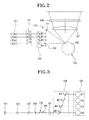
- Figures 2 and 3 are a plan view and a side view, respectively, of the internal structure of an embodiment of an image-forming apparatus according to the present invention;
- Figure 4 shows the transmittance characteristics of the second, third and fourth dichroic mirrors of the image-forming apparatus of Figure 3; and
- Figure 5 shows the reflection and transmission characteristics desirable for an optical member, such as a dichroic mirror, in an embodiment of the present invention.
-
- Referring to Figures 2 and 3, an image-forming apparatus (or light scanning device), according to the present invention, includes a
light source portion 101 having first, second, third and fourth laser diodes L1, L2, L3, L4, acollimator lens portion 102 having first, second, third and fourth collimator lenses C1, C2, C3, C4, a firstoptical output portion 103 having first, second, third and fourth dichroic mirrors M1-1, M1-2, M1-3, M1-4, acylinder lens 104, ascanning unit 105 including a polygonal reflectingmirror 106, an image-forminglens 107, a secondoptical output portion 108 including fifth, sixth, seventh and eighth dichroic mirrors M2-1, M2-2, M2-3, M2-4, synchronization system beam sensors (or synchronisation detection unit) 110, and a thirdoptical member 111. - The first to fourth diodes L1, L2, L3, L4 of the
light source portion 101 are disposed parallel to each other in a row. - The first to fourth collimator lenses C1, C2, C3, C4 are disposed in a row corresponding to respective laser diodes L1, L2, L3, L4 so as to collimate the laser beams emitted from each laser diode L1, L2, L3, L4.
- The first to fourth dichroic mirrors M1-1, M1-2, M1-3, M1-4 of the first
optical output portion 103 are disposed to reflect or transmit the light, which is transmitted through each of the collimator lenses C1, C2, C3, C4 and input to each respective dichroic mirror, and form a single output path at its end-most portion. As shown in Figure 2, each of the first to fourth dichroic mirrors M1-1, M1-2, M1-3, M1-4 is inclined such that the respective laser beams incident on the first to third dichroic mirrors M1-2, M1-2, M1-3 are each reflected at a right angle. The first to fourth dichroic mirrors M1-1, M1-2, M1-3, M1-4 are entirely disposed in a row. However, the first to fourth laser diodes L1, L2, L3, L4 and the first to fourth collimator lenses C1, C2, C3, C4 need not be disposed in a row, and may be disposed at different distances from the firstoptical output portion 103 in accordance with the respective wavelengths of the laser beams. Furthermore, although the first to fourth dichroic mirrors M1-1, M1-2, M1-3, M1-4 are vertically disposed, this should not be considered as limiting. For example, these elements may be inclined so that the incident light can be reflected at a desired constant angle. In addition, all of the first to fourth dichroic mirrors M1-1, M1-2, M1-3, M1-4 need not be dichroic mirrors. For example, in the case of the first dichroic mirror M1-1, a conventional reflecting mirror may be used. - The
cylinder lens 104 focuses the light output from the firstoptical output portion 103 on apolygonal mirror 106 of thescanning unit 105. - The
scanning unit 105 includes a motor (not shown) and thepolygonal mirror 106, and reflects the light transmitted through thecylinder lens 104 at a predetermined angle. - The image-forming
lens 107 transmits the light reflected by thescanning unit 105 to the secondoptical output portion 108. - The second
optical output portion 108 receives the light transmitted through the image-forminglens 107 at its front-most portion, and reflects or transmits the light at the fifth to eighth dichroic mirrors M2-1, M1-2, M1-3, M2-4 in accordance with the wavelength of the light, such that the light is scanned to corresponding photoreceptor (or photosensitive) drums D1, D2, D3, D4. - The second
optical output portion 108 receives a plurality of beams of different wavelengths along a common input path and outputs the beams along separate output paths in accordance with wavelength, i.e. it demultiplexes the beams. In contrast, the firstoptical output portion 103 receives a plurality of beams of different wavelengths along separate input paths and then outputs the beams along a common output path, i.e. it multiplexes the beams. However, both the first and secondoptical output portions optical output portion 108 will be omitted. - In the image-forming apparatus described above, the light, which is emitted from the first to fourth laser diodes L1, L2, L3, L4 of the
light source portion 101 in accordance with an image to be printed, is collimated by corresponding collimator lenses C1, C2, C3, C4 of thecollimator lens portion 102, and is then incident on the corresponding first to fourth dichroic mirrors M1-1, M1-2, M1-3, M1-4. The laser beams output from the laser diodes L1, L2, L3, L4 of thelight source portion 101 have different wavelengths, respectively. For example, the first laser diode L1 emits light having a wavelength of 650nm, and the second, third and fourth laser diodes emit laser beams having wavelengths of 780nm, 850nm and 950nm, respectively. - When the laser beams of different wavelengths are incident on the first
optical output portion 103, the first to fourth dichroic mirrors M1-1, M1-2, M1-3, M1-4 selectively reflect or transmit the laser beams and then output the laser beams from the end-most portion along a single output path to thescanning unit 105. More specifically, the fourth dichroic mirror M1-4 transmits the light which is output from the fourth collimator lens C4, whereas the first to third dichroic mirrors M1-1, M1-2, M1-3 reflect the light, which is output from the first to third collimator lenses C1, C2, C3 repectively, in a vertical direction. The second to fourth dichroic mirrors M1-2, M1-3, M1-4 selectively reflect or transmit the laser beams reflected from the first to third dichroic mirrors M1-1, M1-2, M1-3 according to the wavelength of the laser beams, and then these laser beams are reflected by the fourth dichroic mirror M1-4 to thescanning unit 105. - Referring to Figure 5, λ is the wavelength at the boundary between the transmission region and the reflection region of an optical member, such as a dichroic mirror of the first or second
optical output portions - Referring to Figure 4, on the basis of the above-described optical characteristics of the optical member, reflection and transmission characteristics of the first to fourth dichroic mirrors M1-1, M1-2, M1-3, M1-4 will be described. The first dichroic mirror M1-1 is a conventional reflecting mirror, to reflect the light emitted from the first to fourth laser diodes L1, L2, L3, L4. The second dichroic mirror M1-2 transmits the light emitted from the first laser diode L1 but reflects the light emitted from the second to fourth laser diodes L2, L3, L4. The third dichroic mirror M1-3 transmits the light emitted from the first and second laser diodes L1, L2 but reflects the light emitted from the third and fourth laser diodes L3, L4. The fourth dichroic mirror M1-4 reflects the light emitted from the first to third laser diodes L1, L2, L3 but transmits the light emitted from the fourth laser diode L4.
- Due to the characteristics described above, the light emitted from the first laser diode L1 is reflected from a surface of the first dichroic mirror M1-1, transmitted through the second and third dichroic mirrors M1-2, M1-3 and reflected by the fourth dichroic mirror M1-4 to the
cylinder lens 104. The light emitted from the second laser diode L2 is reflected by a surface of the second dichroic mirror M1-2, transmitted through the third dichroic mirror M1-3 and reflected by the fourth dichroic mirror M1-4 to thecylinder lens 104. The light emitted from the third laser diode L3 is reflected by the third dichroic mirror M1-3 and reflected again by the fourth dichroic mirror M1-4 to thecylinder lens 104. The light emitted from the fourth laser diode L4 is transmitted through the fourth dichroic mirror M1-4 to thecylinder lens 104. That is, since the laser beams which are incident on thecylinder lens 104 have the same output path regardless of their wavelength, in the region of the light path from thecylinder lens 104 to the image-forminglens 107, the image-forming apparatus resembles a mono laser beam printer using a single laser diode. - The combined laser beam, which comprises the plurality of wavelength components is transmitted through the image-forming
lens 107, and is selectively reflected by or transmitted through the fifth to eighth dichroic mirrors M2-1, M2-2, M2-3, M2-4 of the secondoptical output portion 108, before being output to corresponding photoreceptor drums D1, D2, D3, D4. In this embodiment, the arrangement of each of the dichroic mirrors M2-1, M2-2, M2-3, M2-4 of the secondoptical output portion 108 is applied in the same way as that of each dichroic mirror M1-1, M1-2, M1-3, M1-4 of the firstoptical output portion 103. In other words, the laser beam emitted from the fourth laser diode L4 is transmitted through the eighth dichroic mirror M2-4 and is then output to the fourth photoreceptor drum D4. The laser beam emitted from the third laser diode L3 is reflected by the eighth dichroic mirror M2-4, reflected again by the seventh dichroic mirror M2-3 and is then output to the third photoreceptor drum D3. The light emitted from the second dichroic mirror L2 is reflected by the eighth dichroic mirror M2-4, transmitted through the seventh dichroic mirror M2-3, reflected again by the sixth dichroic mirror M2-2 and then output to the second photoreceptor drum D2. The light emitted from the first laser diode L1 is reflected by the eighth dichroic mirror M2- 4, transmitted through the sixth and seventh dichroic mirrors M2-3, M2-2 in turn, reflected again by the fifth dichroic mirror M2-1 and then output to the first photoreceptor drum D1. - In order to control the horizontal synchronization of the scanning line scanned across each photoreceptor drum D1, D2, D3, D4, the synchronization
system beam sensors 110 detect a laser beam reflected at a desired position of thescanning unit 105 and then send a signal to a control unit (not shown) of the system. At this time, the thirdoptical member 111 for selectively reflecting or transmitting the laser beam may be disposed or omitted on the light path along which the light is incident to the synchronizationsystem beam sensors 110. Since the synchronizationsystem beam sensors 110 detect a laser beam which is equivalent to that which is scanned to each photoreceptor drum D1, D2, D3, D4, it is possible to synchronize the four scanning lines using only one set of synchronizationsystem beam sensors 110 without the need for separate synchronization system beams sensors for each photoreceptor drum D1, D2, D3, D4. - In the tandem type image-forming apparatus described above, by using the arrangement of a light source emitting light beams with different wavelengths and optical members having various reflection and transmission regions corresponding to the wavelengths of the light beams, the light beams are transmitted along a single output path to the
scanning unit 105. The light corresponding to each colour signal is output from thescanning unit 105 along a single path, and then scanned through the optical members onto a different photoreceptor drum corresponding to each colour signal. Thus an image-forming apparatus having a simple structure and a small size is provided. - Furthermore, since it is possible to control the horizontal synchronization of the light scanned across each photoreceptor drum using only one set of synchronization system beam sensors, separate compensating units are not needed to compensate for the bow of the scanning line according to the synchronization detection adjusting unit or the image data. Therefore, fabrication costs are reduced.
Claims (19)
- A multi-colour image-forming apparatus comprising a plurality of light sources (L1, L2, L3, L4) for emitting a plurality of beams and a plurality of photoreceptors (D1, D2, D3, D4) for receiving respective beams, characterised in that the beams are wavelength division multiplexed between the light sources (L1, L2, L3, L4) and the photoreceptors (D1, D2, D3, D4).
- An apparatus according to claim 1, comprising an optical multiplexer (103) for multiplexing the beams at the beginning of a common path, and an optical demultiplexer (108) for demultiplexing the beams at the end of the common path.
- An apparatus according to claim 2, wherein the optical multiplexer (103) comprises a plurality of dichroic mirrors (M1-1, M1-2, M1-3, M1-4) disposed in a row.
- An apparatus according to claim 2, wherein the optical demultiplexer (108) comprises a plurality of dichroic mirrors (M2-1, M2-2, M2-3, M2-4) disposed in a row.
- An apparatus according to claim 2, comprising scanning means (105) for scanning the beams across the respective photoreceptors (D1, D2, D3, D4), said scanning means (105) being disposed in the common path.
- An apparatus according to claim 5, wherein the scanning means (105) comprises a polygonal mirror (106).
- An apparatus according to claim 5 or 6, comprising synchronisation system beam sensors (110) for detecting a wavelength division multiplexed beam received from the scanning means (105).
- An apparatus according to any preceding claim, wherein the light sources (L1, L2, L3, L4) are laser diodes.
- A light scanning device, comprising:a plurality of laser beam sources disposed to be parallel with each other, to emit laser beams having various wavelengths according to image data;a plurality of photosensitive drums corresponding to the plurality of laser beam sources;a plurality of collimator lenses to transform the laser beams emitted from the laser beam sources into parallel light;a first optical output portion having a plurality of first optical members to reflect or transmit the parallel light through a first surface thereof, and reflect or transmit the reflected light through a second surface thereof according to the wavelengths, and thus output the laser beams of the various wavelengths along a single output path at an output portion thereof;a scanning unit to reflect the light output from the first optical output portion; anda second optical output portion having a plurality of second optical members disposed in a row so as to receive the light reflected from the scanning unit at an input portion thereof and selectively reflect or transmit the received light according to the wavelengths, and scan the reflected/transmitted light to the corresponding photosensitive drums.
- The device of claim 9, further comprising a focusing lens to focus the light output from the first optical output portion on a reflecting surface of the scanning unit.
- The device of claim 10, further comprising an image forming lens to focus the light reflected by the scanning unit on the second optical member closest to the input portion thereof.
- The device of claim 11, further comprising a synchronization detecting unit to detect a synchronization signal and control a horizontal synchronization of an image formed by the light reflected by the scanning unit.
- The device of claim 12, further comprising a third optical member to selectively transmit or reflect the light which is incident to the synchronization detecting unit.
- The device of claim 9, wherein the first and second optical members respectively have different reflection and transmission regions according to the wavelength of the incident light.
- The device of claim 14, wherein the first optical members are disposed in a row
- The device of claim 15, wherein the first optical members are disposed perpendicular to an incident direction of the light.
- The device of claim 9, wherein the first and second optical members are dichroic mirrors.
- The device of claim 9, wherein the first and second optical members are transparent glasses on which dichroic is coated.
- The device of claim 9, wherein the first and second optical members are band pass filters.
Applications Claiming Priority (2)
| Application Number | Priority Date | Filing Date | Title |
|---|---|---|---|
| KR10-2002-0057243A KR100433432B1 (en) | 2002-09-19 | 2002-09-19 | Scanning unit of laser printer |
| KR2002057243 | 2002-09-19 |
Publications (3)
| Publication Number | Publication Date |
|---|---|
| EP1400361A2 true EP1400361A2 (en) | 2004-03-24 |
| EP1400361A3 EP1400361A3 (en) | 2004-07-14 |
| EP1400361B1 EP1400361B1 (en) | 2006-03-29 |
Family
ID=36274100
Family Applications (1)
| Application Number | Title | Priority Date | Filing Date |
|---|---|---|---|
| EP03254708A Expired - Lifetime EP1400361B1 (en) | 2002-09-19 | 2003-07-28 | Multi-colour image-forming apparatus |
Country Status (5)
| Country | Link |
|---|---|
| US (1) | US20040056185A1 (en) |
| EP (1) | EP1400361B1 (en) |
| KR (1) | KR100433432B1 (en) |
| CN (1) | CN1484109A (en) |
| DE (1) | DE60304295T2 (en) |
Cited By (1)
| Publication number | Priority date | Publication date | Assignee | Title |
|---|---|---|---|---|
| RU2392648C1 (en) * | 2007-10-16 | 2010-06-20 | Кэнон Кабусики Кайся | Optical scanning device and image formation device using such analyser |
Families Citing this family (4)
| Publication number | Priority date | Publication date | Assignee | Title |
|---|---|---|---|---|
| KR100813960B1 (en) * | 2005-05-27 | 2008-03-14 | 삼성전자주식회사 | Scanning optics and image forming apparatus employing the same |
| JP4682948B2 (en) | 2006-07-27 | 2011-05-11 | 富士ゼロックス株式会社 | Optical scanning apparatus and image forming apparatus |
| DE102012107040A1 (en) * | 2012-08-01 | 2014-05-28 | Jenoptik Optical Systems Gmbh | Achromatic scanning device with monochromatic f-theta lens |
| JP6846238B2 (en) * | 2017-03-07 | 2021-03-24 | 東京エレクトロン株式会社 | Droplet ejection device, droplet ejection method, program and computer storage medium |
Citations (1)
| Publication number | Priority date | Publication date | Assignee | Title |
|---|---|---|---|---|
| KR20000047538A (en) | 1998-12-18 | 2000-07-25 | 사까모도 마사모도 | Optical scanning device |
Family Cites Families (12)
| Publication number | Priority date | Publication date | Assignee | Title |
|---|---|---|---|---|
| JPS5918965A (en) * | 1982-07-23 | 1984-01-31 | Fuji Xerox Co Ltd | Exposure quantity detecting device of copying machine |
| US5012259A (en) * | 1988-01-28 | 1991-04-30 | Konica Corporation | Color recorder with gas laser beam scanning |
| US5068677A (en) * | 1988-09-20 | 1991-11-26 | Minolta Camera Kabushiki Kaisha | Laser scanner with selected plural beam sources |
| JPH0283518A (en) * | 1988-09-20 | 1990-03-23 | Minolta Camera Co Ltd | Laser beam scanner |
| JP2778986B2 (en) * | 1989-05-26 | 1998-07-23 | 富士写真フイルム株式会社 | Image recording device |
| JP2881923B2 (en) * | 1990-03-08 | 1999-04-12 | ブラザー工業株式会社 | Printing device and color printer |
| JP2995925B2 (en) * | 1991-06-14 | 1999-12-27 | ミノルタ株式会社 | Laser beam synthesis method |
| US5341158A (en) * | 1992-09-22 | 1994-08-23 | Xerox Corporation | Raster output scanner for a xerographic printing system having laser diodes arranged in a line parallel to the fast scan direction |
| US5668590A (en) * | 1993-06-24 | 1997-09-16 | Hitachi, Ltd. | Optical beam scanning system with rotating beam compensation |
| IL107508A (en) * | 1993-11-05 | 1996-12-05 | Orbotech Ltd | Method and apparatus for recording on optically-sensitive media |
| US5666447A (en) * | 1994-11-21 | 1997-09-09 | Eastman Kodak Company | Using optical fiber multiplexer to combine light beams in a laser printer |
| JPH10149430A (en) * | 1996-11-20 | 1998-06-02 | Brother Ind Ltd | Collimator lens, optical scanning device, optical information reading device, optical information recording device, and copying device |
-
2002
- 2002-09-19 KR KR10-2002-0057243A patent/KR100433432B1/en not_active Expired - Fee Related
-
2003
- 2003-05-14 US US10/436,998 patent/US20040056185A1/en not_active Abandoned
- 2003-07-01 CN CNA03147103XA patent/CN1484109A/en active Pending
- 2003-07-28 DE DE60304295T patent/DE60304295T2/en not_active Expired - Fee Related
- 2003-07-28 EP EP03254708A patent/EP1400361B1/en not_active Expired - Lifetime
Patent Citations (1)
| Publication number | Priority date | Publication date | Assignee | Title |
|---|---|---|---|---|
| KR20000047538A (en) | 1998-12-18 | 2000-07-25 | 사까모도 마사모도 | Optical scanning device |
Cited By (1)
| Publication number | Priority date | Publication date | Assignee | Title |
|---|---|---|---|---|
| RU2392648C1 (en) * | 2007-10-16 | 2010-06-20 | Кэнон Кабусики Кайся | Optical scanning device and image formation device using such analyser |
Also Published As
| Publication number | Publication date |
|---|---|
| DE60304295T2 (en) | 2007-01-25 |
| KR20040025320A (en) | 2004-03-24 |
| US20040056185A1 (en) | 2004-03-25 |
| KR100433432B1 (en) | 2004-05-31 |
| EP1400361B1 (en) | 2006-03-29 |
| EP1400361A3 (en) | 2004-07-14 |
| DE60304295D1 (en) | 2006-05-18 |
| CN1484109A (en) | 2004-03-24 |
Similar Documents
| Publication | Publication Date | Title |
|---|---|---|
| US20050099663A1 (en) | Optical scanner and image forming apparatus | |
| TW580448B (en) | Color laser printer | |
| US5179462A (en) | Laser beam composite apparatus | |
| KR100795147B1 (en) | Image forming apparatus | |
| EP1400361B1 (en) | Multi-colour image-forming apparatus | |
| EP2360508B1 (en) | Multiple-source multiple-beam polarized laser scanning system | |
| US7151624B2 (en) | Light scanning unit | |
| JP4632821B2 (en) | Multi-beam optical scanning device and image forming apparatus | |
| JP5115351B2 (en) | Tandem scanning optical system | |
| JP2005055872A (en) | Laser scanning unit and image forming apparatus | |
| JP5364969B2 (en) | Optical scanning device | |
| US20240201483A1 (en) | Optical scanning device and image forming apparatus | |
| US6954312B2 (en) | Light scanning unit | |
| JP5364970B2 (en) | Optical scanning device | |
| JP2004301974A (en) | Scanning optical device | |
| JP2006258983A (en) | Optical scanner | |
| JP2001343603A (en) | Multi-beam light source scanning device | |
| JP2004309634A (en) | Optical scanning device | |
| JP2006323278A (en) | Optical scanner | |
| JP2002277781A (en) | Multiple beam raster output scanning system | |
| CN100487517C (en) | Laser scanning unit and tandem image forming apparatus having the same | |
| EP0781663B1 (en) | Color xerographic printer with multiple linear arrays of surface emitting lasers with dissimilar wavelengths | |
| JPH10186252A (en) | Optical scanner and image forming device | |
| JP2010262245A (en) | Optical scanner | |
| JP2003270570A (en) | Multibeam scanning optical system |
Legal Events
| Date | Code | Title | Description |
|---|---|---|---|
| PUAI | Public reference made under article 153(3) epc to a published international application that has entered the european phase |
Free format text: ORIGINAL CODE: 0009012 |
|
| AK | Designated contracting states |
Kind code of ref document: A2 Designated state(s): AT BE BG CH CY CZ DE DK EE ES FI FR GB GR HU IE IT LI LU MC NL PT RO SE SI SK TR |
|
| AX | Request for extension of the european patent |
Extension state: AL LT LV MK |
|
| PUAL | Search report despatched |
Free format text: ORIGINAL CODE: 0009013 |
|
| AK | Designated contracting states |
Kind code of ref document: A3 Designated state(s): AT BE BG CH CY CZ DE DK EE ES FI FR GB GR HU IE IT LI LU MC NL PT RO SE SI SK TR |
|
| AX | Request for extension of the european patent |
Extension state: AL LT LV MK |
|
| 17P | Request for examination filed |
Effective date: 20040730 |
|
| RAP1 | Party data changed (applicant data changed or rights of an application transferred) |
Owner name: SAMSUNG ELECTRONICS CO., LTD. |
|
| GRAP | Despatch of communication of intention to grant a patent |
Free format text: ORIGINAL CODE: EPIDOSNIGR1 |
|
| AKX | Designation fees paid |
Designated state(s): DE FR GB NL |
|
| GRAS | Grant fee paid |
Free format text: ORIGINAL CODE: EPIDOSNIGR3 |
|
| GRAA | (expected) grant |
Free format text: ORIGINAL CODE: 0009210 |
|
| AK | Designated contracting states |
Kind code of ref document: B1 Designated state(s): DE FR GB NL |
|
| REG | Reference to a national code |
Ref country code: GB Ref legal event code: FG4D |
|
| PGFP | Annual fee paid to national office [announced via postgrant information from national office to epo] |
Ref country code: FR Payment date: 20060517 Year of fee payment: 4 |
|
| REF | Corresponds to: |
Ref document number: 60304295 Country of ref document: DE Date of ref document: 20060518 Kind code of ref document: P |
|
| PGFP | Annual fee paid to national office [announced via postgrant information from national office to epo] |
Ref country code: DE Payment date: 20060728 Year of fee payment: 4 |
|
| ET | Fr: translation filed | ||
| PLBE | No opposition filed within time limit |
Free format text: ORIGINAL CODE: 0009261 |
|
| STAA | Information on the status of an ep patent application or granted ep patent |
Free format text: STATUS: NO OPPOSITION FILED WITHIN TIME LIMIT |
|
| 26N | No opposition filed |
Effective date: 20070102 |
|
| GBPC | Gb: european patent ceased through non-payment of renewal fee |
Effective date: 20070728 |
|
| NLV4 | Nl: lapsed or anulled due to non-payment of the annual fee |
Effective date: 20080201 |
|
| PG25 | Lapsed in a contracting state [announced via postgrant information from national office to epo] |
Ref country code: NL Free format text: LAPSE BECAUSE OF NON-PAYMENT OF DUE FEES Effective date: 20080201 Ref country code: DE Free format text: LAPSE BECAUSE OF NON-PAYMENT OF DUE FEES Effective date: 20080201 |
|
| PG25 | Lapsed in a contracting state [announced via postgrant information from national office to epo] |
Ref country code: GB Free format text: LAPSE BECAUSE OF NON-PAYMENT OF DUE FEES Effective date: 20070728 |
|
| REG | Reference to a national code |
Ref country code: FR Ref legal event code: ST Effective date: 20080331 |
|
| PG25 | Lapsed in a contracting state [announced via postgrant information from national office to epo] |
Ref country code: FR Free format text: LAPSE BECAUSE OF NON-PAYMENT OF DUE FEES Effective date: 20070731 |