EP1400341B1 - Co-cured vacuum-assisted resin transfer molding manufacturing method - Google Patents
Co-cured vacuum-assisted resin transfer molding manufacturing method Download PDFInfo
- Publication number
- EP1400341B1 EP1400341B1 EP03255455A EP03255455A EP1400341B1 EP 1400341 B1 EP1400341 B1 EP 1400341B1 EP 03255455 A EP03255455 A EP 03255455A EP 03255455 A EP03255455 A EP 03255455A EP 1400341 B1 EP1400341 B1 EP 1400341B1
- Authority
- EP
- European Patent Office
- Prior art keywords
- preforms
- skin panel
- prepreg skin
- vacuum
- resin
- Prior art date
- Legal status (The legal status is an assumption and is not a legal conclusion. Google has not performed a legal analysis and makes no representation as to the accuracy of the status listed.)
- Expired - Lifetime
Links
- 229920005989 resin Polymers 0.000 title claims abstract description 62
- 239000011347 resin Substances 0.000 title claims abstract description 62
- 238000004519 manufacturing process Methods 0.000 title claims abstract description 12
- 238000001721 transfer moulding Methods 0.000 title claims abstract description 12
- 238000000034 method Methods 0.000 claims abstract description 36
- 230000035699 permeability Effects 0.000 claims abstract description 21
- 239000004744 fabric Substances 0.000 claims description 12
- 239000000835 fiber Substances 0.000 claims description 8
- 238000001802 infusion Methods 0.000 claims description 8
- 238000010438 heat treatment Methods 0.000 claims description 6
- 239000000853 adhesive Substances 0.000 claims description 4
- 230000001070 adhesive effect Effects 0.000 claims description 4
- 230000008878 coupling Effects 0.000 claims 4
- 238000010168 coupling process Methods 0.000 claims 4
- 238000005859 coupling reaction Methods 0.000 claims 4
- 238000011417 postcuring Methods 0.000 claims 2
- 238000009849 vacuum degassing Methods 0.000 claims 2
- 239000002131 composite material Substances 0.000 description 34
- 230000008901 benefit Effects 0.000 description 7
- 239000000463 material Substances 0.000 description 7
- 230000008569 process Effects 0.000 description 7
- 239000002313 adhesive film Substances 0.000 description 3
- XQUPVDVFXZDTLT-UHFFFAOYSA-N 1-[4-[[4-(2,5-dioxopyrrol-1-yl)phenyl]methyl]phenyl]pyrrole-2,5-dione Chemical compound O=C1C=CC(=O)N1C(C=C1)=CC=C1CC1=CC=C(N2C(C=CC2=O)=O)C=C1 XQUPVDVFXZDTLT-UHFFFAOYSA-N 0.000 description 2
- 229920003192 poly(bis maleimide) Polymers 0.000 description 2
- 230000009467 reduction Effects 0.000 description 2
- 239000004593 Epoxy Substances 0.000 description 1
- 239000004809 Teflon Substances 0.000 description 1
- 229920006362 Teflon® Polymers 0.000 description 1
- 238000007792 addition Methods 0.000 description 1
- 230000004075 alteration Effects 0.000 description 1
- 239000011230 binding agent Substances 0.000 description 1
- 238000005056 compaction Methods 0.000 description 1
- 230000000295 complement effect Effects 0.000 description 1
- 238000010276 construction Methods 0.000 description 1
- 230000008030 elimination Effects 0.000 description 1
- 238000003379 elimination reaction Methods 0.000 description 1
- 239000002657 fibrous material Substances 0.000 description 1
- 238000002347 injection Methods 0.000 description 1
- 239000007924 injection Substances 0.000 description 1
- 230000010354 integration Effects 0.000 description 1
- 239000000203 mixture Substances 0.000 description 1
- 238000009745 resin transfer moulding Methods 0.000 description 1
- 239000003351 stiffener Substances 0.000 description 1
- 239000004753 textile Substances 0.000 description 1
- 239000013585 weight reducing agent Substances 0.000 description 1
Images


Classifications
-
- B—PERFORMING OPERATIONS; TRANSPORTING
- B29—WORKING OF PLASTICS; WORKING OF SUBSTANCES IN A PLASTIC STATE IN GENERAL
- B29C—SHAPING OR JOINING OF PLASTICS; SHAPING OF MATERIAL IN A PLASTIC STATE, NOT OTHERWISE PROVIDED FOR; AFTER-TREATMENT OF THE SHAPED PRODUCTS, e.g. REPAIRING
- B29C70/00—Shaping composites, i.e. plastics material comprising reinforcements, fillers or preformed parts, e.g. inserts
- B29C70/04—Shaping composites, i.e. plastics material comprising reinforcements, fillers or preformed parts, e.g. inserts comprising reinforcements only, e.g. self-reinforcing plastics
- B29C70/28—Shaping operations therefor
- B29C70/40—Shaping or impregnating by compression not applied
- B29C70/42—Shaping or impregnating by compression not applied for producing articles of definite length, i.e. discrete articles
- B29C70/44—Shaping or impregnating by compression not applied for producing articles of definite length, i.e. discrete articles using isostatic pressure, e.g. pressure difference-moulding, vacuum bag-moulding, autoclave-moulding or expanding rubber-moulding
- B29C70/443—Shaping or impregnating by compression not applied for producing articles of definite length, i.e. discrete articles using isostatic pressure, e.g. pressure difference-moulding, vacuum bag-moulding, autoclave-moulding or expanding rubber-moulding and impregnating by vacuum or injection
-
- B—PERFORMING OPERATIONS; TRANSPORTING
- B29—WORKING OF PLASTICS; WORKING OF SUBSTANCES IN A PLASTIC STATE IN GENERAL
- B29D—PRODUCING PARTICULAR ARTICLES FROM PLASTICS OR FROM SUBSTANCES IN A PLASTIC STATE
- B29D99/00—Subject matter not provided for in other groups of this subclass
- B29D99/001—Producing wall or panel-like structures, e.g. for hulls, fuselages, or buildings
- B29D99/0014—Producing wall or panel-like structures, e.g. for hulls, fuselages, or buildings provided with ridges or ribs, e.g. joined ribs
Definitions
- the present invention relates generally to the field of composites construction and, more particularly, to a co-cured resin vacuum-assisted transfer molding manufacturing method.
- Composite structures are desirable in many industries for many applications. For example, aircraft, space, and land/sea vehicles employ a variety of curved and multiple-contoured surface structures in their fabrication. Composite materials are commonly used for these structures because, among other desirable attributes, composite materials have high strength-to-weight ratios and allow the design and fabrication of large integrated composite structures. Even so, structures formed from composite materials oftentimes need to be stiffened or joined to adjacent structures. Therefore, manufacturers of composite structures are continually searching for better and more economical ways of stiffening and/or assembling composite structures.
- a co-cured vacuum-assisted resin transfer molding manufacturing method includes providing a tool base, disposing a prepreg skin panel outwardly from the tool base, disposing one or more tooling details outwardly from the prepreg skin panel, and disposing one or more preforms proximate the one or more tooling details.
- the one or more preforms are either dry or binderized.
- the method further includes disposing a high permeability medium between the one or more tooling details and the one or more preforms enclosing the prepreg skin panel, the one or more tooling details, the one or more preforms, and the high permeability medium with at least one vacuum bag, pulling a vacuum on the vacuum bag, infusing the one or more preforms with a resin, and curing the one or more ppreforms and the prepreg skin panel.
- Embodiments of the invention provide a number of technical advantages. Embodiments of the invention may include all, some, or none of these advantages.
- a composite structure manufactured according to one embodiment of the present invention is cost-efficient because of the substantial reduction or elimination of touch labor allowed by part count and fastener count reduction due to part integration.
- superior dimensional control and less weight of stiffened composite structure is achieved. This weight reduction is particularly advantageous in aircaraft applications.
- a manufacturer of composite structures may tailor a skin panel for weight efficiency and high performance via unidirectional prepreg product forms, for example. Also, three-dimensional preform substructure joints improve joint producibility and structural performance.
- large scale integrated structures may be fabricated out-of-autoclave, which saves time and cost.
- no mechanical fasteners or adhesives are needed to attach a substructure to a skin panel, which saves considerable time and money in constructing stiffened composite structures.
- Z-pins or film adhesives may be used to complement the co-curing of the substructure to the skin panel to improve crack propagation resistance.
- EP-A-722 026 discloses a manufacturing technique combining the use of prepregs and resin transfer moulding, resulting in panel-like structures.
- FIGURES 1 through 3D of the drawings in which like numerals refer to like parts.
- FIGURE 1 is a perspective view of an aircraft 100 having a panel 102 formed from a composite structure 200 (FIGURE 2) constructed according to one embodiment of the present invention.
- Aircraft 100 may be any suitable aircraft and panel 102 may be any suitable structural panel on aircraft 100, such as a tail panel, a wing panel, or a fuselage panel.
- panel 102 may be employed in any suitable aircraft, space, land/sea vehicle, or other machines, devices, or structures formed by composite materials.
- the following detailed description uses an aircraft application to illustrate one or more embodiments of composite structure 200 manufactured according to the teachings of the present invention.
- One embodiment of composite structure 200 is illustrated below in conjunction with FIGURE 2.
- FIGURE 2 is an inside perspective view of one embodiment of composite structure 200.
- Composite structure 200 is formed from, in one embodiment, a prepreg skin panel 202 and one or more preforms 204 that are cocured to prepreg skin panel 202 according to the teachings of the present invention as set forth below.
- a "prepreg” is a composite material (i.e., fiber that is impregnated with a resin) that is not yet cured, though may be partially staged.
- Prepreg skin panel 202 is formed from a composite material having any suitable fibers impregnated with any suitable resin. Accordingly, the fibers in prepreg skin panel 202 may be formed from any suitable 2D and/or 3D material and may be uni-directional, bi-directional, chopped, woven or braided. Any suitable number of layers of fiber may be used to form prepreg skin panel 202.
- the resin may be any suitable resin, such as epoxy or bismaleimide.
- Prepreg skin panel 202 may be formed using any suitable composite forming technique, such as hand laid, tape laid, fiber placed, or may be a hybrid skin panel. In the illustrated embodiment, prepreg skin panel 202 forms a portion of an outer skin of aircraft 100.
- prepreg skin panel 202 may coincide with a portion of the outer skin of a tail section, a wing section, or a fuselage section, as mentioned above. Accordingly, prepreg skin panel 202 may have any suitable shape, dimensions, and thickness. In addition, prepreg skin panel 202 may be substantially flat or may have one or more contours to conform to the shape of a particular portion of aircraft 100 or other suitable vehicle or device.
- Preforms 204 function to impart strength and/or stiffness to prepreg skin panel 202 or serve as attachment members.
- preforms 204 are typically in the form of structural shapes, such as I-beams, T-beams, hat stiffeners, or other suitable structural shapes.
- preforms 204 form a number of ribs and spars for panel 102 of aircraft 100.
- preforms 204 may be arranged in any suitable configuration depending on the design parameters for composite structure 200.
- Preforms 204 are either dry or binderized, and may be any suitable textile preform, such as a fabric preform, a stitched preform, a warp knit preform, a 3D preform, a braided preform, or any combination thereof.
- the fiber material may be the same as, or different from, the fiber used in prepreg skin panel 202.
- Binderized preforms are preforms with resin applied to the surface(s) to provide tack and handling stability to the preform. Any suitable binder resin may be utilized that is compatible with design requirements and manufacturing process.
- preforms 204 are joined to prepreg skin panel 202 via co-curing of prepreg skin panel 202 with resin-infused preforms 204, as described in detail below in conjunction with FIGURES 3A through 3D.
- This co-curing forms a unitized/integrated structure that blends the strengths of many different product forms and processes into a cost-efficient, performance-driven composite structure 200.
- some embodiments of the present invention capitalize on the dimensional precision of vacuum-assisted resin transfer molding type tooling and the high tailorability, performance, and weight efficiency of prepreg product forms.
- An important technical advantage of the present invention is that very large structures, such as skin panels for aircraft 100, may be integrated to very large preforms for stiffening and/or attachment purposes.
- FIGURES 3A through 3D are perspective views demonstrating one method of constructing composite structure 200 according to one embodiment of the present invention.
- the method begins by disposing prepreg skin panel 202 outwardly from a tool base 304 of a tool 300.
- Tool base 304 which is formed from any suitable material, may have any suitable configuration depending on the configuration of prepreg skin panel 202 and preforms 204.
- prepreg skin panel 202 may be vacuum debulked, which may remove some of the air pockets in prepreg skin panel 202.
- the vacuum debulking of prepreg skin panel 202 may be performed at room temperature.
- An additional vacuum debulk cycle at an elevated temperature for a predetermined time may optionally be utilized.
- prepreg skin panel 202 may be vacuum debulked at room temperature during lay-up and, after skin collation, debulked at an elevated temperature to improve compaction, such as 250° F ⁇ 50° F, for 30-120 minutes.
- Pressure may also optionally be applied to further compact prepreg skin panel 202 during debulking. Staging may optionally be utilized to modify the cure characteristics or flow of the prepreg resin.
- the next step in the illustrated method is to build up preforms 204 into a predetermined configuration as defined by the design parameters.
- a predetermined configuration is illustrated by the ribs and spars (denoted by reference numerals 204) in FIGURE 2.
- a first tooling detail 302 is shown in FIGURE 3A to be disposed on a portion of prepreg skin panel 202.
- a tooling detail as described herein refers to a portion or component of an overall tool that is used as a mold for forming composite structure 200.
- Tooling detail 302 may be formed from any suitable material.
- preform 204 Disposed proximate tooling detail 302 is a preform 204.
- preform 204 includes web portions 306 and 307, which are proximate a side of tooling detail 302, and flange portions 308 and 309, portions of which are sandwiched between tooling detail 302 and prepreg skin panel 202.
- the material, dimensions and configuration of both web portions 306, 307 and flange portions 308, 309 are determined by the design of composite structure 200.
- tooling detail 302 may also include a high permeability medium 310, which may be disposed between tooling detail 302 and a portion of web portions 306, 307 and flange portions 308, 309.
- High permeability medium 310 may be any suitable material, such as a composite screen, that facilitates the flow of resin during a vacuum-assisted resin transfer molding process.
- High permeability medium 310 is disposed on an outer surface of tooling detail 302 in a position determined by design parameters of the vacuum-assisted resin transfer molding process, such as where the resin is infused and the configuration and details of preforms 204.
- release fabric 312 is disposed between high permeability medium 310 and both web portions 306, 307 and flange portions 308, 309. Release fabric 312 may also continue between tooling detail 302 and prepreg skin panel 202.
- Release fabric 312 may be any suitable release fabric, such as a Teflon coated release fabric. Release fabric 312 may be of any size larger than high permeability medium 310.
- a wrap ply may be utilized in some embodiments to facilitate prepreg skin panel 202 design intention. If utilized, the wrap ply is disposed between preform 204 and tooling detail 302. As another option, a resin film (not shown) may be used on the outer surface of the wrap ply and preform 204 to facilitate the placement of wrap ply and preform 204 onto tooling detail 302 and/or the wrap ply.
- the resin film is typically a tacky material that allows non-tacky materials to stay in place.
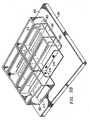
- Separate tooling details 302 are used to form separate portions of the overall configuration of preforms 204. Each tooling detail 302 is sequentially disposed on base plate 304 with their respective preforms 204 until all tooling details 302 have been placed. In the example illustrated in FIGURES 3A through 3D, a total of eight tooling details 302 are utilized; however, any suitable number of tooling details may be utilized depending on the configuration of composite structure 200.
- FIGURE 3B shows seven of those eight tooling details 302 placed on tool base 304 of tool 300.
- the general configuration of preforms 204 as outlined in FIGURE 2 above may be seen in hidden lines Because the final tooling detail 302 has not been placed on tool base 304 yet, one can see a preform denoted by reference numeral 316 that comprises a portion of a spar web, and a preform as denoted by reference numeral 318. that comprises a portion of a rib web.
- prepreg skin panel 202 and preforms 204 are ready to be co-cured via a vacuum-assisted resin transfer molding process, as described below in conjunction with FIGURE 3D.
- a plurality of fasteners 322, such as Z-pins may couple prepreg skin panel 202 to preforms 204 for added strength and/or damage resistance.
- fasteners 322 may inhibit crack propagation.
- Fasteners 322 may be inserted by any suitable process, such as pushing or driving while being vibrated with ultrasonic energy. Any suitable number of fasteners 322 may be utilized in any suitable configuration.
- An adhesive film may optionally be disposed between prepreg skin panel 202 and preforms 204.
- the adhesive film may provide additional bonding between prepreg skin panel 202 and preforms 204. Any suitable adhesive film may be utilized that is compatible with design requirements and manufacturing process.
- FIGURE 3D illustrates one embodiment of a vacuum-assisted resin transfer molding process for the co-curing of prepreg skin panel 202 and preforms 204.
- Any suitable vacuum bag forming process may be utilized, such as single or double vacuum bag forming.
- a vacuum source 319 is used to pull a vacuum on a vacuum bag 320.
- resin contained within a reservoir 322 is allowed to travel through an inlet line 323 into tool base 304 so that the resin may infuse preforms 204 within vacuum bag 320.
- the infusion is continued until the resin is "witnessed" in a witness line 324.
- Embodiments of the infusion and curing cycle is described as follows.
- Vacuum is applied to vacuum bag 320 and tool base 304 is heated to a predetermined temperature, such as 122°C ⁇ 10°C (250° Fahrenheit ⁇ 50° F). Other suitable temperatures may be utilized, such as room temperature.
- the heating of tool base 304 may be accomplished in an oven or tool base 304 may be a self-heated tool.
- the resin to be infused is heated in reservoir 322 to a predetermined temperature, such as 122°C ⁇ 10°C (250° Fahrenheit ⁇ 50° F). Again, other suitable temperatures may be utilized, such as room temperature.
- the resin is heated to a temperature which is less than the temperature of tool base 304. After heating the resin, the resin is vacuum degassed, which prepares the resin for infusion. The resin may also be vacuum degassed at room temperature. After the infusion of the resin (at either an elevated temperature or room temperature), the final curing cycle takes place.
- tool base 304 is heated from its injection temperature to a higher temperature, such as 149° - 204°C (300°-400° Fahrenheit). Tool base 304 is then held for a predetermined time, such as six hours. This holding period helps cure prepreg skin panel 202 and newly resin infused preforms 204 and join them together.
- a post cure may be performed for a predetermined time period. For example, a post cure may be carried out at 227°C (440° F) for approximately six hours for a bismaleimide resin.
- This curing may take place while composite structure 200 is in tool base 304 or composite structure 200 may be removed from tool base 304 and placed in any suitable oven. Other suitable temperatures and hold times may be utilized.
Landscapes
- Engineering & Computer Science (AREA)
- Mechanical Engineering (AREA)
- Chemical & Material Sciences (AREA)
- Composite Materials (AREA)
- Architecture (AREA)
- Civil Engineering (AREA)
- Structural Engineering (AREA)
- Casting Or Compression Moulding Of Plastics Or The Like (AREA)
- Moulding By Coating Moulds (AREA)
- Addition Polymer Or Copolymer, Post-Treatments, Or Chemical Modifications (AREA)
Abstract
Description
- The present invention relates generally to the field of composites construction and, more particularly, to a co-cured resin vacuum-assisted transfer molding manufacturing method.
- Composite structures are desirable in many industries for many applications. For example, aircraft, space, and land/sea vehicles employ a variety of curved and multiple-contoured surface structures in their fabrication. Composite materials are commonly used for these structures because, among other desirable attributes, composite materials have high strength-to-weight ratios and allow the design and fabrication of large integrated composite structures. Even so, structures formed from composite materials oftentimes need to be stiffened or joined to adjacent structures. Therefore, manufacturers of composite structures are continually searching for better and more economical ways of stiffening and/or assembling composite structures.
- According to one embodiment of the invention, a co-cured vacuum-assisted resin transfer molding manufacturing method includes providing a tool base, disposing a prepreg skin panel outwardly from the tool base, disposing one or more tooling details outwardly from the prepreg skin panel, and disposing one or more preforms proximate the one or more tooling details. The one or more preforms are either dry or binderized. The method further includes disposing a high permeability medium between the one or more tooling details and the one or more preforms enclosing the prepreg skin panel, the one or more tooling details, the one or more preforms, and the high permeability medium with at least one vacuum bag, pulling a vacuum on the vacuum bag, infusing the one or more preforms with a resin, and curing the one or more ppreforms and the prepreg skin panel.
- Embodiments of the invention provide a number of technical advantages. Embodiments of the invention may include all, some, or none of these advantages. A composite structure manufactured according to one embodiment of the present invention is cost-efficient because of the substantial reduction or elimination of touch labor allowed by part count and fastener count reduction due to part integration. In addition, superior dimensional control and less weight of stiffened composite structure is achieved. This weight reduction is particularly advantageous in aircaraft applications. A manufacturer of composite structures may tailor a skin panel for weight efficiency and high performance via unidirectional prepreg product forms, for example. Also, three-dimensional preform substructure joints improve joint producibility and structural performance. In addition, large scale integrated structures may be fabricated out-of-autoclave, which saves time and cost.
- In some embodiments, no mechanical fasteners or adhesives are needed to attach a substructure to a skin panel, which saves considerable time and money in constructing stiffened composite structures. However, Z-pins or film adhesives may be used to complement the co-curing of the substructure to the skin panel to improve crack propagation resistance.
- Other technical advantages are readily apparent to one skilled in the art from the following figures, descriptions, and claims.
- EP-A-722 026 discloses a manufacturing technique combining the use of prepregs and resin transfer moulding, resulting in panel-like structures.
- For a more complete understanding of the invention, and for further features and advantages, reference is now made to the following description, taken in conjunction with the accompanying drawings, in which:
- FIGURE 1 is a perspective view of an aircraft having a panel formed from a composite structure constructed according to one embodiment of the present invention;
- FIGURE 2 is a perspective view of the inside of the composite structure of FIGURE 1; and
- FIGURES 3A through 3D are perspective views illustrating one method of constructing a composite structure according to one embodiment of the present invention.
- Example embodiments of the present invention and their advantages are best understood by referring now to FIGURES 1 through 3D of the drawings, in which like numerals refer to like parts.
- FIGURE 1 is a perspective view of an
aircraft 100 having apanel 102 formed from a composite structure 200 (FIGURE 2) constructed according to one embodiment of the present invention.Aircraft 100 may be any suitable aircraft andpanel 102 may be any suitable structural panel onaircraft 100, such as a tail panel, a wing panel, or a fuselage panel. Althoughaircraft 100 is illustrated in FIGURE 1.panel 102 may be employed in any suitable aircraft, space, land/sea vehicle, or other machines, devices, or structures formed by composite materials. The following detailed description uses an aircraft application to illustrate one or more embodiments ofcomposite structure 200 manufactured according to the teachings of the present invention. One embodiment ofcomposite structure 200 is illustrated below in conjunction with FIGURE 2. - FIGURE 2 is an inside perspective view of one embodiment of
composite structure 200.Composite structure 200 is formed from, in one embodiment, aprepreg skin panel 202 and one ormore preforms 204 that are cocured to prepregskin panel 202 according to the teachings of the present invention as set forth below. Generally, a "prepreg" is a composite material (i.e., fiber that is impregnated with a resin) that is not yet cured, though may be partially staged. -
Prepreg skin panel 202 is formed from a composite material having any suitable fibers impregnated with any suitable resin. Accordingly, the fibers inprepreg skin panel 202 may be formed from any suitable 2D and/or 3D material and may be uni-directional, bi-directional, chopped, woven or braided. Any suitable number of layers of fiber may be used to form prepregskin panel 202. The resin may be any suitable resin, such as epoxy or bismaleimide. Prepregskin panel 202 may be formed using any suitable composite forming technique, such as hand laid, tape laid, fiber placed, or may be a hybrid skin panel. In the illustrated embodiment, prepregskin panel 202 forms a portion of an outer skin ofaircraft 100. For example, prepregskin panel 202 may coincide with a portion of the outer skin of a tail section, a wing section, or a fuselage section, as mentioned above. Accordingly,prepreg skin panel 202 may have any suitable shape, dimensions, and thickness. In addition, prepregskin panel 202 may be substantially flat or may have one or more contours to conform to the shape of a particular portion ofaircraft 100 or other suitable vehicle or device. - Preforms 204 function to impart strength and/or stiffness to prepreg
skin panel 202 or serve as attachment members. As such,preforms 204 are typically in the form of structural shapes, such as I-beams, T-beams, hat stiffeners, or other suitable structural shapes. As illustrated in FIGURE 2, preforms 204 form a number of ribs and spars forpanel 102 ofaircraft 100. There may be any number ofpreforms 204 formed on the surface ofprepreg skin panel 202, andpreforms 204 may be arranged in any suitable configuration depending on the design parameters forcomposite structure 200.Preforms 204 are either dry or binderized, and may be any suitable textile preform, such as a fabric preform, a stitched preform, a warp knit preform, a 3D preform, a braided preform, or any combination thereof. The fiber material may be the same as, or different from, the fiber used inprepreg skin panel 202. Binderized preforms are preforms with resin applied to the surface(s) to provide tack and handling stability to the preform. Any suitable binder resin may be utilized that is compatible with design requirements and manufacturing process. - According to the teachings of the present invention,
preforms 204 are joined to prepregskin panel 202 via co-curing ofprepreg skin panel 202 with resin-infusedpreforms 204, as described in detail below in conjunction with FIGURES 3A through 3D. This co-curing forms a unitized/integrated structure that blends the strengths of many different product forms and processes into a cost-efficient, performance-drivencomposite structure 200. For example, some embodiments of the present invention capitalize on the dimensional precision of vacuum-assisted resin transfer molding type tooling and the high tailorability, performance, and weight efficiency of prepreg product forms. An important technical advantage of the present invention is that very large structures, such as skin panels foraircraft 100, may be integrated to very large preforms for stiffening and/or attachment purposes. - FIGURES 3A through 3D are perspective views demonstrating one method of constructing
composite structure 200 according to one embodiment of the present invention. The method begins by disposingprepreg skin panel 202 outwardly from atool base 304 of atool 300.Tool base 304, which is formed from any suitable material, may have any suitable configuration depending on the configuration of prepregskin panel 202 and preforms 204. - In some embodiments, before disposing
prepreg skin panel 202 outwardly fromtool base 304, prepregskin panel 202 may be vacuum debulked, which may remove some of the air pockets inprepreg skin panel 202. The vacuum debulking ofprepreg skin panel 202 may be performed at room temperature. An additional vacuum debulk cycle at an elevated temperature for a predetermined time may optionally be utilized. For example,prepreg skin panel 202 may be vacuum debulked at room temperature during lay-up and, after skin collation, debulked at an elevated temperature to improve compaction, such as 250° F ± 50° F, for 30-120 minutes. Pressure may also optionally be applied to further compactprepreg skin panel 202 during debulking. Staging may optionally be utilized to modify the cure characteristics or flow of the prepreg resin. - The next step in the illustrated method is to build up
preforms 204 into a predetermined configuration as defined by the design parameters. For example, one predetermined configuration is illustrated by the ribs and spars (denoted by reference numerals 204) in FIGURE 2. Accordingly, afirst tooling detail 302 is shown in FIGURE 3A to be disposed on a portion ofprepreg skin panel 202. A tooling detail as described herein refers to a portion or component of an overall tool that is used as a mold for formingcomposite structure 200.Tooling detail 302 may be formed from any suitable material. - Disposed
proximate tooling detail 302 is apreform 204. In this example, preform 204 includesweb portions tooling detail 302, andflange portions tooling detail 302 andprepreg skin panel 202. The material, dimensions and configuration of bothweb portions flange portions composite structure 200. In other words, ifskin panel 102 ofaircraft 100 requires both ribs and spars, as shown in FIGURE 2 byreference numerals 204, thenweb portion 306 andflange portion 308 may be a portion of one of the ribs andweb portion 307 andflange portion 309 may be a portion of one of the spars. The remainder of the ribs and spars are built up usingother tooling details 302, as described further below.
To facilitate the flow of resin during the infusion of resin intopreforms 204,tooling detail 302 may also include ahigh permeability medium 310, which may be disposed betweentooling detail 302 and a portion ofweb portions flange portions High permeability medium 310 may be any suitable material, such as a composite screen, that facilitates the flow of resin during a vacuum-assisted resin transfer molding process.High permeability medium 310 is disposed on an outer surface oftooling detail 302 in a position determined by design parameters of the vacuum-assisted resin transfer molding process, such as where the resin is infused and the configuration and details ofpreforms 204. - Also shown in FIGURE 3A is a
release fabric 312. In one embodiment,release fabric 312 is disposed betweenhigh permeability medium 310 and bothweb portions flange portions Release fabric 312 may also continue betweentooling detail 302 andprepreg skin panel 202.Release fabric 312 may be any suitable release fabric, such as a Teflon coated release fabric.Release fabric 312 may be of any size larger thanhigh permeability medium 310. - Although not explicitly illustrated in FIGURE 3A, a wrap ply may be utilized in some embodiments to facilitate
prepreg skin panel 202 design intention. If utilized, the wrap ply is disposed betweenpreform 204 andtooling detail 302. As another option, a resin film (not shown) may be used on the outer surface of the wrap ply and preform 204 to facilitate the placement of wrap ply and preform 204 ontotooling detail 302 and/or the wrap ply. The resin film is typically a tacky material that allows non-tacky materials to stay in place. - Separate tooling details 302 are used to form separate portions of the overall configuration of
preforms 204. Eachtooling detail 302 is sequentially disposed onbase plate 304 with theirrespective preforms 204 until all toolingdetails 302 have been placed. In the example illustrated in FIGURES 3A through 3D, a total of eighttooling details 302 are utilized; however, any suitable number of tooling details may be utilized depending on the configuration ofcomposite structure 200. - FIGURE 3B shows seven of those eight tooling
details 302 placed ontool base 304 oftool 300. As illustrated, the general configuration ofpreforms 204 as outlined in FIGURE 2 above may be seen in hidden lines Because thefinal tooling detail 302 has not been placed ontool base 304 yet, one can see a preform denoted byreference numeral 316 that comprises a portion of a spar web, and a preform as denoted byreference numeral 318. that comprises a portion of a rib web. - As illustrated in FIGURE 3C,
prepreg skin panel 202 and preforms 204 are ready to be co-cured via a vacuum-assisted resin transfer molding process, as described below in conjunction with FIGURE 3D. Although not explicitly illustrated in FIGURE 3C, a plurality offasteners 322, such as Z-pins, may coupleprepreg skin panel 202 to preforms 204 for added strength and/or damage resistance. For example, if a crack starts to develop incomposite structure 200 during use,fasteners 322 may inhibit crack propagation.Fasteners 322 may be inserted by any suitable process, such as pushing or driving while being vibrated with ultrasonic energy. Any suitable number offasteners 322 may be utilized in any suitable configuration. An adhesive film may optionally be disposed betweenprepreg skin panel 202 and preforms 204. The adhesive film may provide additional bonding betweenprepreg skin panel 202 and preforms 204. Any suitable adhesive film may be utilized that is compatible with design requirements and manufacturing process. - FIGURE 3D illustrates one embodiment of a vacuum-assisted resin transfer molding process for the co-curing of
prepreg skin panel 202 and preforms 204. Any suitable vacuum bag forming process may be utilized, such as single or double vacuum bag forming. In the illustrated embodiment, avacuum source 319 is used to pull a vacuum on avacuum bag 320. After pulling the vacuum, resin contained within areservoir 322 is allowed to travel through aninlet line 323 intotool base 304 so that the resin may infusepreforms 204 withinvacuum bag 320. The infusion is continued until the resin is "witnessed" in awitness line 324. Embodiments of the infusion and curing cycle is described as follows. Vacuum is applied tovacuum bag 320 andtool base 304 is heated to a predetermined temperature, such as 122°C ± 10°C (250° Fahrenheit ± 50° F). Other suitable temperatures may be utilized, such as room temperature. The heating oftool base 304 may be accomplished in an oven ortool base 304 may be a self-heated tool. Concurrently, the resin to be infused is heated inreservoir 322 to a predetermined temperature, such as 122°C ± 10°C (250° Fahrenheit ± 50° F). Again, other suitable temperatures may be utilized, such as room temperature. In a particular embodiment, the resin is heated to a temperature which is less than the temperature oftool base 304. After heating the resin, the resin is vacuum degassed, which prepares the resin for infusion. The resin may also be vacuum degassed at room temperature. After the infusion of the resin (at either an elevated temperature or room temperature), the final curing cycle takes place. - To start the curing cycle,
tool base 304 is heated from its injection temperature to a higher temperature, such as 149° - 204°C (300°-400° Fahrenheit).Tool base 304 is then held for a predetermined time, such as six hours. This holding period helps cureprepreg skin panel 202 and newly resin infusedpreforms 204 and join them together. As an option, a post cure may be performed for a predetermined time period. For example, a post cure may be carried out at 227°C (440° F) for approximately six hours for a bismaleimide resin. This curing may take place whilecomposite structure 200 is intool base 304 orcomposite structure 200 may be removed fromtool base 304 and placed in any suitable oven. Other suitable temperatures and hold times may be utilized. - Although embodiments of the invention and their advantages are described in detail, a person skilled in the art could make various alterations, additions, and omissions without departing from scope of the present invention as defined by the appended claims.
Claims (24)
- A co-cured vacuum-assisted resin transfer molding manufacturing method, comprising:providing a tool base;disposing a prepreg skin panel outwardly from the tool base;disposing one or more tooling details outwardly from the prepreg skin panel;disposing one or more preforms proximate the one or more tooling details, the one or more preforms being either dry or binderized;disposing a high permeability medium between the one or more tooling details and the one or more preforms to facilitate the flow of resin during infusion of resin into the preforms;enclosing the prepreg skin panel, the one or more tooling details, the one or more preforms, and the high permeability medium with at least one vacuum bag;pulling a vacuum on the vacuum bag;infusing the one or more preforms with a resin; andcuring the one or more preforms and the prepreg skin panel.
- A co-cured vacuum-assisted resin transfer molding manufacturing method, comprising:providing a tool base;disposing one or more tooling details outwardly from the tool base;disposing a high permeability medium outwardly from the one or more tooling details to facilitate the flow of resin during infusion of resin into the preforms;disposing one or more preforms proximate the one or more tooling details, the one or more preforms being either dry or binderized;disposing a prepreg skin panel outwardly from the high permeability medium;enclosing the one or more tooling details, the high permeability medium, the one or more preforms, and the prepreg skin panel with at least one vacuum bag;pulling a vacuum on the vacuum bag;infusing the one or more preforms with a resin; andcuring the one or more preforms and the prepreg skin panel.
- The method of Claim 1 or 2, further comprising removing the high permeability medium after curing the one or more preforms and the prepreg skin panel.
- The method of Claim 1 or 2, further comprising disposing a film adhesive between the prepreg skin panel and the one or more preforms.
- The method of Claim 1 or 2, further comprising coupling the prepreg skin panel and the one or more preforms with a plurality of fasteners.
- The method of Claim 5, wherein coupling the prepreg skin panel and the one or more preforms with the fasteners comprises coupling the prepreg skin panel and the one or more preforms with a plurality of Z-pins.
- The method of Claim 1 or 2, wherein the one or more preforms are selected from the group consisting of a fabric preform, a stitched preform, a warp knit preform, a 3D preform, and a braided preform.
- The method of Claim 1 or 2, further comprising vacuum debulking the prepreg skin panel.
- The method of Claim 8, wherein vacuum debulking the prepreg skin panel comprises vacuum debulking the prepreg skin panel at room temperature for a predetermined time during lay-up and then vacuum debulking the prepreg skin panel at an elevated temperature for a predetermined time after lay-up.
- The method of Claim 1 or 2, further comprising staging the prepreg skin panel.
- The method of Claim 1 or 2. wherein the prepreg skin panel is selected from the group consisting of a hand laid prepreg skin panel, a tape laid prepreg skin panel, a fiber placed prepreg skin panel, and a hybrid skin panel.
- The method of Claim 1 or 2, further comprising disposing a release fabric between the high permeability medium and both the prepreg skin panel and the one or more preforms.
- The method of Claim 1 or 2, wherein infusing the one or more preforms with the resin comprises heating the resin and vacuum degassing the resin before infusing the one or more preforms with the resin.
- The method of Claim 1 or 2, wherein infusing the one or more preforms with the resin further comprises heating the tool base and the one or more tooling details to a predetermined temperature before infusing the one or more preforms with the resin.
- The method of Claim 1 or 2, wherein the enclosing, pulling, infusing, and curing steps comprise:enclosing the prepreg skin panel, the one or more tooling details, the one or more preforms, and the high permeability medium with inner and outer vacuum bags;pulling a vacuum on the inner and outer vacuum bags;infusing the one or more preforms with a resin; andcuring the one or more preforms and the prepreg skin panel while maintaining the vacuum on the outer vacuum bag.
- The method of Claim 1 or 2, further comprising post-curing the one or more preforms and the prepreg skin panel at an elevated temperature for a predetermined time period.
- A co-cured vacuum-assisted resin transfer molding manufacturing method, comprising:providing a prepreg skin panel;processing the prepreg skin panel, the processing selected from the group consisting of vacuum debulking and staging;providing a tool base;disposing the prepreg skin panel outwardly from the tool base;disposing one or more tooling details outwardly from the prepreg skin panel;disposing one or more preforms proximate the one or more tooling details, the one or more preforms being either dry or binderized;disposing a film adhesive between the prepreg skin panel and the one or more preforms;disposing a high permeability medium outwardly from the one or more tooling details to facilitate the flow of resin during infusion of resin into the preforms;disposing a release fabric between the high permeability medium and both the prepreg skin panel and the one or more preforms;enclosing the prepreg skin panel, the one or more tooling details, the one or more preforms, and the high permeability medium with at least one vacuum bag;pulling a vacuum on the vacuum bag;infusing the one or more preforms with a resin; andcuring the one or more preforms and the prepreg skin panel while maintaining the vacuum on the vacuum bag.
- The method of Claim 17, further comprising coupling the prepreg skin panel and the one or more preforms with a plurality of Z-pins.
- The method of Claim 17, wherein the prepreg skin panel is selected from the group consisting of a hand laid prepreg skin panel, a tape laid prepreg skin panel, a fiber placed prepreg skin panel, and a hybrid skin panel.
- The method of Claim 17, wherein the one or more preforms are selected from the group consisting of a fabric preform, a stitched preform, a warp knit preform, a 3D preform, and a braided preform.
- The method of Claim 17, wherein infusing the one or more preforms with the resin comprises heating the resin and vacuum degassing the resin before infusing the one or more preforms with the resin.
- The method of Claim 17, wherein infusing the one or more preforms with the resin further comprises heating the tool base and the one or more tooling details to a predetermined temperature before infusing the one or more preforms with the resin.
- The method of Claim 17, further comprising post-curing the one or more preforms and the prepreg skin panel at an elevated temperature for a predetermined time period.
- The method of Claim 17, wherein the enclosing, pulling, infusing, and curing steps comprise:enclosing the prepreg skin panel, the one or more tooling details, the one or more preforms, and the high permeability medium with inner and outer vacuum bags;pulling a vacuum on the inner and outer vacuum bags;infusing the one or more preforms with a resin; andcuring the one or more preforms and the prepreg skin panel while maintaining the vacuum on the outer vacuum bag.
Applications Claiming Priority (2)
| Application Number | Priority Date | Filing Date | Title |
|---|---|---|---|
| US10/243,796 US7419627B2 (en) | 2002-09-13 | 2002-09-13 | Co-cured vacuum-assisted resin transfer molding manufacturing method |
| US243796 | 2002-09-13 |
Publications (2)
| Publication Number | Publication Date |
|---|---|
| EP1400341A1 EP1400341A1 (en) | 2004-03-24 |
| EP1400341B1 true EP1400341B1 (en) | 2006-02-08 |
Family
ID=31946389
Family Applications (1)
| Application Number | Title | Priority Date | Filing Date |
|---|---|---|---|
| EP03255455A Expired - Lifetime EP1400341B1 (en) | 2002-09-13 | 2003-09-02 | Co-cured vacuum-assisted resin transfer molding manufacturing method |
Country Status (7)
| Country | Link |
|---|---|
| US (1) | US7419627B2 (en) |
| EP (1) | EP1400341B1 (en) |
| JP (1) | JP2004106548A (en) |
| AT (1) | ATE317324T1 (en) |
| DE (1) | DE60303484T2 (en) |
| ES (1) | ES2256679T3 (en) |
| HK (1) | HK1064989A1 (en) |
Cited By (1)
| Publication number | Priority date | Publication date | Assignee | Title |
|---|---|---|---|---|
| DE102006050579B3 (en) * | 2006-10-26 | 2008-03-06 | Deutsches Zentrum für Luft- und Raumfahrt e.V. | Making aerospace assemblies from differing and incompatible composites, combines vacuum film impregnation, use of transition film and common thermal treatment |
Families Citing this family (50)
| Publication number | Priority date | Publication date | Assignee | Title |
|---|---|---|---|---|
| US20050255311A1 (en) * | 2004-04-23 | 2005-11-17 | Formella Stephen C | Hybrid composite product and system |
| US20050236736A1 (en) * | 2004-04-23 | 2005-10-27 | Formella Stephen C | Composite product and forming system |
| FR2879498B1 (en) * | 2004-12-16 | 2009-01-30 | Snecma Propulsion Solide Sa | DENSIFICATION OF FIBROUS STRUCTURES BY RTM FOR THE PRODUCTION OF PARTS IN COMPOSITE MATERIAL |
| DE102005008252B4 (en) * | 2005-02-21 | 2014-03-20 | Airbus Operations Gmbh | Method for producing a fiber composite component |
| DE102006002198B4 (en) * | 2006-01-16 | 2011-04-28 | Airbus Operations Gmbh | Method for producing a fiber composite component |
| BRPI0606371A2 (en) | 2005-02-21 | 2009-06-23 | Airbus Gmbh | composite fiber building element and process for producing a composite fiber building element |
| US7837147B2 (en) * | 2005-03-18 | 2010-11-23 | The Boeing Company | Systems and methods for reducing noise in aircraft fuselages and other structures |
| FR2890591B1 (en) * | 2005-09-12 | 2012-10-19 | Eads | METHOD FOR MANUFACTURING RTM COMPOSITE PIECE AND COMPOSITE PIECE OBTAINED ACCORDING TO SAID METHOD |
| US20070090554A1 (en) * | 2005-10-26 | 2007-04-26 | Rick Wykoff | Panel molding method and apparatus |
| DE102006038205B4 (en) * | 2006-08-16 | 2009-07-09 | Küster Automotive Control Systems GmbH | Attachment of an actuating cable to an abutment of a motor vehicle |
| US7897097B2 (en) * | 2006-08-31 | 2011-03-01 | Milgard Manufacturing Incorporated | Vacuum-infused fiberglass-reinforced fenestration framing member and method of manufacture |
| US7749424B2 (en) * | 2006-08-31 | 2010-07-06 | Milgard Manufacturing, Inc. | Vacuum-infused fiberglass-reinforced fenestration framing member and method of manufacture |
| GB0622691D0 (en) * | 2006-11-14 | 2006-12-27 | Airbus Uk Ltd | Method and apparatus for controlling the geometry of a composite component |
| US9511571B2 (en) | 2007-01-23 | 2016-12-06 | The Boeing Company | Composite laminate having a damping interlayer and method of making the same |
| DE102007004313B4 (en) * | 2007-01-29 | 2015-01-15 | Airbus Operations Gmbh | Method for producing a component for an aircraft or spacecraft |
| GB2447964B (en) | 2007-03-29 | 2012-07-18 | Gurit Uk Ltd | Moulding material |
| US7861969B2 (en) * | 2007-05-24 | 2011-01-04 | The Boeing Company | Shaped composite stringers and methods of making |
| US7879276B2 (en) | 2007-11-08 | 2011-02-01 | The Boeing Company | Foam stiffened hollow composite stringer |
| DE102008008386A1 (en) * | 2008-02-09 | 2009-08-13 | Airbus Deutschland Gmbh | Method for producing an FVW component |
| US8668857B1 (en) * | 2008-04-25 | 2014-03-11 | Abe Karem | High quality out-of-autoclave composites |
| US8540921B2 (en) | 2008-11-25 | 2013-09-24 | The Boeing Company | Method of forming a reinforced foam-filled composite stringer |
| US8230713B2 (en) | 2008-12-30 | 2012-07-31 | Usamp | Elevated temperature forming die apparatus |
| US8459084B2 (en) | 2009-02-05 | 2013-06-11 | Usamp | Elevated temperature forming method and preheater apparatus |
| US8425710B2 (en) | 2009-03-13 | 2013-04-23 | The Boeing Company | Automated placement of vibration damping materials |
| US20100249277A1 (en) * | 2009-03-31 | 2010-09-30 | General Electric Company | Cured composite composition |
| US8500066B2 (en) | 2009-06-12 | 2013-08-06 | The Boeing Company | Method and apparatus for wireless aircraft communications and power system using fuselage stringers |
| US8570152B2 (en) | 2009-07-23 | 2013-10-29 | The Boeing Company | Method and apparatus for wireless sensing with power harvesting of a wireless signal |
| US8617687B2 (en) | 2009-08-03 | 2013-12-31 | The Boeing Company | Multi-functional aircraft structures |
| US8636252B2 (en) | 2010-06-25 | 2014-01-28 | The Boeing Company | Composite structures having integrated stiffeners with smooth runouts and method of making the same |
| US9682514B2 (en) | 2010-06-25 | 2017-06-20 | The Boeing Company | Method of manufacturing resin infused composite parts using a perforated caul sheet |
| US8940213B2 (en) | 2010-06-25 | 2015-01-27 | The Boeing Company | Resin infusion of composite parts using a perforated caul sheet |
| US8628717B2 (en) | 2010-06-25 | 2014-01-14 | The Boeing Company | Composite structures having integrated stiffeners and method of making the same |
| CN103097116B (en) | 2010-07-02 | 2016-11-09 | 赫克赛尔控股有限责任公司 | Fibre reinforced composites mechanograph |
| DE102011010384B4 (en) * | 2011-02-05 | 2015-06-11 | Premium Aerotec Gmbh | Process for producing a fiber composite component |
| WO2012149939A2 (en) * | 2011-05-04 | 2012-11-08 | Vestas Wind Systems A/S | Method of preparing a composite laminate |
| US9944026B2 (en) | 2011-05-06 | 2018-04-17 | Purdue Research Foundation | Method and system of vacuum assisted resin transfer moldings for repair of composite materials and structure |
| DE102011079943A1 (en) * | 2011-07-27 | 2013-01-31 | Airbus Operations Gmbh | Device for producing an adhesive component with fiber-reinforced plastics and method |
| GB201120707D0 (en) * | 2011-12-01 | 2012-01-11 | Airbus Operations Ltd | Leading edge structure |
| IN2014DN06519A (en) * | 2012-02-17 | 2015-06-12 | Saab Ab | |
| ES2427038B1 (en) * | 2012-04-26 | 2014-09-02 | Airbus Operations, S.L. | METHOD OF PREVENTION OF POROSITY IN COMPOSITE MATERIAL PARTS. |
| EP2989002B1 (en) * | 2013-04-25 | 2019-03-06 | Saab Ab | A method and a production line for the manufacture of a torsion-box type skin composite structure |
| WO2014175799A1 (en) * | 2013-04-25 | 2014-10-30 | Saab Ab | A method and a production line for the manufacture of a torsion-box type skin composite structure |
| ITMI20131364A1 (en) * | 2013-08-08 | 2015-02-09 | Sparco S P A | METHOD FOR THE PRODUCTION OF A COMPOSITE PRODUCT THAT PROVIDES A POLYMER MATRIX PRESENTING REINFORCEMENT FIBERS, AND PRODUCT OBTAINED BY THIS METHOD |
| ES2674659T3 (en) | 2013-09-23 | 2018-07-03 | Airbus Operations S.L. | Method for manufacturing an aeronautical torsion box, torsion box and tool for manufacturing an aeronautical torsion box |
| US20170274577A1 (en) * | 2016-03-24 | 2017-09-28 | The Boeing Company | Composite structures with stiffeners and method of making the same |
| DE102018105765A1 (en) * | 2018-03-13 | 2019-09-19 | Deutsches Zentrum für Luft- und Raumfahrt e.V. | Method for producing a fiber composite hollow component and fiber composite hollow component |
| US10899084B2 (en) * | 2018-07-16 | 2021-01-26 | Textron Innovations, Inc. | Methods for forming composite structures |
| US20220153444A1 (en) * | 2020-11-18 | 2022-05-19 | The Boeing Company | Composite Preform Assembly Method and Apparatus |
| CN114103171B (en) * | 2021-11-24 | 2024-04-12 | 长三角先进材料研究院 | Prepreg reinforced resin transfer molding method suitable for multi-cavity structure |
| US20230392468A1 (en) * | 2022-06-06 | 2023-12-07 | Halliburton Energy Services, Inc. | Composite Wellbore Sealing Device |
Family Cites Families (33)
| Publication number | Priority date | Publication date | Assignee | Title |
|---|---|---|---|---|
| US4062917A (en) * | 1976-11-05 | 1977-12-13 | Burlington Industries, Inc. | Method of molding resin-impregnated fabric layer using release sheet and absorbent sheet inside evacuated bag |
| US4492607A (en) * | 1983-02-22 | 1985-01-08 | Rockwell International Corporation | Method for producing integrally stiffened fiber reinforced plastic panels |
| US4654407A (en) | 1985-08-02 | 1987-03-31 | Amoco Corporation | Aromatic bismaleimide and prepreg resin therefrom |
| US4644039A (en) | 1986-03-14 | 1987-02-17 | Basf Corporation | Bis-maleimide resin systems and structural composites prepared therefrom |
| US4758395A (en) * | 1986-11-04 | 1988-07-19 | Owens-Corning Fiberglas Corporation | Method of molding thick parts of fibrous-ply-reinforced resin |
| JPH01221228A (en) * | 1987-12-10 | 1989-09-04 | General Electric Co <Ge> | Method and device for manufacturing fiber-reinforced composite article |
| US4942013A (en) * | 1989-03-27 | 1990-07-17 | Mcdonnell Douglas Corporation | Vacuum resin impregnation process |
| US4973636A (en) | 1989-05-30 | 1990-11-27 | Shell Oil Company | Bisbenzocyclobutene/bisimide compositions |
| US4927907A (en) | 1989-05-30 | 1990-05-22 | Shell Oil Company | Bisbenzocyclobutene/bisimide/free radical polymerization inhibitor composition |
| US5032451A (en) | 1989-05-30 | 1991-07-16 | Shell Oil Company | Bisbenzocyclobutene/bisimide compositions |
| US5198515A (en) | 1989-08-03 | 1993-03-30 | Akzo N.V. | Biscitraconimide copolymers with olefinically unsaturated materials |
| JPH03262614A (en) * | 1990-03-14 | 1991-11-22 | Mitsubishi Heavy Ind Ltd | Molding method of molding material |
| US5232650A (en) * | 1991-12-31 | 1993-08-03 | Grumman Aerospace Corporation | Fabrication of detail parts for superconducting magnets by resin transfer molding |
| GB9224854D0 (en) * | 1992-11-27 | 1993-01-13 | Ciba Geigy Ag | Moulding process |
| US5906782A (en) * | 1994-07-23 | 1999-05-25 | Ford Global Technolgies, Inc. | Method for the simultaneous curing of thermosetting resins |
| US5569508A (en) | 1995-01-03 | 1996-10-29 | The Boeing Company | Resin transfer molding with honeycomb core and core filler |
| US5588392A (en) * | 1995-04-18 | 1996-12-31 | Outboard Marine Corporation | Resin transfer molding process |
| US5876540A (en) | 1996-05-31 | 1999-03-02 | The Boeing Company | Joining composites using Z-pinned precured strips |
| US5980665A (en) | 1996-05-31 | 1999-11-09 | The Boeing Company | Z-pin reinforced bonds for connecting composite structures |
| US5916469A (en) | 1996-06-06 | 1999-06-29 | The Boeing Company | Susceptor integration into reinforced thermoplastic composites |
| FR2750071B1 (en) * | 1996-06-19 | 1998-09-04 | Aerospatiale | PROCESS FOR PRODUCING COMPOSITE MATERIAL PARTS BY RESIN TRANSFER MOLDING |
| JP3991440B2 (en) * | 1997-08-04 | 2007-10-17 | 東レ株式会社 | Fiber reinforced plastic and method for molding fiber reinforced plastic |
| JPH1199529A (en) * | 1997-09-30 | 1999-04-13 | Mitsubishi Heavy Ind Ltd | Integral molding method for composite material |
| US5968445A (en) * | 1998-01-05 | 1999-10-19 | The Boeing Company | Method and apparatus for curing large composite panels |
| JP2000238154A (en) * | 1999-02-19 | 2000-09-05 | Toray Ind Inc | Honeycomb sandwich panel |
| JP2001064406A (en) * | 1999-08-31 | 2001-03-13 | Toray Ind Inc | Preform for fiber-reinforced preform and fiber- reinforced composite material using the same and production thereof |
| WO2001041993A2 (en) | 1999-12-07 | 2001-06-14 | The Boeing Company | Double bag vacuum infusion process and system for low cost, advanced composite fabrication |
| ES2185443B1 (en) * | 2000-03-07 | 2004-09-01 | Airbus España S.L. | PROCEDURE FOR MANUFACTURING OF PREPARED PARTS IN COMPOSITE MATERIAL WITH RIGIDIZERS APPLIED IN FRESH STATE. |
| JP4416900B2 (en) * | 2000-03-10 | 2010-02-17 | 富士重工業株式会社 | Composite panel and method for manufacturing the same |
| JP4609745B2 (en) * | 2000-12-06 | 2011-01-12 | 東レ株式会社 | FRP vacuum forming method |
| US6638466B1 (en) * | 2000-12-28 | 2003-10-28 | Raytheon Aircraft Company | Methods of manufacturing separable structures |
| US20030051434A1 (en) * | 2001-09-20 | 2003-03-20 | Lockheed Martin Corporation | Composite structure and method for constructing same |
| DE10156123B4 (en) | 2001-11-16 | 2006-07-27 | Eads Deutschland Gmbh | Method and device for producing fiber-reinforced plastic components |
-
2002
- 2002-09-13 US US10/243,796 patent/US7419627B2/en active Active
-
2003
- 2003-09-02 ES ES03255455T patent/ES2256679T3/en not_active Expired - Lifetime
- 2003-09-02 AT AT03255455T patent/ATE317324T1/en not_active IP Right Cessation
- 2003-09-02 EP EP03255455A patent/EP1400341B1/en not_active Expired - Lifetime
- 2003-09-02 DE DE60303484T patent/DE60303484T2/en not_active Expired - Lifetime
- 2003-09-05 JP JP2003314299A patent/JP2004106548A/en not_active Ceased
-
2004
- 2004-09-07 HK HK04106784A patent/HK1064989A1/en not_active IP Right Cessation
Cited By (2)
| Publication number | Priority date | Publication date | Assignee | Title |
|---|---|---|---|---|
| DE102006050579B3 (en) * | 2006-10-26 | 2008-03-06 | Deutsches Zentrum für Luft- und Raumfahrt e.V. | Making aerospace assemblies from differing and incompatible composites, combines vacuum film impregnation, use of transition film and common thermal treatment |
| EP1916091A1 (en) | 2006-10-26 | 2008-04-30 | Deutsches Zentrum für Luft- und Raumfahrt e.V. | Method for manufacturing composite fibrous components |
Also Published As
| Publication number | Publication date |
|---|---|
| DE60303484T2 (en) | 2006-10-19 |
| US7419627B2 (en) | 2008-09-02 |
| EP1400341A1 (en) | 2004-03-24 |
| US20040051214A1 (en) | 2004-03-18 |
| JP2004106548A (en) | 2004-04-08 |
| HK1064989A1 (en) | 2005-02-08 |
| ATE317324T1 (en) | 2006-02-15 |
| ES2256679T3 (en) | 2006-07-16 |
| DE60303484D1 (en) | 2006-04-20 |
Similar Documents
| Publication | Publication Date | Title |
|---|---|---|
| EP1400341B1 (en) | Co-cured vacuum-assisted resin transfer molding manufacturing method | |
| AU2020201610B2 (en) | Fabrication of composite laminates using temporarily stitched preforms | |
| EP2195157B1 (en) | Composite structure and releted method to obtain it | |
| US10118348B2 (en) | Aircraft component with closed box structure | |
| CA2245088C (en) | Method for forming inner mold line tooling without a part model | |
| US7374715B2 (en) | Co-cured resin transfer molding manufacturing method | |
| US5484277A (en) | Mandreless molding system | |
| EP2123431B1 (en) | Method for manufacturing a composite | |
| US6964723B2 (en) | Method for applying pressure to composite laminate areas masked by secondary features | |
| US20140166208A1 (en) | Preforming pre-preg | |
| US20100038030A1 (en) | Advanced composite aerostructure article having a braided co-cured fly away hollow mandrel and method for fabrication | |
| EP2928768A1 (en) | Composite material structures with integral composite fittings and methods of manufacture | |
| EP2087990A1 (en) | Vacuum bagging of composite materials | |
| US20110272091A1 (en) | Method of manufacturing complex composite parts | |
| US8870117B2 (en) | Composite aircraft frame | |
| Kennedy | Development of Cost Effective Composites using Vacuum Processing Technique | |
| US20030051434A1 (en) | Composite structure and method for constructing same |
Legal Events
| Date | Code | Title | Description |
|---|---|---|---|
| PUAI | Public reference made under article 153(3) epc to a published international application that has entered the european phase |
Free format text: ORIGINAL CODE: 0009012 |
|
| AK | Designated contracting states |
Kind code of ref document: A1 Designated state(s): AT BE BG CH CY CZ DE DK EE ES FI FR GB GR HU IE IT LI LU MC NL PT RO SE SI SK TR |
|
| AX | Request for extension of the european patent |
Extension state: AL LT LV MK |
|
| 17P | Request for examination filed |
Effective date: 20040916 |
|
| AKX | Designation fees paid |
Designated state(s): AT BE BG CH CY CZ DE DK EE ES FI FR GB GR HU IE IT LI LU MC NL PT RO SE SI SK TR |
|
| REG | Reference to a national code |
Ref country code: HK Ref legal event code: DE Ref document number: 1064989 Country of ref document: HK |
|
| GRAP | Despatch of communication of intention to grant a patent |
Free format text: ORIGINAL CODE: EPIDOSNIGR1 |
|
| GRAS | Grant fee paid |
Free format text: ORIGINAL CODE: EPIDOSNIGR3 |
|
| GRAA | (expected) grant |
Free format text: ORIGINAL CODE: 0009210 |
|
| AK | Designated contracting states |
Kind code of ref document: B1 Designated state(s): AT BE BG CH CY CZ DE DK EE ES FI FR GB GR HU IE IT LI LU MC NL PT RO SE SI SK TR |
|
| PG25 | Lapsed in a contracting state [announced via postgrant information from national office to epo] |
Ref country code: BE Free format text: LAPSE BECAUSE OF FAILURE TO SUBMIT A TRANSLATION OF THE DESCRIPTION OR TO PAY THE FEE WITHIN THE PRESCRIBED TIME-LIMIT Effective date: 20060208 Ref country code: SK Free format text: LAPSE BECAUSE OF FAILURE TO SUBMIT A TRANSLATION OF THE DESCRIPTION OR TO PAY THE FEE WITHIN THE PRESCRIBED TIME-LIMIT Effective date: 20060208 Ref country code: NL Free format text: LAPSE BECAUSE OF FAILURE TO SUBMIT A TRANSLATION OF THE DESCRIPTION OR TO PAY THE FEE WITHIN THE PRESCRIBED TIME-LIMIT Effective date: 20060208 Ref country code: LI Free format text: LAPSE BECAUSE OF FAILURE TO SUBMIT A TRANSLATION OF THE DESCRIPTION OR TO PAY THE FEE WITHIN THE PRESCRIBED TIME-LIMIT Effective date: 20060208 Ref country code: FI Free format text: LAPSE BECAUSE OF FAILURE TO SUBMIT A TRANSLATION OF THE DESCRIPTION OR TO PAY THE FEE WITHIN THE PRESCRIBED TIME-LIMIT Effective date: 20060208 Ref country code: RO Free format text: LAPSE BECAUSE OF FAILURE TO SUBMIT A TRANSLATION OF THE DESCRIPTION OR TO PAY THE FEE WITHIN THE PRESCRIBED TIME-LIMIT Effective date: 20060208 Ref country code: SI Free format text: LAPSE BECAUSE OF FAILURE TO SUBMIT A TRANSLATION OF THE DESCRIPTION OR TO PAY THE FEE WITHIN THE PRESCRIBED TIME-LIMIT Effective date: 20060208 Ref country code: CH Free format text: LAPSE BECAUSE OF FAILURE TO SUBMIT A TRANSLATION OF THE DESCRIPTION OR TO PAY THE FEE WITHIN THE PRESCRIBED TIME-LIMIT Effective date: 20060208 Ref country code: AT Free format text: LAPSE BECAUSE OF FAILURE TO SUBMIT A TRANSLATION OF THE DESCRIPTION OR TO PAY THE FEE WITHIN THE PRESCRIBED TIME-LIMIT Effective date: 20060208 |
|
| REG | Reference to a national code |
Ref country code: GB Ref legal event code: FG4D |
|
| REG | Reference to a national code |
Ref country code: CH Ref legal event code: EP |
|
| REG | Reference to a national code |
Ref country code: IE Ref legal event code: FG4D |
|
| REF | Corresponds to: |
Ref document number: 60303484 Country of ref document: DE Date of ref document: 20060420 Kind code of ref document: P |
|
| PG25 | Lapsed in a contracting state [announced via postgrant information from national office to epo] |
Ref country code: SE Free format text: LAPSE BECAUSE OF FAILURE TO SUBMIT A TRANSLATION OF THE DESCRIPTION OR TO PAY THE FEE WITHIN THE PRESCRIBED TIME-LIMIT Effective date: 20060508 Ref country code: DK Free format text: LAPSE BECAUSE OF FAILURE TO SUBMIT A TRANSLATION OF THE DESCRIPTION OR TO PAY THE FEE WITHIN THE PRESCRIBED TIME-LIMIT Effective date: 20060508 Ref country code: BG Free format text: LAPSE BECAUSE OF FAILURE TO SUBMIT A TRANSLATION OF THE DESCRIPTION OR TO PAY THE FEE WITHIN THE PRESCRIBED TIME-LIMIT Effective date: 20060508 |
|
| NLV1 | Nl: lapsed or annulled due to failure to fulfill the requirements of art. 29p and 29m of the patents act | ||
| PG25 | Lapsed in a contracting state [announced via postgrant information from national office to epo] |
Ref country code: PT Free format text: LAPSE BECAUSE OF FAILURE TO SUBMIT A TRANSLATION OF THE DESCRIPTION OR TO PAY THE FEE WITHIN THE PRESCRIBED TIME-LIMIT Effective date: 20060710 |
|
| REG | Reference to a national code |
Ref country code: ES Ref legal event code: FG2A Ref document number: 2256679 Country of ref document: ES Kind code of ref document: T3 |
|
| REG | Reference to a national code |
Ref country code: CH Ref legal event code: PL |
|
| PG25 | Lapsed in a contracting state [announced via postgrant information from national office to epo] |
Ref country code: IE Free format text: LAPSE BECAUSE OF NON-PAYMENT OF DUE FEES Effective date: 20060904 |
|
| REG | Reference to a national code |
Ref country code: HK Ref legal event code: GR Ref document number: 1064989 Country of ref document: HK |
|
| PG25 | Lapsed in a contracting state [announced via postgrant information from national office to epo] |
Ref country code: MC Free format text: LAPSE BECAUSE OF NON-PAYMENT OF DUE FEES Effective date: 20060930 |
|
| ET | Fr: translation filed | ||
| PLBI | Opposition filed |
Free format text: ORIGINAL CODE: 0009260 |
|
| PLAX | Notice of opposition and request to file observation + time limit sent |
Free format text: ORIGINAL CODE: EPIDOSNOBS2 |
|
| 26 | Opposition filed |
Opponent name: AIRBUS DEUTSCHLAND GMBH/AIRBUS FRANCE SAS/AIRBUS U Effective date: 20061030 |
|
| PLAF | Information modified related to communication of a notice of opposition and request to file observations + time limit |
Free format text: ORIGINAL CODE: EPIDOSCOBS2 |
|
| PLAF | Information modified related to communication of a notice of opposition and request to file observations + time limit |
Free format text: ORIGINAL CODE: EPIDOSCOBS2 |
|
| PLBB | Reply of patent proprietor to notice(s) of opposition received |
Free format text: ORIGINAL CODE: EPIDOSNOBS3 |
|
| PG25 | Lapsed in a contracting state [announced via postgrant information from national office to epo] |
Ref country code: GR Free format text: LAPSE BECAUSE OF FAILURE TO SUBMIT A TRANSLATION OF THE DESCRIPTION OR TO PAY THE FEE WITHIN THE PRESCRIBED TIME-LIMIT Effective date: 20060509 Ref country code: CZ Free format text: LAPSE BECAUSE OF FAILURE TO SUBMIT A TRANSLATION OF THE DESCRIPTION OR TO PAY THE FEE WITHIN THE PRESCRIBED TIME-LIMIT Effective date: 20060208 |
|
| PG25 | Lapsed in a contracting state [announced via postgrant information from national office to epo] |
Ref country code: EE Free format text: LAPSE BECAUSE OF FAILURE TO SUBMIT A TRANSLATION OF THE DESCRIPTION OR TO PAY THE FEE WITHIN THE PRESCRIBED TIME-LIMIT Effective date: 20060208 |
|
| PG25 | Lapsed in a contracting state [announced via postgrant information from national office to epo] |
Ref country code: TR Free format text: LAPSE BECAUSE OF FAILURE TO SUBMIT A TRANSLATION OF THE DESCRIPTION OR TO PAY THE FEE WITHIN THE PRESCRIBED TIME-LIMIT Effective date: 20060208 Ref country code: LU Free format text: LAPSE BECAUSE OF NON-PAYMENT OF DUE FEES Effective date: 20060902 Ref country code: HU Free format text: LAPSE BECAUSE OF FAILURE TO SUBMIT A TRANSLATION OF THE DESCRIPTION OR TO PAY THE FEE WITHIN THE PRESCRIBED TIME-LIMIT Effective date: 20060809 |
|
| PG25 | Lapsed in a contracting state [announced via postgrant information from national office to epo] |
Ref country code: CY Free format text: LAPSE BECAUSE OF FAILURE TO SUBMIT A TRANSLATION OF THE DESCRIPTION OR TO PAY THE FEE WITHIN THE PRESCRIBED TIME-LIMIT Effective date: 20060208 |
|
| PLCK | Communication despatched that opposition was rejected |
Free format text: ORIGINAL CODE: EPIDOSNREJ1 |
|
| PLBN | Opposition rejected |
Free format text: ORIGINAL CODE: 0009273 |
|
| STAA | Information on the status of an ep patent application or granted ep patent |
Free format text: STATUS: OPPOSITION REJECTED |
|
| 27O | Opposition rejected |
Effective date: 20090528 |
|
| PGFP | Annual fee paid to national office [announced via postgrant information from national office to epo] |
Ref country code: ES Payment date: 20100924 Year of fee payment: 8 |
|
| PGFP | Annual fee paid to national office [announced via postgrant information from national office to epo] |
Ref country code: IT Payment date: 20100923 Year of fee payment: 8 |
|
| PGFP | Annual fee paid to national office [announced via postgrant information from national office to epo] |
Ref country code: GB Payment date: 20100921 Year of fee payment: 8 |
|
| REG | Reference to a national code |
Ref country code: GB Ref legal event code: 732E Free format text: REGISTERED BETWEEN 20110428 AND 20110504 |
|
| REG | Reference to a national code |
Ref country code: ES Ref legal event code: PC2A Owner name: NORTHROP GRUMMAN SYSTEMS CORPORATION Effective date: 20110613 |
|
| REG | Reference to a national code |
Ref country code: FR Ref legal event code: TP Owner name: NORTHROP GRUMMAN SYSTEMS CORPORATION, US Effective date: 20120314 |
|
| GBPC | Gb: european patent ceased through non-payment of renewal fee |
Effective date: 20110902 |
|
| PG25 | Lapsed in a contracting state [announced via postgrant information from national office to epo] |
Ref country code: IT Free format text: LAPSE BECAUSE OF NON-PAYMENT OF DUE FEES Effective date: 20110902 |
|
| PG25 | Lapsed in a contracting state [announced via postgrant information from national office to epo] |
Ref country code: GB Free format text: LAPSE BECAUSE OF NON-PAYMENT OF DUE FEES Effective date: 20110902 |
|
| REG | Reference to a national code |
Ref country code: DE Ref legal event code: R082 Ref document number: 60303484 Country of ref document: DE Representative=s name: MITSCHERLICH & PARTNER PATENT- UND RECHTSANWAE, DE |
|
| REG | Reference to a national code |
Ref country code: DE Ref legal event code: R082 Ref document number: 60303484 Country of ref document: DE Representative=s name: MITSCHERLICH & PARTNER PATENT- UND RECHTSANWAE, DE Effective date: 20130205 Ref country code: DE Ref legal event code: R081 Ref document number: 60303484 Country of ref document: DE Owner name: NORTHROP GRUMMAN SYSTEMS CORPORATION (N.D.GES., US Free format text: FORMER OWNER: NORTHROP GRUMMAN CORP., LOS ANGELES, US Effective date: 20130205 Ref country code: DE Ref legal event code: R082 Ref document number: 60303484 Country of ref document: DE Representative=s name: MITSCHERLICH, PATENT- UND RECHTSANWAELTE, PART, DE Effective date: 20130205 Ref country code: DE Ref legal event code: R081 Ref document number: 60303484 Country of ref document: DE Owner name: NORTHROP GRUMMAN SYSTEMS CORPORATION (N.D.GES., US Free format text: FORMER OWNER: NORTHROP GRUMMAN CORP., LOS ANGELES, CALIF., US Effective date: 20130205 Ref country code: DE Ref legal event code: R082 Ref document number: 60303484 Country of ref document: DE Representative=s name: MITSCHERLICH, PATENT- UND RECHTSANWAELTE PARTM, DE Effective date: 20130205 |
|
| REG | Reference to a national code |
Ref country code: ES Ref legal event code: FD2A Effective date: 20130605 |
|
| PG25 | Lapsed in a contracting state [announced via postgrant information from national office to epo] |
Ref country code: ES Free format text: LAPSE BECAUSE OF NON-PAYMENT OF DUE FEES Effective date: 20110903 |
|
| REG | Reference to a national code |
Ref country code: FR Ref legal event code: PLFP Year of fee payment: 14 |
|
| REG | Reference to a national code |
Ref country code: FR Ref legal event code: PLFP Year of fee payment: 15 |
|
| PGFP | Annual fee paid to national office [announced via postgrant information from national office to epo] |
Ref country code: FR Payment date: 20170928 Year of fee payment: 15 Ref country code: DE Payment date: 20170928 Year of fee payment: 15 |
|
| REG | Reference to a national code |
Ref country code: DE Ref legal event code: R119 Ref document number: 60303484 Country of ref document: DE |
|
| PG25 | Lapsed in a contracting state [announced via postgrant information from national office to epo] |
Ref country code: DE Free format text: LAPSE BECAUSE OF NON-PAYMENT OF DUE FEES Effective date: 20190402 |
|
| PG25 | Lapsed in a contracting state [announced via postgrant information from national office to epo] |
Ref country code: FR Free format text: LAPSE BECAUSE OF NON-PAYMENT OF DUE FEES Effective date: 20180930 |