EP1399727B1 - Filtration columns for different vessel sizes and use - Google Patents
Filtration columns for different vessel sizes and use Download PDFInfo
- Publication number
- EP1399727B1 EP1399727B1 EP02742051.2A EP02742051A EP1399727B1 EP 1399727 B1 EP1399727 B1 EP 1399727B1 EP 02742051 A EP02742051 A EP 02742051A EP 1399727 B1 EP1399727 B1 EP 1399727B1
- Authority
- EP
- European Patent Office
- Prior art keywords
- filter column
- filter
- body portion
- collection tube
- column
- Prior art date
- Legal status (The legal status is an assumption and is not a legal conclusion. Google has not performed a legal analysis and makes no representation as to the accuracy of the status listed.)
- Expired - Lifetime
Links
Images


Classifications
-
- B—PERFORMING OPERATIONS; TRANSPORTING
- B01—PHYSICAL OR CHEMICAL PROCESSES OR APPARATUS IN GENERAL
- B01L—CHEMICAL OR PHYSICAL LABORATORY APPARATUS FOR GENERAL USE
- B01L3/00—Containers or dishes for laboratory use, e.g. laboratory glassware; Droppers
- B01L3/50—Containers for the purpose of retaining a material to be analysed, e.g. test tubes
- B01L3/502—Containers for the purpose of retaining a material to be analysed, e.g. test tubes with fluid transport, e.g. in multi-compartment structures
- B01L3/5021—Test tubes specially adapted for centrifugation purposes
-
- G—PHYSICS
- G01—MEASURING; TESTING
- G01N—INVESTIGATING OR ANALYSING MATERIALS BY DETERMINING THEIR CHEMICAL OR PHYSICAL PROPERTIES
- G01N1/00—Sampling; Preparing specimens for investigation
- G01N1/28—Preparing specimens for investigation including physical details of (bio-)chemical methods covered elsewhere, e.g. G01N33/50, C12Q
- G01N1/40—Concentrating samples
-
- B—PERFORMING OPERATIONS; TRANSPORTING
- B01—PHYSICAL OR CHEMICAL PROCESSES OR APPARATUS IN GENERAL
- B01L—CHEMICAL OR PHYSICAL LABORATORY APPARATUS FOR GENERAL USE
- B01L2300/00—Additional constructional details
- B01L2300/04—Closures and closing means
- B01L2300/041—Connecting closures to device or container
- B01L2300/042—Caps; Plugs
-
- B—PERFORMING OPERATIONS; TRANSPORTING
- B01—PHYSICAL OR CHEMICAL PROCESSES OR APPARATUS IN GENERAL
- B01L—CHEMICAL OR PHYSICAL LABORATORY APPARATUS FOR GENERAL USE
- B01L2300/00—Additional constructional details
- B01L2300/04—Closures and closing means
- B01L2300/041—Connecting closures to device or container
- B01L2300/043—Hinged closures
-
- B—PERFORMING OPERATIONS; TRANSPORTING
- B01—PHYSICAL OR CHEMICAL PROCESSES OR APPARATUS IN GENERAL
- B01L—CHEMICAL OR PHYSICAL LABORATORY APPARATUS FOR GENERAL USE
- B01L2300/00—Additional constructional details
- B01L2300/04—Closures and closing means
- B01L2300/046—Function or devices integrated in the closure
-
- B—PERFORMING OPERATIONS; TRANSPORTING
- B01—PHYSICAL OR CHEMICAL PROCESSES OR APPARATUS IN GENERAL
- B01L—CHEMICAL OR PHYSICAL LABORATORY APPARATUS FOR GENERAL USE
- B01L2300/00—Additional constructional details
- B01L2300/06—Auxiliary integrated devices, integrated components
- B01L2300/0681—Filter
-
- B—PERFORMING OPERATIONS; TRANSPORTING
- B01—PHYSICAL OR CHEMICAL PROCESSES OR APPARATUS IN GENERAL
- B01L—CHEMICAL OR PHYSICAL LABORATORY APPARATUS FOR GENERAL USE
- B01L3/00—Containers or dishes for laboratory use, e.g. laboratory glassware; Droppers
- B01L3/50—Containers for the purpose of retaining a material to be analysed, e.g. test tubes
- B01L3/508—Rigid containers without fluid transport within
- B01L3/5082—Test tubes per se
-
- G—PHYSICS
- G01—MEASURING; TESTING
- G01N—INVESTIGATING OR ANALYSING MATERIALS BY DETERMINING THEIR CHEMICAL OR PHYSICAL PROPERTIES
- G01N1/00—Sampling; Preparing specimens for investigation
- G01N1/28—Preparing specimens for investigation including physical details of (bio-)chemical methods covered elsewhere, e.g. G01N33/50, C12Q
- G01N1/40—Concentrating samples
- G01N1/405—Concentrating samples by adsorption or absorption
Definitions
- This invention relates to filtration filter columns and methods of filtering therewith. More specifically, this invention relates to system and methods for isolating nucleic acids such as ribonucleic acid (RNA) and deoxyribonucleic acid (DNA) from other materials such as enzymes, salts, buffers, small molecules, and cellular debris.
- nucleic acids such as ribonucleic acid (RNA) and deoxyribonucleic acid (DNA)
- RNA ribonucleic acid
- DNA deoxyribonucleic acid
- a known method for isolating nucleic acids from a small amount of starting material includes the use of a spin filter column ("filter column") that contains a nucleic acid binding material (i.e., a filter).
- a nucleic acid binding material i.e., a filter
- binding material/filters include silicas like glass powder, silica particles, glass microfibers, diatomaceous earth, etc. These filters are often associated with a "filter surface area.” This filter surface area is not limited to the surface area of a side of the filter. Instead, since the filters are usually comprised of microscopic fibers, particles, porous substances, etc., the filter surface area is actually defined by the surface area of the components which comprise the filter.
- a filter that comprises glass microfibers may have a filter surface area defined by the surface area of the microfibers within the filter (either all of the microfibers or a portion thereof).
- filter columns may isolate nucleic acids directly from cells or biological tissue.
- a filter column is inserted into a microcentrifuge tube (e.g., a 1.5 ml tube) and a solution containing nucleic acids along with undesirable impurities is loaded into the top of the filter column.
- the starting material containing the nucleic acids is prepared from cells that have been treated with a disrupting solution causing the release of the nucleic acids.
- the nucleic acid solution is the product of an earlier reaction step. In either case, the nucleic acid binds to the filter column filter in the presence of a chaotropic agent. Then the filter column is centrifuged in a microcentrifuge.
- Centrifugation forces the solution through the filter column's filter and binds the nucleic acid to the filter.
- the filter with the nucleic acids bound therein is washed by applying a washing solution to the top of the filter column, and centrifuging again. After each wash the filter column can be removed from the collection tube so that the collection tube may be emptied.
- placement of an elution buffer usually water having a specific pH
- centrifugation elutes the nucleic acid that is bound to the filter. Given the proper pH, the nucleic acid elutes into the liquid, and then collects into the collection tube.
- the volumes of the binding and wash solutions can be relatively large, thus necessitating the use of a larger (1.5 - 2.0 mL) tube.
- the volumes for elution are often smaller, making it desirable to have a smaller tube for the elution step. Eluting directly into a smaller tube allows one to proceed to the next reaction step in the small tube, rather than having to pipette out of the large tube.
- use of a pipette is undesirable as it introduces the risk of loss of samples as well as contamination of the sample.
- kits that include filter columns designed to use this technique for isolating nucleic acids.
- QIAGEN, Promega, and Boehringer Mannheim GmbH offer filter columns based on the above described principle
- existing filter columns cannot be used interchangeably with collection tubes of different sizes. Instead, these previously known filter columns only fit into a single size collection tube (e.g ., a standard 1.5 - 2.0 mL microcentrifuge tube).
- An example of a filter device and kit for isolation and purification of nucleic acids and the like from heterogeneous biological samples is given in US 5,438,128 .
- the device comprises a membrane assembly comprised of layers of microporous, polymeric membranes functionalized with ion-exchange groups, and is re-usable for like samples.
- the remaining alternative is to use a filter column specifically designed to fit into a larger collection tube (e.g., a 1.5 mL - 2.0 microcentrifuge tube). While this alternative minimizes the additional wash steps and increased handling discussed above, the alternative presents additional problems. For instance, after purification, the nucleic acid solution must be eluted from the filter column into an appropriately sized 1.5 mL - 2.0 mL microcentrifuge tube. As discussed above, many applications may benefit by storing the elution buffer and nucleic acid in a smaller sized microcentrifuge tube.
- the elution buffer and nucleic acid must then be transferred ( e.g., by aspiration) into a smaller (e.g., 0.5 mL) tube. Again, this extra transfer step introduces the undesirable potentials of contamination and loss of some of the nucleic acid.
- US 4,214,993 describes a filter column (separating column) for use with a single size of tube.
- the column forms part of an apparatus comprising three pieces which may be nested together to form a stacked array.
- the three pieces are a cap, an extraction cartridge housing the column, and a primary recovery cup (tube).
- a secondary recovery cup may also be nested onto the lower end of the primary cup.
- Each piece has an enlarged upper portion forming an exterior step which facilitates mounting in the swinging bucket of a centrifuge.
- WO 93/01494 A1 describes a method and apparatus for improved solid phase extraction, in particular for application in the field of drug screening.
- the apparatus comprises a filter column for use with multiple sizes of centrifuge tubes. Portions of the filter column are sized to provide an interference fit with the rim of a standard centrifuge tube.
- the invention described herein addresses the problems discussed above. Moreover, the invention described herein allows centrifugation from one filter column into at least two distinct sizes of collection tubes. The disclosed invention may be used with commercially available collection tubes.
- the invention relates to filtration filter column devices and methods of filtering therewith, as defined in the appended claims.
- the invention includes a filter column filter which has a plurality of bearing surfaces along with a plurality of body portions of varying outer diameters each of which is adapted to seat on respective collection tubes of different sizes.
- a first aspect of the invention is directed to a filter column comprising: a body having a passageway extending therethrough, said body comprising at least a first body portion, a second body portion, and a third body portion, where an outer diameter of said first body portion is greater than an outer diameter of said second body portion, and where said outer diameter of said second body portion is greater than an outer diameter of said third body portion; a filter located within said passageway, said filter adapted to isolate nucleic acids from a liquid sample; a first bearing surface adapted to rest against the rim of a first collection tube where an outer diameter of the second body portion below the first bearing surface is adapted to fit securely with the first collection tube, wherein the first collection tube is a 1.5 - 2.0 mL centrifuge tube; and a second bearing surface adapted to rest against the rim of a second collection tube where an outer diameter of the third body portion below the second bearing surface is adapted to fit securely with the second collection tube and wherein the opening of the first collection tube is greater than the opening of the second
- a preferred embodiment of the invention includes a lid which may be either discrete from the filter column or may be integral with the filter column body. In the latter case, the lid may be joined to the filter column body by a hinge or other member.
- a preferred embodiment of the invention includes a filter column which contains vents within a passageway of the filter column.
- the vents permit placement of a lid on the filter column without increasing the pressure within the passageway thereby causing sample material to be forced out of the filter column.
- the filter column of the invention includes deformable ribs placed about an outer surface of a body portion of the filter column. Such deformable ribs may assist placement of the filter column within closely varying sizes of collection tubes.
- the invention includes kits for isolation of nucleic acid from a solution containing nucleic acids and contaminating material.
- the kit contains a filter column according to the first aspect, collection tubes, binding buffer, wash solutions and elution buffer.
- a second aspect of the present invention is directed to a method for isolating a nucleic acid material comprising: providing a filter column according to the first aspect comprising: fitting the filter column into the first collection tube at the first bearing surface such that an outer diameter of the second body portion below the first bearing surface fits securely with the first collection tube; attaching a laser capture microdissection extraction device flange interface which seats a laser capture microdissection extraction device with biological material located on the bottom surface; transferring the solution containing nucleic acid to the filter of the filter column in the presence of an agent capable of promoting binding of the nucleic acid material to the filter; transferring the solution from the filter column to the first collection tube via centrifugal force; washing the filter column filter with a wash solution; removing the filter column from the first collection tube; providing a second collection tube wherein the opening of the second collection tube is smaller than the opening of the first collection tube; placing the filter column in the second collection tube at the second bearing surface such that an outer diameter of the third body portion below the second bearing surface fits securely with
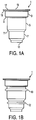
- Figure 1A shows a profile of a preferred embodiment in accordance with the present invention.
- the filter column 1 includes a first body portion 3, a second body portion 5, and a third body portion 7.
- the filter column 1 also contains a first bearing surface 9 and a second bearing surface 11 located between body portions 3, 5, 7 as illustrated.
- the bearing surfaces are intended to permit placement of the filter column 1 in various collection tubes ( e.g ., see Figures 4 and 5 .) Accordingly, the present invention contemplates that the bearing surfaces, either alone, or along with body portion(s) adjacent to a bearing surface, serve to provide stability of a filter column within a collection tube.
- bearing surfaces 9, 11 are located at the intersection of the respective body portions, in other variations of the invention, and within the scope of the appended claims, the bearing surfaces may be located anywhere along the various body portions. As illustrated in Figure 1B where the bearing surfaces 10, 12, are located along respective body portions of a filter column 1. Additionally, while bearing surfaces 9, 11, are illustrated as being tapered, the invention is not limited as such.
- Preferred embodiments of the invention also include filter columns with more than three body portions.
- the variation of the spin-column depicted in Figure 1 further includes an outer rim 17 adjacent to a top 15 of the filter column 1.
- the outer rim 17 may also provide an additional bearing surface 19 and may also aid in grasping and manipulating the filter column 1.
- the bottom of the filter column may be reduced in diameter 13 to assist in retaining a filter (not shown) within the filter column 1.
- the body of the filter column may be adapted as required to accommodate any particular filtration process for example, centrifugation, vacuum filtering, or any known filtering process.
- the filter column may also include a manifold to accommodate the vacuum.
- Such modifications are well known to those familiar with filter columns and methods of using such devices.
- the dimensions of the body portions 3, 7 are selected so that the filter column 1 may fit into various collection tubes that are sized for the respective body portion and bearing surface.
- the invention include sizing of a filter column to include body portions and bearing surfaces that accommodate both a 1.5 - 2.0 mL and a 0.5 mL or a 0.2 mL microcentrifuge tube.
- An example of such tubes includes PGC Scientifics No. 16-8105-52 (1.5 mL) supplied by PGC Scientifics Corporation of Maryland, Eppendorf No. 22 36 430-8 (0.5 mL) supplied by Eppendorf AG of Germany, and GeneAmp® No. N801-0611 (0.5 mL) supplied by Perkin-Elmer Life Science of Massachusetts.
- the opening diameter for a 1.5 mL - 2.0 mL microcentrifuge tube may range from 8.1 - 9.4 mm (0.32 - 0.37 in).
- the opening diameter for a 0.5 mL microcentrifuge tube may range from 6.6 - 6.9 mm (0.26 - 0.27 in).
- the definition of diameter of the filter column may includes any such external feature as crush ribs, buttress, collar, or any other feature that may be present on a portion of a filter column body that is intended for insertion into a collection tube.
- the filter column of the invention comprises deformable ribs as defined in appended claim 1.
- the invention may be suited for use with the tubes described above, the invention is not limited to compatibility with such tubes.
- embodiments of the inventive device described herein are discussed for use with existing microcentrifuge tubes ranging in size from 0.5 mL capacity to 1.5 - 1.5 mL capacity, the invention is not limited as such. Instead, within the scope of the appended claims, the inventive device may be applied to collection tubes as described herein, centrifuge tubes of any size, or any type of collection tube where a benefit from the improvements of the current invention are desirable.
- the invention may be adapted to accommodate any number of combinations of large and small collection tubes, including, but not limited to a filter column adapted to accommodate a large 0.5 mL tube and a small 0.2 mL tube, or a filter column adapted to accommodate a large 1.5 mL tube and a small 0.2 mL tube.
- the height of the filter columns of the present invention is selected so that the filter column along with the particular collection tube used will fit within the centrifuge apparatus (e.g ., an Eppendorf 5415C centrifuge supplied by Eppendorf AG of Germany.)
- the centrifuge apparatus e.g ., an Eppendorf 5415C centrifuge supplied by Eppendorf AG of Germany.
- the height which protrudes from the 0.5 mL microcentrifuge tube i.e., referring to Figure 1A , the height from the top of bearing surface 11 to the top of the device
- the height from the top of bearing surface 11 to the top of the device must be below 15.9 mm (0.625 in) preferably below 12.7 mm (0.5) in.
- the filter columns of the present invention may be fabricated from materials readily known to those familiar with existing filter columns. Such materials include, but are not limited to, polypropylene or polycarbonate. Polyethylene, Fluoropolymers such as polytetrafluoroethylene and polyvinylidine flouride, Polyarylene ether ketones, and co-polymers. It is often desirable to use a material which is thermoplastic to allow molding of the columns. The columns can also be machined out of appropriate materials. In some cases, it is desirable to choose materials which permit sterilization of the filter column thereby allowing the filter column, filter, and sample to be nuclease-free.
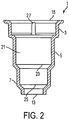
- Figure 2 illustrates the internal body structure of a preferred embodiment of a filter column of the present invention.
- Liquid solutions may be loaded into the top of the filter column 15.
- liquid solutions include the nucleotide-containing solution, wash or rinsing solutions and an elution buffer (water or TE).
- the nucleic acid solution can be from a lysate ( e.g . isolated directly from cells), or nucleic acids from a reaction mixture.
- the nucleic acids from reaction mixtures could be from reactions such as PCR, DNA or RNA polymerization, reverse transcription, etc.
- the nucleic acid solution Before being loaded onto the filter column the nucleic acid solution is usually combined with a binding buffer containing a chaotropic agent to aid in binding the nucleic acid to the filter.
- compositions of binding buffers, wash or rinsing solutions and elution buffer is well known in the field and can be found in US patents 5,075,430 to Little , 5,808,041 to Padhye , and 5,652,141 to Henco .
- the preferred embodiment of the invention depicted in Figure 2 also illustrates a vent 27.
- the vent 27 may be located along an interior surface of a passageway 21 of a filter column 1 but will be placed in fluid communication with an exterior of the filter column 1.
- the vent 27 permits venting of pressure within the passageway 21 during placement of a lid (not shown) in the top opening 15 of the filter column 1. Without a vent, the placement of a lid could increase pressure within the passageway 21 such that sample material is forced out of the bottom 13 of the filter column 1. Although such displacement of the material may not have an effect on the function of a device of the present invention, such an occurrence may be undesirable. It is contemplated that the device 1 may have any number of vents.
- vents may be placed randomly or spaced evenly apart on a wall of a passageway. In one variation (not shown) four vents are placed at intervals of 90° along the walls of the passageway. It is further contemplated that a vent may be placed in another location in the filter column 1 or even within a lid (not shown) itself.
- the preferred filter column 1 of the present invention also allows for varying placement of a filter (not shown) within a passageway 21 of the filter column 1.
- a filter (not shown) within a passageway 21 of the filter column 1.
- placement of a filter in a bottom 23 of the second body portion 5 permits the filter column 1 to provide a certain volume capacity.
- the volume capacity of the filter column 1 can increase by changing the location of the filter to a bottom 25 of the third body portion 7. Accordingly, the same filter column 1 body may be used for varying application.
- a filter can be located in the lowest chamber.
- locating the filter towards a middle chamber reduces the volume of fluid that may be added but permit a larger filter surface area as the diameter of the middle chamber may be greater than the diameter of a lower chamber.
- a high surface area fiber glass filter e.g., a borosilicate glass
- the filter may be one that is adapted to isolate nucleic acids from a liquid sample by, for example, centrifugation, vacuum filtering, or any other filtering method.
- Surface area refers to the total surface area of all the fibers and not just the area of the disk. The total surface area may range between 1,000 mm 2 and 50,000 mm 2 .
- filter columns of the present invention may have a microliter capacity greater than 200 microliters. Another variation of the filter column having a microliter capacity ranging between 50 microliters and 1000 microliters. The microliter capacity is defined by the volume within a passageway of the filter column that above the filter.
- Securing of the filter may be accomplished, for example, by placement of a disk of porous substrate material (not shown) at position 25.
- a filter membrane (not shown) is placed on top of the substrate material.
- a retaining ring (not shown) is added such that there is an interference between the retaining ring and the wall of the passageway. Accordingly, the retaining ring secures the filter on the porous substrate.
- Another means of securing the filter is to mold an integral grating within the passageway to seat the filter.
- Figure 3 illustrates placement of a filter using the porous substrate and retaining ring.
- FIG. 3 illustrates a cut-away profile view of a preferred embodiment of a filter column 1 of the present invention.
- the illustration shows a filter 29 held in the lower portion of the filter column 1.
- the filter 29 is held between a porous support membrane 31, which has the same diameter as the interior of the lower portion of the spin filter 1.
- the support membrane 31 is retained in place by the shoulder formed by the reduced diameter of the bottom 13 of the device.
- the filter 29 may be fixed against the support membrane 31 by a retaining ring 33 which fits securely against the inner wall of the lower portion of the filter column 1.
- the present invention is not limited to the previous illustration. It will be apparent to those skilled with previously known filter columns to provide other means of retaining the filter within a filter column.
- An example of a filter for use with the invention includes a borosilicate glass fiber filter.
- the device may also contain filters of other types such as polymeric membranes, and may also contain other functional groups for purification of the nucleic acid such as ion exchange groups or groups which would specifically bind nucleic acid sequences.
- Another useful material for the porous substrate is a sintered polyethylene or polypropylene as supplied by Porex® of Fairburn, Georgia or GenPore® of Reading, Pennsylvania.
- the porous substrate is comprised of a hydrophobic material in order to minimize holdup of the aqueous solution. It was found that pore sizes in the range of 10 micrometre to 150 micrometres worked well.
- the primary function of the porous material is support for the filter. It is possible to have the porous support as integral to the device.
- the porous support can also be in the form of an open grating.
- Figure 4 illustrates a preferred embodiment of a filter column 1 of the present invention that is mated with a standard collection tube 35 of a first size (e.g., a 1.5 mL tube.)
- Standard collection tubes contain an integral body made of polymers such as polypropylene and have a standard inner diameter.
- the second body portion 5 of the filter column 1 may fit securely against an inner walls of the collection tube 35.
- the first bearing surface 9 may rest against a shoulder formed by a rim 37 of the collection tube 35. Accordingly, when the tube 35 and filter column 1 spin in the centrifuge, liquid placed into the filter column 1 is forced through a filter 29 and collects in the collection tube 35.
- the sizing of the first body portion 5 along with the bearing surface 9 permits stable placement of the filter column 1 within in the collection tube 35. After centrifugation, the filter column can be easily removed from the used collection tube, and placed into a new collection tube or placed back into the original tube.
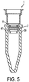
- Figure 5 illustrates the filter column 1 of Figure 4 placed within a collection tube 39 (e.g., a 0.5 mL tube) that is smaller than the tube illustrated in Figure 4 .
- a collection tube 39 e.g., a 0.5 mL tube
- the third body portion 7 of the filter column 1 fits securely into the inner walls of the collection tube 39.
- a bearing surface 11 of the filter column 1 seats against a rim 41 of the collection tube 39.
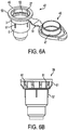
- FIG. 6A shows another preferred embodiment of a filter column 42 of the present invention having features which may be applied to any embodiment of the invention disclosed herein, within the scope of the appended claims.
- the filter column 42 includes a lid 45 having a portion 47 which may be removably secured within a first end 49 of the filter column 42.
- the lid 45 may assist in preventing contamination of the filter column 42 and any solutions loaded therein.
- this embodiment of the filter column 42 contains a vent 27.
- the present invention also contemplates a lid as being discrete from a filter column.
- the preferred embodiment of the inventive filter column 42 also may include one or more snap-fit beads or ridges 53 to assist in retention of a lid 45.
- the ridge 53 is included in the in a portion of a passageway in a first body portion 3 of the filter column 42.
- the lid 45 and hinge 51 may be attached to the underside of an outer rim 55 ( e.g., subflush to the rim 55) of the filter column 42. This placement allows the outer rim 55 to be mated to other devices as required. (e.g ., a EtracSureTM sample extraction device useful for laser capture microdissection supplied by Arcturus Engineering of Mountain View, CA.)
- deformable ribs 57 which are located along an outside surface of the filter column 42, as defined in appended claim 1.
- the deformable ribs 57 assist in securing the filter column 42 in a slightly larger diameter tube (e.g., a 2.0 mL tube) by increasing a diameter of the filter column 42. Accordingly, these ribs deform upon insertion of the filter column 42 into a tube having a diameter slightly larger than the corresponding body portion upon which the ribs 57 are situated.
- the number and design of the deformation ribs 57 may vary as needed, however, the ribs should be placed on a portion of the filter column that accommodates the varying sizes of tubes.
- the invention also contemplates deformation ribs 57 which are either plastically or elastically deformable, or exhibit a limited degree of plastic or elastic deformation.
- Figure 6B illustrates another preferred embodiment of the invention in which a filter column 59 contains at least one protrusion 61 which extends radially away from the filter column 59.
- protrusions 61 may serve as "finger grips" to increase the ease with which the filter column 59 may be manipulated.
- Figures 7-9 represent a flow diagram illustrating isolation of nucleic acids such as DNA or RNA from a biological material 80 using a filter column of the present invention.
- Figure 7 represents the first step of placing a lysate 82 of biological material 80 in a collection tube 84. This lysate 82 is spun to remove large lytic debris, and the "cleared" lysate is then applied to the top of a filter column 86 of the present invention.
- the nucleic acid containing solution does not have to come directly from lysis of biological materials.
- This method can also purify nucleic acids following nucleic acid amplification, enzymatic restriction digestion, ligation, extension and virtually any solution containing significant nucleic acids.
- nucleic acid solutions where small amounts of nucleic acid solutions are used, it is desirable to pre-wet the filter column with binding buffer before applying the nucleic acid solution.
- Figure 8A illustrates the solution passing though a filter of the filter column 86 after centrifugation, during which the nucleic acids bind to the filter.
- the flow-through solution (from which the nucleotides have been mostly extracted) is retained at the bottom of a collection tube 88.
- tubes 82, 84 are discarded after use.
- the binding buffer (flow through) is discarded, and the filter column is replaced in a collection tube (either a new tube or the same tube).
- Figure 8B represents repeated washing of the filter column 86 with a washing buffer and centrifuging after each addition of washing solution into the top of the filter column. Once again the flow-through accumulated at the bottom of the tube 88 is discarded.
- Figure 9 represents the last step of transferring the filter column 86 of the present invention into a smaller 0.5 mL tube 92 and the addition of a small volume of elution buffer into the filter column 86.
- the inventive filter column permits use of more than one collection tube.
- centrifugation steps can take place in a standard bench-top microcentrifuge (for example, Eppendorf 5415C), usually at accelerations less than 20,000g.
- the biological material used with the filter column may also be provided by laser capture microdissection extraction device as described in U.S. patent application serial No. 09/844,187 , entitled "LASER CAPTURE MICRODISSECTION (LCM) EXTRACTION DEVICE AND DEVICE CARRIER, AND METHOD FOR POST-LCM FLUID PROCESSING.”
- a filter column 1 attached to a LCM extraction device flange interface 94 which seats a laser capture microdissection extraction device 96.
- the biological material will be located on a bottom surface of the extraction device 96.
Landscapes
- Chemical & Material Sciences (AREA)
- Health & Medical Sciences (AREA)
- General Health & Medical Sciences (AREA)
- Analytical Chemistry (AREA)
- Life Sciences & Earth Sciences (AREA)
- Biochemistry (AREA)
- Physics & Mathematics (AREA)
- General Physics & Mathematics (AREA)
- Immunology (AREA)
- Pathology (AREA)
- Hematology (AREA)
- Clinical Laboratory Science (AREA)
- Chemical Kinetics & Catalysis (AREA)
- Apparatus Associated With Microorganisms And Enzymes (AREA)
Description
- This invention relates to filtration filter columns and methods of filtering therewith. More specifically, this invention relates to system and methods for isolating nucleic acids such as ribonucleic acid (RNA) and deoxyribonucleic acid (DNA) from other materials such as enzymes, salts, buffers, small molecules, and cellular debris.
- Isolation and purification of nucleic acids play a central role in modern molecular biology, and increasingly in medicine. Both laboratory and diagnostic research require the use of nucleic acids in gene cloning and genetic analysis. Many of these techniques require keeping ribonucleic acid (RNA) or deoxyribonucleic acid (DNA) pure and free of contamination. In many instances, the availability of small amounts of starting sample material poses a problem during isolation of the nucleic acid. The limited amount of sample material makes the need to limit loss of the sample material a critical concern.
- A known method for isolating nucleic acids from a small amount of starting material includes the use of a spin filter column ("filter column") that contains a nucleic acid binding material (i.e., a filter). Examples of binding material/filters include silicas like glass powder, silica particles, glass microfibers, diatomaceous earth, etc. These filters are often associated with a "filter surface area." This filter surface area is not limited to the surface area of a side of the filter. Instead, since the filters are usually comprised of microscopic fibers, particles, porous substances, etc., the filter surface area is actually defined by the surface area of the components which comprise the filter. For example, a filter that comprises glass microfibers may have a filter surface area defined by the surface area of the microfibers within the filter (either all of the microfibers or a portion thereof).
- In some cases, filter columns may isolate nucleic acids directly from cells or biological tissue. In the first step a filter column is inserted into a microcentrifuge tube (e.g., a 1.5 ml tube) and a solution containing nucleic acids along with undesirable impurities is loaded into the top of the filter column. Depending upon the application, the starting material containing the nucleic acids is prepared from cells that have been treated with a disrupting solution causing the release of the nucleic acids. Alternatively, the nucleic acid solution is the product of an earlier reaction step. In either case, the nucleic acid binds to the filter column filter in the presence of a chaotropic agent. Then the filter column is centrifuged in a microcentrifuge. Centrifugation forces the solution through the filter column's filter and binds the nucleic acid to the filter. Next, the filter with the nucleic acids bound therein is washed by applying a washing solution to the top of the filter column, and centrifuging again. After each wash the filter column can be removed from the collection tube so that the collection tube may be emptied. Finally, placement of an elution buffer (usually water having a specific pH) at the top of the column and applying centrifugation elutes the nucleic acid that is bound to the filter. Given the proper pH, the nucleic acid elutes into the liquid, and then collects into the collection tube. It is important to note that the volumes of the binding and wash solutions can be relatively large, thus necessitating the use of a larger (1.5 - 2.0 mL) tube. On the other hand, the volumes for elution are often smaller, making it desirable to have a smaller tube for the elution step. Eluting directly into a smaller tube allows one to proceed to the next reaction step in the small tube, rather than having to pipette out of the large tube. As discussed herein, use of a pipette is undesirable as it introduces the risk of loss of samples as well as contamination of the sample. Moreover, as described herein, there are additional benefits in keeping the sample solution in a smaller tube.
- Several companies provide kits that include filter columns designed to use this technique for isolating nucleic acids. QIAGEN, Promega, and Boehringer Mannheim GmbH offer filter columns based on the above described principle However, existing filter columns cannot be used interchangeably with collection tubes of different sizes. Instead, these previously known filter columns only fit into a single size collection tube (e.g., a standard 1.5 - 2.0 mL microcentrifuge tube). An example of a filter device and kit for isolation and purification of nucleic acids and the like from heterogeneous biological samples is given in
US 5,438,128 . The device comprises a membrane assembly comprised of layers of microporous, polymeric membranes functionalized with ion-exchange groups, and is re-usable for like samples. - This limitation presents a problem as many applications may benefit if a single filter column could be interchanged with collection tubes of multiple sizes. For example, given a small amount of nucleic acid in the starting material, it is best to elute the purified nucleic acid into a very small volume of fluid so that nucleic acid does not become too dilute in the fluid. Obviously, the resulting combination of elution buffer and nucleic acid will occupy a small volume. Many applications that require processing of nucleic acid may benefit when storing this small volume of material in a smaller sized collection tube. For instance, an application such as amplification of the purified DNA by polymerase chain reaction (PCR) requires placement of the nucleic acid into a thin-walled 0.5 mL or 0.2 mL microcentrifuge tube.
- Accordingly, it may seem ideal to use a smaller filter column which is specifically designed to fit a 0.5 mL or 0.2 mL microcentrifuge tube. However, a significant drawback is that these smaller filter columns limit the amount of wash solution that can be passed through the column with each wash. This limitation necessitates additional wash steps and increased handling of the filter column and microcentrifuge tube, thus presenting an undesirable increased risk of contamination. Also, as discussed above, the requirement of large volumes of binding and wash solutions often necessitate the use of a larger collection tubes (e.g., a 1.5 - 2.0 mL microcentrifuge tube).
- The remaining alternative is to use a filter column specifically designed to fit into a larger collection tube (e.g., a 1.5 mL - 2.0 microcentrifuge tube). While this alternative minimizes the additional wash steps and increased handling discussed above, the alternative presents additional problems. For instance, after purification, the nucleic acid solution must be eluted from the filter column into an appropriately sized 1.5 mL - 2.0 mL microcentrifuge tube. As discussed above, many applications may benefit by storing the elution buffer and nucleic acid in a smaller sized microcentrifuge tube. Consequently, the elution buffer and nucleic acid must then be transferred (e.g., by aspiration) into a smaller (e.g., 0.5 mL) tube. Again, this extra transfer step introduces the undesirable potentials of contamination and loss of some of the nucleic acid.
-
US 4,214,993 describes a filter column (separating column) for use with a single size of tube. The column forms part of an apparatus comprising three pieces which may be nested together to form a stacked array. The three pieces are a cap, an extraction cartridge housing the column, and a primary recovery cup (tube). A secondary recovery cup may also be nested onto the lower end of the primary cup. Each piece has an enlarged upper portion forming an exterior step which facilitates mounting in the swinging bucket of a centrifuge. -
WO 93/01494 A1 - In view of the above, there remains a need to use different-sized collection tubes with a single filter column. The ability to use different-sized collection tubes with a single filter column overcomes the problems associated with the existing art.
- The invention described herein addresses the problems discussed above. Moreover, the invention described herein allows centrifugation from one filter column into at least two distinct sizes of collection tubes. The disclosed invention may be used with commercially available collection tubes.
- This invention relates to filtration filter column devices and methods of filtering therewith, as defined in the appended claims. The invention includes a filter column filter which has a plurality of bearing surfaces along with a plurality of body portions of varying outer diameters each of which is adapted to seat on respective collection tubes of different sizes.
- Accordingly, a first aspect of the invention is directed to a filter column comprising: a body having a passageway extending therethrough, said body comprising at least a first body portion, a second body portion, and a third body portion, where an outer diameter of said first body portion is greater than an outer diameter of said second body portion, and where said outer diameter of said second body portion is greater than an outer diameter of said third body portion; a filter located within said passageway, said filter adapted to isolate nucleic acids from a liquid sample; a first bearing surface adapted to rest against the rim of a first collection tube where an outer diameter of the second body portion below the first bearing surface is adapted to fit securely with the first collection tube, wherein the first collection tube is a 1.5 - 2.0 mL centrifuge tube; and a second bearing surface adapted to rest against the rim of a second collection tube where an outer diameter of the third body portion below the second bearing surface is adapted to fit securely with the second collection tube and wherein the opening of the first collection tube is greater than the opening of the second collection tube, wherein the second collection tube is a 0.5 mL or a 0.2 mL centrifuge tube, wherein a first end of said body is adapted to seat a laser capture microdissection extraction device flange interface, and wherein deformable ribs are located along an outside surface of a body portion of the filter column that is adapted to accommodate said first or second collection tubes.
- A preferred embodiment of the invention includes a lid which may be either discrete from the filter column or may be integral with the filter column body. In the latter case, the lid may be joined to the filter column body by a hinge or other member.
- A preferred embodiment of the invention includes a filter column which contains vents within a passageway of the filter column. The vents permit placement of a lid on the filter column without increasing the pressure within the passageway thereby causing sample material to be forced out of the filter column.
- The filter column of the invention includes deformable ribs placed about an outer surface of a body portion of the filter column. Such deformable ribs may assist placement of the filter column within closely varying sizes of collection tubes.
- The invention includes kits for isolation of nucleic acid from a solution containing nucleic acids and contaminating material. The kit contains a filter column according to the first aspect, collection tubes, binding buffer, wash solutions and elution buffer.
- A second aspect of the present invention is directed to a method for isolating a nucleic acid material comprising: providing a filter column according to the first aspect comprising: fitting the filter column into the first collection tube at the first bearing surface such that an outer diameter of the second body portion below the first bearing surface fits securely with the first collection tube; attaching a laser capture microdissection extraction device flange interface which seats a laser capture microdissection extraction device with biological material located on the bottom surface; transferring the solution containing nucleic acid to the filter of the filter column in the presence of an agent capable of promoting binding of the nucleic acid material to the filter; transferring the solution from the filter column to the first collection tube via centrifugal force; washing the filter column filter with a wash solution; removing the filter column from the first collection tube; providing a second collection tube wherein the opening of the second collection tube is smaller than the opening of the first collection tube; placing the filter column in the second collection tube at the second bearing surface such that an outer diameter of the third body portion below the second bearing surface fits securely with the second collection tube; and applying elution buffer and eluting the nucleic acid material from the filter column by centrifugal force.
-
-
Figure 1A and 1B illustrate preferred embodiments of filter columns of the present invention appropriate for mating with collection tubes of varying sizes. -
Figure 2 illustrates a sectional view of a preferred embodiment according to the invention. -
Figure 3 illustrates a cut-away profile view of a preferred embodiment of a filter column of the present invention showing a filter. -
Figure 4 illustrates a sectional view of a preferred embodiment of filter column of the present invention removably seated in a first collection tube. -
Figure 5 illustrates a sectional view of the filter column illustrated inFigure 4 removably seated in a second collection tube being of a different size than the first collection tube ofFigure 4 . -
Figure 6A and 6B illustrate additional preferred embodiments of the invention that may be combined with any variation of the invention singly or in combination, within the scope of the appended claims. -
Figures 7, 8 and 9 illustrate a preferred embodiment of a method of the present invention. -
Figure 10 illustrates a filter column of a preferred embodiment of the present invention for use with a laser capture microdissection device. - The following discussion of the preferred embodiments of the invention and the reference to the attached drawings are for explanatory purposes and do not exhaustively represent the possible combinations and embodiments of the invention. Those skilled in the art will readily appreciate that many variations may be derived using the following description. The following examples are intended to convey certain principles of the invention. These examples are not intended to limit the scope of the claims to any particular example. It is understood that the claims are to be given their broadest reasonable interpretation in view of the description herein, any prior art, and the knowledge of those of ordinary skill in the field.
-
Figure 1A shows a profile of a preferred embodiment in accordance with the present invention. In this embodiment, thefilter column 1 includes afirst body portion 3, asecond body portion 5, and athird body portion 7. Thefilter column 1 also contains afirst bearing surface 9 and asecond bearing surface 11 located betweenbody portions filter column 1 in various collection tubes (e.g., seeFigures 4 and5 .) Accordingly, the present invention contemplates that the bearing surfaces, either alone, or along with body portion(s) adjacent to a bearing surface, serve to provide stability of a filter column within a collection tube. Such stable placement being necessary for the intended use of the filter column (e.g., during centrifugation, vacuum filtering, handling, adding/removing material, etc.) Furthermore, although bearingsurfaces Figure 1B where the bearing surfaces 10, 12, are located along respective body portions of afilter column 1. Additionally, while bearingsurfaces - Preferred embodiments of the invention also include filter columns with more than three body portions. The variation of the spin-column depicted in
Figure 1 further includes anouter rim 17 adjacent to a top 15 of thefilter column 1. Theouter rim 17 may also provide anadditional bearing surface 19 and may also aid in grasping and manipulating thefilter column 1. The bottom of the filter column may be reduced indiameter 13 to assist in retaining a filter (not shown) within thefilter column 1. - It is noted that the body of the filter column may be adapted as required to accommodate any particular filtration process for example, centrifugation, vacuum filtering, or any known filtering process. For example, if a filter column of the present invention is intended for use with vacuum filtering, the filter column may also include a manifold to accommodate the vacuum. Such modifications are well known to those familiar with filter columns and methods of using such devices.
- The dimensions of the
body portions filter column 1 may fit into various collection tubes that are sized for the respective body portion and bearing surface. The invention include sizing of a filter column to include body portions and bearing surfaces that accommodate both a 1.5 - 2.0 mL and a 0.5 mL or a 0.2 mL microcentrifuge tube. An example of such tubes includes PGC Scientifics No. 16-8105-52 (1.5 mL) supplied by PGC Scientifics Corporation of Maryland, Eppendorf No. 22 36 430-8 (0.5 mL) supplied by Eppendorf AG of Germany, and GeneAmp® No. N801-0611 (0.5 mL) supplied by Perkin-Elmer Life Science of Massachusetts. For example, the opening diameter for a 1.5 mL - 2.0 mL microcentrifuge tube may range from 8.1 - 9.4 mm (0.32 - 0.37 in). The opening diameter for a 0.5 mL microcentrifuge tube may range from 6.6 - 6.9 mm (0.26 - 0.27 in). It is intended that, where appropriate, the definition of diameter of the filter column may includes any such external feature as crush ribs, buttress, collar, or any other feature that may be present on a portion of a filter column body that is intended for insertion into a collection tube. The filter column of the invention comprises deformable ribs as defined in appendedclaim 1. - While the invention may be suited for use with the tubes described above, the invention is not limited to compatibility with such tubes. Moreover, although embodiments of the inventive device described herein are discussed for use with existing microcentrifuge tubes ranging in size from 0.5 mL capacity to 1.5 - 1.5 mL capacity, the invention is not limited as such. Instead, within the scope of the appended claims, the inventive device may be applied to collection tubes as described herein, centrifuge tubes of any size, or any type of collection tube where a benefit from the improvements of the current invention are desirable. Furthermore, the invention may be adapted to accommodate any number of combinations of large and small collection tubes, including, but not limited to a filter column adapted to accommodate a large 0.5 mL tube and a small 0.2 mL tube, or a filter column adapted to accommodate a large 1.5 mL tube and a small 0.2 mL tube.
- The height of the filter columns of the present invention is selected so that the filter column along with the particular collection tube used will fit within the centrifuge apparatus (e.g., an Eppendorf 5415C centrifuge supplied by Eppendorf AG of Germany.) For example, for a 0.5 mL microcentrifuge tube to fit in the centrifuge previously listed, the height which protrudes from the 0.5 mL microcentrifuge tube (i.e., referring to
Figure 1A , the height from the top of bearingsurface 11 to the top of the device) must be below 15.9 mm (0.625 in) preferably below 12.7 mm (0.5) in. - The filter columns of the present invention may be fabricated from materials readily known to those familiar with existing filter columns. Such materials include, but are not limited to, polypropylene or polycarbonate. Polyethylene, Fluoropolymers such as polytetrafluoroethylene and polyvinylidine flouride, Polyarylene ether ketones, and co-polymers. It is often desirable to use a material which is thermoplastic to allow molding of the columns. The columns can also be machined out of appropriate materials. In some cases, it is desirable to choose materials which permit sterilization of the filter column thereby allowing the filter column, filter, and sample to be nuclease-free.
-
Figure 2 illustrates the internal body structure of a preferred embodiment of a filter column of the present invention. Liquid solutions may be loaded into the top of thefilter column 15. Typically, liquid solutions include the nucleotide-containing solution, wash or rinsing solutions and an elution buffer (water or TE). The nucleic acid solution can be from a lysate (e.g. isolated directly from cells), or nucleic acids from a reaction mixture. The nucleic acids from reaction mixtures could be from reactions such as PCR, DNA or RNA polymerization, reverse transcription, etc. Before being loaded onto the filter column the nucleic acid solution is usually combined with a binding buffer containing a chaotropic agent to aid in binding the nucleic acid to the filter. The compositions of binding buffers, wash or rinsing solutions and elution buffer is well known in the field and can be found inUS patents 5,075,430 to Little ,5,808,041 to Padhye , and5,652,141 to Henco . - The preferred embodiment of the invention depicted in
Figure 2 also illustrates avent 27. Thevent 27 may be located along an interior surface of apassageway 21 of afilter column 1 but will be placed in fluid communication with an exterior of thefilter column 1. Thevent 27 permits venting of pressure within thepassageway 21 during placement of a lid (not shown) in thetop opening 15 of thefilter column 1. Without a vent, the placement of a lid could increase pressure within thepassageway 21 such that sample material is forced out of the bottom 13 of thefilter column 1. Although such displacement of the material may not have an effect on the function of a device of the present invention, such an occurrence may be undesirable. It is contemplated that thedevice 1 may have any number of vents. These vents may be placed randomly or spaced evenly apart on a wall of a passageway. In one variation (not shown) four vents are placed at intervals of 90° along the walls of the passageway. It is further contemplated that a vent may be placed in another location in thefilter column 1 or even within a lid (not shown) itself. - As illustrated in
Figure 2 , thepreferred filter column 1 of the present invention also allows for varying placement of a filter (not shown) within apassageway 21 of thefilter column 1. For example, placement of a filter in a bottom 23 of thesecond body portion 5 permits thefilter column 1 to provide a certain volume capacity. The volume capacity of thefilter column 1 can increase by changing the location of the filter to a bottom 25 of thethird body portion 7. Accordingly, thesame filter column 1 body may be used for varying application. To maximize the volume of fluid that can be added to a filter column of the present invention, a filter can be located in the lowest chamber. Moreover, locating the filter towards a middle chamber reduces the volume of fluid that may be added but permit a larger filter surface area as the diameter of the middle chamber may be greater than the diameter of a lower chamber. For the filter, it is desirable to have a high surface area fiber glass filter , (e.g., a borosilicate glass). The filter may be one that is adapted to isolate nucleic acids from a liquid sample by, for example, centrifugation, vacuum filtering, or any other filtering method. Surface area refers to the total surface area of all the fibers and not just the area of the disk. The total surface area may range between 1,000 mm2 and 50,000 mm2. Moreover, filter columns of the present invention may have a microliter capacity greater than 200 microliters. Another variation of the filter column having a microliter capacity ranging between 50 microliters and 1000 microliters. The microliter capacity is defined by the volume within a passageway of the filter column that above the filter. - Securing of the filter may be accomplished, for example, by placement of a disk of porous substrate material (not shown) at
position 25. A filter membrane (not shown) is placed on top of the substrate material. Optionally, a retaining ring (not shown) is added such that there is an interference between the retaining ring and the wall of the passageway. Accordingly, the retaining ring secures the filter on the porous substrate. Another means of securing the filter is to mold an integral grating within the passageway to seat the filter.Figure 3 illustrates placement of a filter using the porous substrate and retaining ring. -
Figure 3 illustrates a cut-away profile view of a preferred embodiment of afilter column 1 of the present invention. The illustration shows afilter 29 held in the lower portion of thefilter column 1. In this embodiment, thefilter 29 is held between aporous support membrane 31, which has the same diameter as the interior of the lower portion of thespin filter 1. In this embodiment, thesupport membrane 31 is retained in place by the shoulder formed by the reduced diameter of the bottom 13 of the device. Thefilter 29 may be fixed against thesupport membrane 31 by a retaining ring 33 which fits securely against the inner wall of the lower portion of thefilter column 1. The present invention is not limited to the previous illustration. It will be apparent to those skilled with previously known filter columns to provide other means of retaining the filter within a filter column. An example of a filter for use with the invention includes a borosilicate glass fiber filter. The device may also contain filters of other types such as polymeric membranes, and may also contain other functional groups for purification of the nucleic acid such as ion exchange groups or groups which would specifically bind nucleic acid sequences. Another useful material for the porous substrate is a sintered polyethylene or polypropylene as supplied by Porex® of Fairburn, Georgia or GenPore® of Reading, Pennsylvania. In some variations of the invention it is desirable that the porous substrate is comprised of a hydrophobic material in order to minimize holdup of the aqueous solution. It was found that pore sizes in the range of 10 micrometre to 150 micrometres worked well. The primary function of the porous material is support for the filter. It is possible to have the porous support as integral to the device. The porous support can also be in the form of an open grating. -
Figure 4 illustrates a preferred embodiment of afilter column 1 of the present invention that is mated with astandard collection tube 35 of a first size (e.g., a 1.5 mL tube.) Standard collection tubes contain an integral body made of polymers such as polypropylene and have a standard inner diameter. As shown inFigure 4 , thesecond body portion 5 of thefilter column 1 may fit securely against an inner walls of thecollection tube 35. Thefirst bearing surface 9 may rest against a shoulder formed by arim 37 of thecollection tube 35. Accordingly, when thetube 35 andfilter column 1 spin in the centrifuge, liquid placed into thefilter column 1 is forced through afilter 29 and collects in thecollection tube 35. In this embodiment, the sizing of thefirst body portion 5 along with the bearingsurface 9 permits stable placement of thefilter column 1 within in thecollection tube 35. After centrifugation, the filter column can be easily removed from the used collection tube, and placed into a new collection tube or placed back into the original tube. -
Figure 5 illustrates thefilter column 1 ofFigure 4 placed within a collection tube 39 (e.g., a 0.5 mL tube) that is smaller than the tube illustrated inFigure 4 . As illustrated inFigure 5 , thethird body portion 7 of thefilter column 1 fits securely into the inner walls of thecollection tube 39. During centrifugation, a bearingsurface 11 of thefilter column 1 seats against arim 41 of thecollection tube 39. -
Figure 6A shows another preferred embodiment of afilter column 42 of the present invention having features which may be applied to any embodiment of the invention disclosed herein, within the scope of the appended claims. In this embodiment thefilter column 42 includes alid 45 having aportion 47 which may be removably secured within afirst end 49 of thefilter column 42. Thelid 45 may assist in preventing contamination of thefilter column 42 and any solutions loaded therein. As shown, this embodiment of thefilter column 42 contains avent 27. Although this embodiment depicts thelid 45 as being integral with thefilter column 42 via ahinge 51, the invention is not limited as such. For example, the present invention also contemplates a lid as being discrete from a filter column. - As illustrated in
Figure 6A , the preferred embodiment of theinventive filter column 42 also may include one or more snap-fit beads orridges 53 to assist in retention of alid 45. In this variation theridge 53 is included in the in a portion of a passageway in afirst body portion 3 of thefilter column 42. As depicted inFigure 6A , thelid 45 and hinge 51 may be attached to the underside of an outer rim 55 (e.g., subflush to the rim 55) of thefilter column 42. This placement allows the outer rim 55 to be mated to other devices as required. (e.g., a EtracSure™ sample extraction device useful for laser capture microdissection supplied by Arcturus Engineering of Mountain View, CA.) - Another aspect of the invention depicted in
Figure 6A isdeformable ribs 57 which are located along an outside surface of thefilter column 42, as defined in appendedclaim 1. Thedeformable ribs 57 assist in securing thefilter column 42 in a slightly larger diameter tube (e.g., a 2.0 mL tube) by increasing a diameter of thefilter column 42. Accordingly, these ribs deform upon insertion of thefilter column 42 into a tube having a diameter slightly larger than the corresponding body portion upon which theribs 57 are situated. The number and design of thedeformation ribs 57 may vary as needed, however, the ribs should be placed on a portion of the filter column that accommodates the varying sizes of tubes. The invention also contemplatesdeformation ribs 57 which are either plastically or elastically deformable, or exhibit a limited degree of plastic or elastic deformation. -
Figure 6B illustrates another preferred embodiment of the invention in which afilter column 59 contains at least oneprotrusion 61 which extends radially away from thefilter column 59.Such protrusions 61 may serve as "finger grips" to increase the ease with which thefilter column 59 may be manipulated. -
Figures 7-9 represent a flow diagram illustrating isolation of nucleic acids such as DNA or RNA from abiological material 80 using a filter column of the present invention.Figure 7 represents the first step of placing alysate 82 ofbiological material 80 in acollection tube 84. Thislysate 82 is spun to remove large lytic debris, and the "cleared" lysate is then applied to the top of afilter column 86 of the present invention. - Alternatively, the nucleic acid containing solution does not have to come directly from lysis of biological materials. This method can also purify nucleic acids following nucleic acid amplification, enzymatic restriction digestion, ligation, extension and virtually any solution containing significant nucleic acids.
- Where small amounts of nucleic acid solutions are used, it is desirable to pre-wet the filter column with binding buffer before applying the nucleic acid solution.
-
Figure 8A illustrates the solution passing though a filter of thefilter column 86 after centrifugation, during which the nucleic acids bind to the filter. The flow-through solution (from which the nucleotides have been mostly extracted) is retained at the bottom of acollection tube 88. Generally,tubes filter column 86 from thetube 88, the binding buffer (flow through) is discarded, and the filter column is replaced in a collection tube (either a new tube or the same tube).Figure 8B represents repeated washing of thefilter column 86 with a washing buffer and centrifuging after each addition of washing solution into the top of the filter column. Once again the flow-through accumulated at the bottom of thetube 88 is discarded.Figure 9 represents the last step of transferring thefilter column 86 of the present invention into a smaller 0.5mL tube 92 and the addition of a small volume of elution buffer into thefilter column 86. As a result of the addition of the elution buffer, the nucleic acids release from the filter into the elution buffer which is centrifuged into the bottom of the 0.5mL tube 92. As shown inFigures 7-9 , the inventive filter column permits use of more than one collection tube. - All of the centrifugation steps can take place in a standard bench-top microcentrifuge (for example, Eppendorf 5415C), usually at accelerations less than 20,000g.
- The biological material used with the filter column may also be provided by laser capture microdissection extraction device as described in
U.S. patent application serial No. 09/844,187 , entitled "LASER CAPTURE MICRODISSECTION (LCM) EXTRACTION DEVICE AND DEVICE CARRIER, AND METHOD FOR POST-LCM FLUID PROCESSING.". As shown inFigure 10 , afilter column 1 attached to a LCM extractiondevice flange interface 94 which seats a laser capturemicrodissection extraction device 96. The biological material will be located on a bottom surface of theextraction device 96. - While the present invention has been described with reference to one or more particular embodiments, those skilled in the art will recognize that many changes may be made thereto without departing from the scope of the present invention. Each of these embodiments and obvious various thereof are contemplated as falling within the scope of the claimed invention, which is set forth in the claims.
Claims (21)
- A filter column (1, 42) comprising:a body having a passageway (21) extending therethrough, said body comprising at least a first body portion (3), a second body portion (5), and a third body portion (7), where an outer diameter of said first body portion (3) is greater than an outer diameter of said second body portion (5), and where said outer diameter of said second body portion (5) is greater than an outer diameter of said third body portion (7);a filter (29) located within said passageway, said filter (29) adapted to isolate nucleic acids from a liquid sample;a first bearing surface (9) adapted to rest against the rim (37) of a first collection tube (35) where an outer diameter of the second body portion (5) below the first bearing surface (9) is adapted to fit securely with the first collection tube (35), wherein the first collection tube (35) is a 1.5-2.0 mL centrifuge tube; anda second bearing surface (11) adapted to rest against the rim (41) of a second collection tube (39) where an outer diameter of the third body portion (7) below the second bearing surface (11) is adapted to fit securely with the second collection tube (39) and wherein the opening of the first collection tube is greater than the opening of the second collection tube (39), wherein the second collection tube (39) is a 0.5 mL or a 0.2 mL centrifuge tube,wherein a first end (49) of said body is adapted to seat a laser capture microdissection extraction device flange interface (94)
andwherein deformable ribs (57) are located along an outside surface of a body portion (5, 7) of the filter column (1, 42) that is adapted to accommodate said first or second collection tubes (35, 39). - The filter column (1, 42) of claim 1, wherein an inner diameter of said passageway (21) in said first body portion (3) is greater than an inner diameter of said passageway (21) in said second body portion (5).
- The filter column (1, 42) of claim 1, wherein an inner diameter of said passageway (21) in said second body portion (5) is greater than an inner diameter of said passageway (21) in said third body portion (7).
- The filter column (1, 42) of claim 1, wherein said filter (29) is located within a portion of said passageway (21) in said second body portion (5).
- The filter column (1, 42) of claim 1, wherein said filter (29) is located within a portion of said passageway (21) in said third body portion (7).
- The filter column (1, 42) of claim 1, further comprising a lid (45) having a portion (47) adapted to be removably seated within a first end (49) of said body.
- The filter column (1, 42) of claim 6, wherein said first body portion (3) has an annular lip (53) adapted to removably secure said lid portion (47) in a closed position in said first end of said body.
- The filter column (1, 42) of claim 6, further comprising at least one vent (27) disposed on an interior wall of said body and adjacent to said first end (49) of said body, wherein said vent (27) is in fluid communication with an exterior of said filter column (1, 42) as said lid (45) is adapted to be removably seated within said first end (49) of said body.
- The filter column (1, 42) of claim 8, wherein said at least one vent (27) comprises four vents.
- The filter column (1, 42) of claim 6, wherein said lid (45) includes a hinge (51) being integral to said body.
- The filter column (1, 42) of claim 10, wherein said hinge (51) is offset to said first end (49) of said body.
- The filter column (1, 42) of claim 1, further comprising a plurality of protrusions (61) on said body and extending radially away from said body.
- The filter column (1, 42) of claim 1, wherein each of said first and second bearing surfaces (9, 11) is adapted to seat on respective first and second collection tubes (35, 39) of different sizes.
- The filter column (1, 42) of claim 1 , wherein said outer diameter of said second body portion (5) is between 8.1 and 9.4 mm.
- The filter column (1, 42) of claim 1, wherein said outer diameter of said third body portion (7) is between 6.4 and 6.9 mm.
- The filter column (1, 42) of claim 1, further comprising a fourth body portion and a third bearing surface located between said third body portion and said fourth body portion, wherein an outer diameter of said fourth body portion is less than an outer diameter of said third body portion (7).
- The filter column (1, 42) of claim 1, having a microliter capacity of greater than 200 microliters, having a filter area of greater than 1,000 mm2 and having a height from a top of said body to a top of said second bearing surface (11) being less than 12.7 mm.
- The filter column (1, 42) of claim 1, wherein said laser capture microdissection extraction device flange interface (94) is adapted to seat a laser capture microdissection extraction device.
- A kit for isolating nucleic acids, the kit comprising:a filter column (1, 42) according to any of claims 1-18;at least one collection tube (35, 39);a binding buffer, containing a chaotropic agent;a washing solution; and an elution buffer.
- A method for isolating a nucleic acid material comprising: providing a filter column (1, 42) according to any of claims 1-18 comprising:fitting the filter column (1, 42) into the first collection tube (35) at the first bearing surface (9) such that an outer diameter of the second body portion below the first bearing surface (9) fits securely with the first collection tube (35);attaching a laser capture microdissection extraction device flange interface (94) which seats a laser capture microdissection extraction device (96) with biological material located on the bottom surface;
transferring the solution containing nucleic acid to the filter (29) of the filter column (1) in the presence of an agent capable of promoting binding of the nucleic acid material to the filter (29);transferring the solution from the filter column (1, 42) to the first collection tube (35) via centrifugal force;
washing the filter column filter (29) with a wash solution; removing the filter column (1, 42) from the first collection tube (35);providing a second collection tube (39) wherein the opening of the second collection tube (39) is smaller than the opening of the first collection tube (35);placing the filter column (1, 42) in the second collection tube (39) at the second bearing surface such that an outer diameter of the third body portion below the second bearing surface (11) fits securely with the second collection tube (39); andapplying elution buffer and eluting the nucleic acid material from the filter column (1, 42) by centrifugal force. - The method of claim 20, wherein said solution containing a nucleic acid material consists of a lysate solution of prepared from biological material disrupted with a disruption solution.
Applications Claiming Priority (3)
| Application Number | Priority Date | Filing Date | Title |
|---|---|---|---|
| US882530 | 1986-07-07 | ||
| US09/882,530 US7229595B2 (en) | 2001-06-15 | 2001-06-15 | Filtration column devices and methods of filtering therewith |
| PCT/US2002/018755 WO2002103325A2 (en) | 2001-06-15 | 2002-06-14 | Filtration columns for different vessel sizes and use |
Publications (2)
| Publication Number | Publication Date |
|---|---|
| EP1399727A2 EP1399727A2 (en) | 2004-03-24 |
| EP1399727B1 true EP1399727B1 (en) | 2018-12-26 |
Family
ID=25380791
Family Applications (1)
| Application Number | Title | Priority Date | Filing Date |
|---|---|---|---|
| EP02742051.2A Expired - Lifetime EP1399727B1 (en) | 2001-06-15 | 2002-06-14 | Filtration columns for different vessel sizes and use |
Country Status (5)
| Country | Link |
|---|---|
| US (1) | US7229595B2 (en) |
| EP (1) | EP1399727B1 (en) |
| AU (1) | AU2002315111A1 (en) |
| CA (1) | CA2450866A1 (en) |
| WO (1) | WO2002103325A2 (en) |
Families Citing this family (22)
| Publication number | Priority date | Publication date | Assignee | Title |
|---|---|---|---|---|
| US7749388B2 (en) * | 2001-06-15 | 2010-07-06 | Life Technologies Corporation | Low volume filtration column devices and methods of filtering therewith |
| US7556733B2 (en) * | 2001-06-15 | 2009-07-07 | Mds Analytical Technologies (Us) Inc. | Low volume filtration column devices and methods of filtering therewith |
| EP1485503A4 (en) * | 2002-03-15 | 2005-12-28 | Arcturus Bioscience Inc | Improved nucleic acid amplification |
| EP1407820B1 (en) * | 2003-05-22 | 2009-08-19 | Agilent Technologies, Inc. | flap septum |
| US20070105206A1 (en) * | 2005-10-19 | 2007-05-10 | Chang Lu | Fluidic device |
| KR100861429B1 (en) | 2006-08-25 | 2008-10-02 | 코아바이오시스템 주식회사 | Plasmid DNA Filter Tube Kit |
| US20090225309A1 (en) * | 2008-03-04 | 2009-09-10 | Demou Zoe N | Time-lapse analysis chamber for laser capture microdissection applications |
| KR101005924B1 (en) * | 2008-06-27 | 2011-01-06 | 포항공과대학교 산학협력단 | Nucleic Acid Extraction Device |
| US20100222560A1 (en) * | 2009-03-02 | 2010-09-02 | Zymo Research Corporation | Universal column |
| WO2013059526A1 (en) | 2011-10-18 | 2013-04-25 | The Trustees Of Columbia University In The City Of New York | Medical apparatus and method for collecting biological samples |
| GB2505223B (en) * | 2012-08-23 | 2014-11-19 | Thermo Fisher Scientific Baltics Uab | Spin column |
| AU2013347980B2 (en) | 2012-11-20 | 2017-09-28 | The Trustees Of Columbia University In The City Of New York | Medical apparatus and method for collecting biological samples |
| TWI502067B (en) * | 2013-12-10 | 2015-10-01 | Nat Univ Tsing Hua | Clinical specimen sampler and method thereof |
| CN209155878U (en) | 2015-08-10 | 2019-07-26 | 生命科技公司 | Sample carriers and systems utilizing the same |
| CN108192813A (en) * | 2018-04-09 | 2018-06-22 | 杭州倍强医药科技有限公司 | A kind of trace dna elutes collection device |
| KR102103141B1 (en) * | 2018-09-08 | 2020-04-21 | (주)바이오다인 | vial device of preparing storing and smearing of exfoliative cells |
| CN111321065B (en) * | 2020-04-01 | 2023-10-10 | 宁波艾捷康宁生物科技有限公司 | Trace biological sample purification pretreatment method and device |
| CN111286449B (en) * | 2020-04-01 | 2023-10-03 | 宁波艾捷康宁生物科技有限公司 | Biological sample pretreatment reagent integrated adding method and device |
| CN111575278A (en) * | 2020-06-23 | 2020-08-25 | 广州洁特生物过滤股份有限公司 | Nucleic acid purification column |
| CN113151252A (en) * | 2021-04-14 | 2021-07-23 | 济凡生物科技(常州)有限公司 | Equipment for realizing automatic preparation of filter column in extraction and separation of virus DNA and RNA and preparation process thereof |
| CN116124559A (en) * | 2022-09-27 | 2023-05-16 | 厦门安普利生物工程有限公司 | Device for filtering micro-sample |
| TWI890060B (en) * | 2023-05-17 | 2025-07-11 | 列特博生技股份有限公司 | Spin column |
Citations (4)
| Publication number | Priority date | Publication date | Assignee | Title |
|---|---|---|---|---|
| US5075430A (en) * | 1988-12-12 | 1991-12-24 | Bio-Rad Laboratories, Inc. | Process for the purification of DNA on diatomaceous earth |
| WO1993001494A1 (en) * | 1991-07-12 | 1993-01-21 | Toxi Lab, Inc. | Method and apparatus for improved solid phase extraction |
| US5808041A (en) * | 1993-08-30 | 1998-09-15 | Promega Corporation | Nucleic acid purification using silica gel and glass particles |
| US6218531B1 (en) * | 1997-06-25 | 2001-04-17 | Promega Corporation | Method of isolating RNA |
Family Cites Families (43)
| Publication number | Priority date | Publication date | Assignee | Title |
|---|---|---|---|---|
| US3917458A (en) * | 1972-07-21 | 1975-11-04 | Nicoll Jr Frank S | Gas filtration system employing a filtration screen of particulate solids |
| US4214993A (en) * | 1978-04-03 | 1980-07-29 | E. I. Du Pont De Nemours And Company | Apparatus for separating fluids |
| US4320769A (en) * | 1978-05-19 | 1982-03-23 | Becton, Dickinson And Company | Universal holder for blood collecting tubes |
| US4485015A (en) * | 1980-04-01 | 1984-11-27 | Smith Norman H | Filtration unit |
| JPS60205411A (en) * | 1984-03-29 | 1985-10-17 | Olympus Optical Co Ltd | Inverted type microscope |
| US4683058A (en) * | 1986-03-20 | 1987-07-28 | Costar Corporation | Filter for centrifuge tube |
| DE3639949A1 (en) * | 1986-11-22 | 1988-06-09 | Diagen Inst Molekularbio | METHOD FOR SEPARATING LONG CHAIN NUCLEIC ACIDS |
| US5246866A (en) * | 1987-12-23 | 1993-09-21 | Hitachi Software Engineering Co., Ltd. | Method for transcription of a DNA sequence |
| US5170285A (en) * | 1988-11-09 | 1992-12-08 | Senko Medical Instruments Mfg. Co., Ltd. | Semitransparent slide and filter combination for a microscope |
| US5234809A (en) * | 1989-03-23 | 1993-08-10 | Akzo N.V. | Process for isolating nucleic acid |
| US5192503A (en) * | 1990-05-23 | 1993-03-09 | Mcgrath Charles M | Probe clip in situ assay apparatus |
| US5103338A (en) * | 1990-10-04 | 1992-04-07 | Crowley Kevin D | Apparatus for positioning objects for microscopic examination |
| US5652141A (en) * | 1990-10-26 | 1997-07-29 | Oiagen Gmbh | Device and process for isolating nucleic acids from cell suspension |
| DE4034036C2 (en) * | 1990-10-26 | 1994-03-03 | Diagen Inst Molekularbio | Device and method for isolating nucleic acids from cell suspensions |
| IL103674A0 (en) * | 1991-11-19 | 1993-04-04 | Houston Advanced Res Center | Method and apparatus for molecule detection |
| DE4139664A1 (en) | 1991-12-02 | 1993-06-03 | Diagen Inst Molekularbio | DEVICE AND METHOD FOR ISOLATING AND CLEANING NUCLEIC ACIDS |
| US5438128A (en) * | 1992-02-07 | 1995-08-01 | Millipore Corporation | Method for rapid purifiction of nucleic acids using layered ion-exchange membranes |
| US5504366A (en) * | 1992-07-17 | 1996-04-02 | Biotechnology Research And Development Corp. | System for analyzing surfaces of samples |
| US5513768A (en) * | 1992-07-20 | 1996-05-07 | Smith; James C. | Sealing cap for containers |
| US5538849A (en) * | 1992-12-29 | 1996-07-23 | Toyo Boseki Kabushiki Kaisha | Apparatus for automated assay of DNA probe and method for assaying nucleic acid in sample |
| US5798215A (en) * | 1993-02-18 | 1998-08-25 | Biocircuits Corporation | Device for use in analyte detection assays |
| US5494646A (en) * | 1993-04-14 | 1996-02-27 | Seymour; Eugene H. | Sampling device and sample adequacy system |
| ATE424927T1 (en) * | 1993-10-28 | 2009-03-15 | Houston Advanced Res Ct | MICROFABRICATED POROUS FLOW DEVICE FOR DISCRETE DETERMINATION OF BONDING REACTIONS |
| US5843657A (en) | 1994-03-01 | 1998-12-01 | The United States Of America As Represented By The Department Of Health And Human Services | Isolation of cellular material under microscopic visualization |
| US5843644A (en) | 1994-03-01 | 1998-12-01 | The United States Of America As Represented By The Secretary Of The Department Of Health And Human Services | Isolation of cellular material under microscopic visualization using an adhesive/extraction reagent tipped probe |
| US5496523A (en) * | 1994-05-06 | 1996-03-05 | Sorenson Bioscience | Filtered micropipette tip for high/low volume pipettors |
| US5639428A (en) * | 1994-07-19 | 1997-06-17 | Becton Dickinson And Company | Method and apparatus for fully automated nucleic acid amplification, nucleic acid assay and immunoassay |
| US5559329A (en) * | 1994-08-31 | 1996-09-24 | Touchstone Research Laboratory, Ltd. | Scanning electron microscope fiber push-out apparatus and method |
| US5677197A (en) * | 1994-11-14 | 1997-10-14 | Hewlett-Packard Company | Biochemical assay plate and method for making the same |
| US5722553A (en) * | 1995-03-31 | 1998-03-03 | Hovatter; Kenneth P. | Integral assembly of microcentrifuge strip tubes having independently tethered angularly related seal caps |
| DE19512369A1 (en) * | 1995-04-01 | 1996-10-02 | Boehringer Mannheim Gmbh | Device for isolating nucleic acids |
| US5545531A (en) * | 1995-06-07 | 1996-08-13 | Affymax Technologies N.V. | Methods for making a device for concurrently processing multiple biological chip assays |
| JP3080407B2 (en) | 1995-06-07 | 2000-08-28 | ベクトン・ディッキンソン・アンド・カンパニー | Devices and methods for phage-based antibiotic susceptibility testing |
| US5707808A (en) * | 1996-04-15 | 1998-01-13 | The Regents Of The University Of California | Optical selection and collection of DNA fragments |
| AU730718B2 (en) | 1996-09-18 | 2001-03-15 | Promega Corporation | Improved filtration system and method |
| US5756049A (en) * | 1996-10-25 | 1998-05-26 | Hach Company | Water testing capsule using water soluble film membranes |
| US5859699A (en) * | 1997-02-07 | 1999-01-12 | Arcturus Engineering, Inc. | Laser capture microdissection analysis vessel |
| EP0972080B1 (en) | 1997-03-24 | 2005-03-23 | Robert E. Fields | Biomolecular processor |
| US5860937A (en) * | 1997-04-30 | 1999-01-19 | Becton, Dickinson & Company | Evacuated sample collection tube with aqueous additive |
| US6103195A (en) * | 1997-08-08 | 2000-08-15 | Shukla; Ashok K. | Micro-volume spin columns for sample preparation |
| EP1260807B1 (en) | 1997-10-01 | 2016-03-30 | Life Technologies Corporation | Consumable for laser capture microdissection |
| US5985085A (en) * | 1997-10-01 | 1999-11-16 | Arcturus Engineering, Inc. | Method of manufacturing consumable for laser capture microdissection |
| CA2270106C (en) * | 1999-04-23 | 2006-03-14 | Yousef Haj-Ahmad | Nucleic acid purification and process |
-
2001
- 2001-06-15 US US09/882,530 patent/US7229595B2/en not_active Expired - Lifetime
-
2002
- 2002-06-14 AU AU2002315111A patent/AU2002315111A1/en not_active Abandoned
- 2002-06-14 EP EP02742051.2A patent/EP1399727B1/en not_active Expired - Lifetime
- 2002-06-14 CA CA002450866A patent/CA2450866A1/en not_active Abandoned
- 2002-06-14 WO PCT/US2002/018755 patent/WO2002103325A2/en not_active Ceased
Patent Citations (4)
| Publication number | Priority date | Publication date | Assignee | Title |
|---|---|---|---|---|
| US5075430A (en) * | 1988-12-12 | 1991-12-24 | Bio-Rad Laboratories, Inc. | Process for the purification of DNA on diatomaceous earth |
| WO1993001494A1 (en) * | 1991-07-12 | 1993-01-21 | Toxi Lab, Inc. | Method and apparatus for improved solid phase extraction |
| US5808041A (en) * | 1993-08-30 | 1998-09-15 | Promega Corporation | Nucleic acid purification using silica gel and glass particles |
| US6218531B1 (en) * | 1997-06-25 | 2001-04-17 | Promega Corporation | Method of isolating RNA |
Also Published As
| Publication number | Publication date |
|---|---|
| EP1399727A2 (en) | 2004-03-24 |
| US20020192656A1 (en) | 2002-12-19 |
| CA2450866A1 (en) | 2002-12-27 |
| AU2002315111A1 (en) | 2003-01-02 |
| US7229595B2 (en) | 2007-06-12 |
| WO2002103325A2 (en) | 2002-12-27 |
| WO2002103325A3 (en) | 2003-07-03 |
Similar Documents
| Publication | Publication Date | Title |
|---|---|---|
| EP1399727B1 (en) | Filtration columns for different vessel sizes and use | |
| EP1572318B1 (en) | Low volume filtration column devices | |
| US7556733B2 (en) | Low volume filtration column devices and methods of filtering therewith | |
| EP2274099B1 (en) | Sample preparation devices and methods for processing analytes | |
| US8158349B2 (en) | Method and device for purifying nucleic acids | |
| EP2546346B1 (en) | All-in-one sample preparation device and method | |
| AU2006298738B2 (en) | Method for processing a fluid and fluid processing device | |
| WO2008119947A1 (en) | Apparatus and method for recovering fluid from a fluid absorbing element | |
| EP2524728B1 (en) | Apparatus for securely processing biological sample | |
| WO2009121034A2 (en) | Multicapillary sample preparation devices and methods for processing analytes | |
| US6302919B1 (en) | Reverse-flow centrifugal filtration method | |
| EP2055385B1 (en) | Method and device for purifying nucleic acids |
Legal Events
| Date | Code | Title | Description |
|---|---|---|---|
| PUAI | Public reference made under article 153(3) epc to a published international application that has entered the european phase |
Free format text: ORIGINAL CODE: 0009012 |
|
| 17P | Request for examination filed |
Effective date: 20040105 |
|
| AK | Designated contracting states |
Kind code of ref document: A2 Designated state(s): AT BE CH CY DE DK ES FI FR GB GR IE IT LI LU MC NL PT SE TR |
|
| AX | Request for extension of the european patent |
Extension state: AL LT LV MK RO SI |
|
| 17Q | First examination report despatched |
Effective date: 20050204 |
|
| RAP1 | Party data changed (applicant data changed or rights of an application transferred) |
Owner name: ARCTURUS BIOSCIENCE, INC. |
|
| RIN1 | Information on inventor provided before grant (corrected) |
Inventor name: RICHARDSON, DERRICK, A. Inventor name: MONTEON, JORGE Inventor name: PAI, DEREK, S. |
|
| RAP1 | Party data changed (applicant data changed or rights of an application transferred) |
Owner name: MDS ANALYTICAL TECHNOLOGIES (US) INC. |
|
| RAP1 | Party data changed (applicant data changed or rights of an application transferred) |
Owner name: LIFE TECHNOLOGIES CORPORATION |
|
| RAP1 | Party data changed (applicant data changed or rights of an application transferred) |
Owner name: LIFE TECHNOLOGIES CORPORATION |
|
| RIC1 | Information provided on ipc code assigned before grant |
Ipc: G01N 1/40 19950101AFI20180613BHEP Ipc: B01L 3/00 19680901ALI20180613BHEP |
|
| GRAP | Despatch of communication of intention to grant a patent |
Free format text: ORIGINAL CODE: EPIDOSNIGR1 |
|
| STAA | Information on the status of an ep patent application or granted ep patent |
Free format text: STATUS: GRANT OF PATENT IS INTENDED |
|
| INTG | Intention to grant announced |
Effective date: 20180727 |
|
| GRAS | Grant fee paid |
Free format text: ORIGINAL CODE: EPIDOSNIGR3 |
|
| GRAA | (expected) grant |
Free format text: ORIGINAL CODE: 0009210 |
|
| STAA | Information on the status of an ep patent application or granted ep patent |
Free format text: STATUS: THE PATENT HAS BEEN GRANTED |
|
| AK | Designated contracting states |
Kind code of ref document: B1 Designated state(s): AT BE CH CY DE DK ES FI FR GB GR IE IT LI LU MC NL PT SE TR |
|
| REG | Reference to a national code |
Ref country code: GB Ref legal event code: FG4D |
|
| REG | Reference to a national code |
Ref country code: CH Ref legal event code: EP |
|
| REG | Reference to a national code |
Ref country code: AT Ref legal event code: REF Ref document number: 1082072 Country of ref document: AT Kind code of ref document: T Effective date: 20190115 |
|
| REG | Reference to a national code |
Ref country code: DE Ref legal event code: R096 Ref document number: 60249739 Country of ref document: DE |
|
| REG | Reference to a national code |
Ref country code: IE Ref legal event code: FG4D |
|
| REG | Reference to a national code |
Ref country code: CH Ref legal event code: PK Free format text: BERICHTIGUNGEN |
|
| RIC2 | Information provided on ipc code assigned after grant |
Ipc: G01N 1/40 20060101AFI20180613BHEP Ipc: B01L 3/00 20060101ALI20180613BHEP |
|
| REG | Reference to a national code |
Ref country code: CH Ref legal event code: NV Representative=s name: RENTSCH PARTNER AG, CH |
|
| PG25 | Lapsed in a contracting state [announced via postgrant information from national office to epo] |
Ref country code: FI Free format text: LAPSE BECAUSE OF FAILURE TO SUBMIT A TRANSLATION OF THE DESCRIPTION OR TO PAY THE FEE WITHIN THE PRESCRIBED TIME-LIMIT Effective date: 20181226 |
|
| REG | Reference to a national code |
Ref country code: NL Ref legal event code: MP Effective date: 20181226 |
|
| PG25 | Lapsed in a contracting state [announced via postgrant information from national office to epo] |
Ref country code: SE Free format text: LAPSE BECAUSE OF FAILURE TO SUBMIT A TRANSLATION OF THE DESCRIPTION OR TO PAY THE FEE WITHIN THE PRESCRIBED TIME-LIMIT Effective date: 20181226 Ref country code: GR Free format text: LAPSE BECAUSE OF FAILURE TO SUBMIT A TRANSLATION OF THE DESCRIPTION OR TO PAY THE FEE WITHIN THE PRESCRIBED TIME-LIMIT Effective date: 20190327 |
|
| REG | Reference to a national code |
Ref country code: AT Ref legal event code: MK05 Ref document number: 1082072 Country of ref document: AT Kind code of ref document: T Effective date: 20181226 |
|
| PG25 | Lapsed in a contracting state [announced via postgrant information from national office to epo] |
Ref country code: NL Free format text: LAPSE BECAUSE OF FAILURE TO SUBMIT A TRANSLATION OF THE DESCRIPTION OR TO PAY THE FEE WITHIN THE PRESCRIBED TIME-LIMIT Effective date: 20181226 |
|
| PG25 | Lapsed in a contracting state [announced via postgrant information from national office to epo] |
Ref country code: PT Free format text: LAPSE BECAUSE OF FAILURE TO SUBMIT A TRANSLATION OF THE DESCRIPTION OR TO PAY THE FEE WITHIN THE PRESCRIBED TIME-LIMIT Effective date: 20190426 Ref country code: IT Free format text: LAPSE BECAUSE OF FAILURE TO SUBMIT A TRANSLATION OF THE DESCRIPTION OR TO PAY THE FEE WITHIN THE PRESCRIBED TIME-LIMIT Effective date: 20181226 Ref country code: ES Free format text: LAPSE BECAUSE OF FAILURE TO SUBMIT A TRANSLATION OF THE DESCRIPTION OR TO PAY THE FEE WITHIN THE PRESCRIBED TIME-LIMIT Effective date: 20181226 |
|
| REG | Reference to a national code |
Ref country code: DE Ref legal event code: R097 Ref document number: 60249739 Country of ref document: DE |
|
| PG25 | Lapsed in a contracting state [announced via postgrant information from national office to epo] |
Ref country code: AT Free format text: LAPSE BECAUSE OF FAILURE TO SUBMIT A TRANSLATION OF THE DESCRIPTION OR TO PAY THE FEE WITHIN THE PRESCRIBED TIME-LIMIT Effective date: 20181226 Ref country code: DK Free format text: LAPSE BECAUSE OF FAILURE TO SUBMIT A TRANSLATION OF THE DESCRIPTION OR TO PAY THE FEE WITHIN THE PRESCRIBED TIME-LIMIT Effective date: 20181226 |
|
| PLBE | No opposition filed within time limit |
Free format text: ORIGINAL CODE: 0009261 |
|
| STAA | Information on the status of an ep patent application or granted ep patent |
Free format text: STATUS: NO OPPOSITION FILED WITHIN TIME LIMIT |
|
| 26N | No opposition filed |
Effective date: 20190927 |
|
| PG25 | Lapsed in a contracting state [announced via postgrant information from national office to epo] |
Ref country code: MC Free format text: LAPSE BECAUSE OF FAILURE TO SUBMIT A TRANSLATION OF THE DESCRIPTION OR TO PAY THE FEE WITHIN THE PRESCRIBED TIME-LIMIT Effective date: 20181226 |
|
| REG | Reference to a national code |
Ref country code: BE Ref legal event code: MM Effective date: 20190630 |
|
| PG25 | Lapsed in a contracting state [announced via postgrant information from national office to epo] |
Ref country code: TR Free format text: LAPSE BECAUSE OF FAILURE TO SUBMIT A TRANSLATION OF THE DESCRIPTION OR TO PAY THE FEE WITHIN THE PRESCRIBED TIME-LIMIT Effective date: 20181226 |
|
| PG25 | Lapsed in a contracting state [announced via postgrant information from national office to epo] |
Ref country code: IE Free format text: LAPSE BECAUSE OF NON-PAYMENT OF DUE FEES Effective date: 20190614 |
|
| PG25 | Lapsed in a contracting state [announced via postgrant information from national office to epo] |
Ref country code: LU Free format text: LAPSE BECAUSE OF NON-PAYMENT OF DUE FEES Effective date: 20190614 Ref country code: BE Free format text: LAPSE BECAUSE OF NON-PAYMENT OF DUE FEES Effective date: 20190630 |
|
| PG25 | Lapsed in a contracting state [announced via postgrant information from national office to epo] |
Ref country code: CY Free format text: LAPSE BECAUSE OF FAILURE TO SUBMIT A TRANSLATION OF THE DESCRIPTION OR TO PAY THE FEE WITHIN THE PRESCRIBED TIME-LIMIT Effective date: 20181226 |
|
| PGFP | Annual fee paid to national office [announced via postgrant information from national office to epo] |
Ref country code: DE Payment date: 20210518 Year of fee payment: 20 Ref country code: FR Payment date: 20210513 Year of fee payment: 20 |
|
| PGFP | Annual fee paid to national office [announced via postgrant information from national office to epo] |
Ref country code: CH Payment date: 20210616 Year of fee payment: 20 Ref country code: GB Payment date: 20210520 Year of fee payment: 20 |
|
| REG | Reference to a national code |
Ref country code: DE Ref legal event code: R071 Ref document number: 60249739 Country of ref document: DE |
|
| REG | Reference to a national code |
Ref country code: CH Ref legal event code: PL |
|
| REG | Reference to a national code |
Ref country code: GB Ref legal event code: PE20 Expiry date: 20220613 |
|
| PG25 | Lapsed in a contracting state [announced via postgrant information from national office to epo] |
Ref country code: GB Free format text: LAPSE BECAUSE OF EXPIRATION OF PROTECTION Effective date: 20220613 |