EP1399713B1 - Transducer comprising connected data memory - Google Patents
Transducer comprising connected data memory Download PDFInfo
- Publication number
- EP1399713B1 EP1399713B1 EP02758254A EP02758254A EP1399713B1 EP 1399713 B1 EP1399713 B1 EP 1399713B1 EP 02758254 A EP02758254 A EP 02758254A EP 02758254 A EP02758254 A EP 02758254A EP 1399713 B1 EP1399713 B1 EP 1399713B1
- Authority
- EP
- European Patent Office
- Prior art keywords
- pick
- measurement
- data
- data memory
- evaluation device
- Prior art date
- Legal status (The legal status is an assumption and is not a legal conclusion. Google has not performed a legal analysis and makes no representation as to the accuracy of the status listed.)
- Expired - Lifetime
Links
- 238000011156 evaluation Methods 0.000 claims abstract description 57
- 238000004891 communication Methods 0.000 claims abstract description 18
- 238000000034 method Methods 0.000 claims abstract description 11
- 238000012546 transfer Methods 0.000 claims abstract 5
- 238000005259 measurement Methods 0.000 claims description 28
- 230000005669 field effect Effects 0.000 claims description 5
- 239000003990 capacitor Substances 0.000 claims description 3
- 239000004020 conductor Substances 0.000 claims description 2
- 230000001939 inductive effect Effects 0.000 claims description 2
- 238000006243 chemical reaction Methods 0.000 claims 2
- 238000013500 data storage Methods 0.000 description 19
- 230000005540 biological transmission Effects 0.000 description 11
- 238000012937 correction Methods 0.000 description 4
- 238000010586 diagram Methods 0.000 description 4
- 239000004065 semiconductor Substances 0.000 description 3
- 238000011161 development Methods 0.000 description 2
- 230000018109 developmental process Effects 0.000 description 2
- 238000005516 engineering process Methods 0.000 description 2
- 230000006870 function Effects 0.000 description 2
- 238000012545 processing Methods 0.000 description 2
- 238000005452 bending Methods 0.000 description 1
- 238000009530 blood pressure measurement Methods 0.000 description 1
- 230000003750 conditioning effect Effects 0.000 description 1
- 230000001419 dependent effect Effects 0.000 description 1
- 238000006073 displacement reaction Methods 0.000 description 1
- 230000007613 environmental effect Effects 0.000 description 1
- 230000001771 impaired effect Effects 0.000 description 1
- 230000001105 regulatory effect Effects 0.000 description 1
- 238000000926 separation method Methods 0.000 description 1
- 239000007787 solid Substances 0.000 description 1
- 238000012360 testing method Methods 0.000 description 1
Images

Classifications
-
- G—PHYSICS
- G08—SIGNALLING
- G08C—TRANSMISSION SYSTEMS FOR MEASURED VALUES, CONTROL OR SIMILAR SIGNALS
- G08C19/00—Electric signal transmission systems
- G08C19/02—Electric signal transmission systems in which the signal transmitted is magnitude of current or voltage
-
- G—PHYSICS
- G01—MEASURING; TESTING
- G01D—MEASURING NOT SPECIALLY ADAPTED FOR A SPECIFIC VARIABLE; ARRANGEMENTS FOR MEASURING TWO OR MORE VARIABLES NOT COVERED IN A SINGLE OTHER SUBCLASS; TARIFF METERING APPARATUS; MEASURING OR TESTING NOT OTHERWISE PROVIDED FOR
- G01D3/00—Indicating or recording apparatus with provision for the special purposes referred to in the subgroups
- G01D3/02—Indicating or recording apparatus with provision for the special purposes referred to in the subgroups with provision for altering or correcting the law of variation
- G01D3/022—Indicating or recording apparatus with provision for the special purposes referred to in the subgroups with provision for altering or correcting the law of variation having an ideal characteristic, map or correction data stored in a digital memory
Landscapes
- Physics & Mathematics (AREA)
- General Physics & Mathematics (AREA)
- Engineering & Computer Science (AREA)
- Technology Law (AREA)
- Arrangements For Transmission Of Measured Signals (AREA)
- Transition And Organic Metals Composition Catalysts For Addition Polymerization (AREA)
Abstract
Description
Die Erfindung betrifft einen Meßgrößenaufnehmer mit angeschlossenem Datenspeicher gemäß dem Oberbegriff des Patentanspruchs 1 sowie ein Verfahren zur Erfassung von Meßwerten und zum Austausch von Daten mittels eines Meßgrößenaufnehmers gemäß dem Oberbegriff des Patentanspruchs 11.The invention relates to a Meßgrößenaufnehmer with connected data storage according to the preamble of
Bei Meßvorrichtungen mit komfortablen Anzeigemöglichkeiten oder Meßdatenverarbeitungssystemen ist es häufig erforderlich, den Meßwertaufnehmer mit dem eigentlichen physikalisch-elektrischen Wandler von einer Auswerteschaltung zur Meßsignalverarbeitung räumlich abzusetzen. Dabei sind die Meßwertaufnehmer und die Auswerteschaltung dann in der Regel über elektrische Leitungen miteinander verbunden, die teilweise Entfernungen von einigen hundert Metern überbrücken müssen. Häufig sind es aber auch nur die Umgebungseinflüsse, die eine räumliche Trennung der Meßwertaufnehmer von den Auswertevorrichtungen verlangen. Insbesondere bei derartigen räumlichen Entfernungen ist es daher erforderlich, daß die Auswertevorrichtungen an die richtigen Kenn- oder Kalibrierwerte der physikalisch-elektrischen Wandler angepaßt werden, um eine normierte Meßwertanzeige oder Weiterverarbeitung zu ermöglichen.In measuring devices with convenient display options or Meßdatenverarbeitungssystemen it is often necessary to spatially settle the transducer with the actual physical-electrical converter of an evaluation circuit for Meßsignalverarbeitung. The transducers and the evaluation circuit are then usually connected to each other via electrical lines, which sometimes have to cover distances of a few hundred meters. Frequently, however, it is only the environmental influences which require a spatial separation of the transducers from the evaluation devices. Especially with such spatial distances, it is therefore necessary that the evaluation devices are adapted to the correct Kenn- or calibration values of the physical-electrical converter to enable a normalized Meßwertanzeige or further processing.
Dazu werden nach wie vor zahlreiche Meßgrößenaufnehmer mit einer analogen elektrischen Schnittstelle realisiert. Dies gilt insbesondere für Aufnehmerverfahren, bei denen die Meßgröße am Aufnehmer ohne aktive elektronische Schaltungen in ein elektrisches Signal umgewandelt wird und die Signalaufbereitung in einer separaten Schaltung oder in der Auswertevorrichtung erfolgt. In diesem Fall werden die Kenngrößen des physikalisch-elektrischen Wandlers bzw. Aufnehmers im allgemeinen in einem separaten Datenblatt oder Kalibrierprotokoll festgehalten. Für die Interpretation des Ausgangssignals eines solchen Meßgrößenaufnehmers und die Zuordnung der physikalischen Meßgröße zu diesem Ausgangssignal wird diese Information in jedem Fall in der separaten Schaltung oder der Auswertevorrichtung benötigt. Hierzu müssen diese Kennwerte in die separate Schaltung oder die Auswertevorrichtung meist manuell eingegeben werden, was in der Praxis zu fehlerhaften Eingaben oder Verwechslungen der zugehörigen Datenblätter führen kann. Es sind deshalb eine ganze Reihe von Aufnehmern mit angeschlossenen elektronischen Schaltungen bekannt, in die die Datenblattinformation bzw. die Kalibrierkennwerte des Aufnehmers fest eingespeichert sind und von der angeschlossenen Auswertevorrichtung ausgelesen werden können.For this purpose, numerous Meßgrößenaufnehmer be realized with an analog electrical interface. This applies in particular to pickup methods in which the measured quantity at the pickup is converted into an electrical signal without active electronic circuits and the signal conditioning takes place in a separate circuit or in the evaluation device. In this case, the parameters of the physical-electrical Transducer or pickup generally recorded in a separate sheet or calibration record. For the interpretation of the output signal of such a Meßgrößenaufnehmers and the assignment of the physical quantity measured to this output signal, this information is needed in any case in the separate circuit or the evaluation device. For this purpose, these parameters must usually be entered manually into the separate circuit or the evaluation device, which in practice can lead to erroneous inputs or confusion of the associated data sheets. Therefore, a whole series of transducers with connected electronic circuits is known in which the data sheet information or the calibration parameters of the transducer are permanently stored and can be read out by the connected evaluation device.
Aus der
Aus der
Ein weiterer Meßwertaufnehmer ist aus der
Aus der
Der Erfindung liegt deshalb die Aufgabe zugrunde, einen Meßgrößenaufnehmer mit einem Datenspeicher zum Anschluß an eine Auswertevorrichtung zu schaffen, der keine zusätzlichen Steuerleitungen zwischen dem Aufnehmer und der Auswertevorrichtung benötigt und gegen einen Aufnehmer ohne Datenspeicher austauschbar ist.The invention is therefore an object of the invention to provide a Meßgrößenaufnehmer with a data memory for connection to an evaluation device that requires no additional control lines between the transducer and the evaluation and is interchangeable with a transducer without data storage.
Diese Aufgabe wird durch die in Patentanspruch 1 und 11 angegebene Erfindung gelöst. Weiterbildungen und vorteilhafte Ausführungsbeispiele der Erfindung sind in den Unteransprüchen angegeben.This object is solved by the invention specified in
Die Erfindung hat den Vorteil, daß durch die Umschaltmöglichkeit vom einem Meßbetrieb in einen Kommunikationsmodus und die Datenübertragung auf herkömmlichen Meß- und/oder Speiseleitungen der erfinderische Meßgrößenaufnehmer auch mit einer Auswertevorrichtung ohne Datenaustauschmöglichkeit betrieben werden kann.The invention has the advantage that can be operated by the switchover from a measuring operation in a communication mode and the data transmission on conventional measuring and / or feed lines of the inventive Meßgrößenaufnehmer with an evaluation without data exchange option.
Durch die Benutzung vorhandener Meß- und/oder Speiseleitungen zur Umschaltung in den Kommunikationsmodus zur Datenübertragung können bei vorhandenen Meßschaltungen die herkömmlichen Aufnehmer auf einfache Weise durch Aufnehmer mit Datenspeichern ausgetauscht werden, ohne daß vorhandene Verdrahtungen oder übliche Steckverbindungen umgerüstet oder ausgetauscht werden müßten.By using existing measuring and / or feed lines for switching to the communication mode for data transmission, the existing transducers can easily existing transducers with data storage in existing measuring circuits be replaced without existing wiring or conventional connectors would have to be converted or replaced.
Die Erfindung ist in vorteilhafter Weise auch für eine Vielzahl unterschiedlicher Aufnehmerarten einsetzbar, da diese meist aus physikalisch elektrischen Wandlern mit veränderlichen Widerständen bestehen, die in der Regel als Wheatstonesche Brücke geschaltet und in Drei-, Vier-, Fünf- oder Sechsleitertechnik an eine zugehörige Auswertevorrichtung angeschaltet sind, die dann alle über praktisch stromlose Fühlerleitungen verfügen oder bei denen Speise- oder Meßleitungen stromlos schaltbar sind.The invention can be used advantageously for a variety of different types of transducers, since these usually consist of physically electrical converters with variable resistors, which are usually connected as a Wheatstone bridge and in three, four, five or six-wire technology to an associated evaluation device are switched on, which then all have virtually unpowered sensor lines or in which supply or test leads are de-energized switchable.
Weiterhin besitzt die Erfindung den Vorteil, daß mit Hilfe einer einfachen Strombegrenzungsschaltung ein vorhandenes Leitungspaar mit gleichem elektrischen Potential zur Datenübertragung genutzt werden kann und dies sowohl bei Aufnehmerspeiseschaltungen mit Gleichstrom oder Trägerfrequenzwechselstrom bzw. -spannung.Furthermore, the invention has the advantage that with the aid of a simple current limiting circuit, an existing pair of lines with the same electrical potential can be used for data transmission and this both in pickup feed circuits with DC or carrier frequency AC or voltage.
Die Erfindung wird anhand eines Ausführungsbeispiels, das in der Zeichnung dargestellt ist, näher erläutert. Es zeigen:
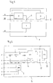
- Fig. 1:
- ein vereinfachtes Blockschaltbild eines Meßgrößenaufnehmers mit einem angeschlossenen Datenspeichermodul;
- Fig. 2:
- ein vereinfachtes Schaltbild des Meßgrößenaufnehmers mit integriertem Datenspeichermodul, und
- Fig. 3:
- eine Fold-Back-Kennlinie zur Strombegrenzung im Kommunikationsmodus.
- Fig. 1:
- a simplified block diagram of a Meßgrößenaufnehmers with a data storage module connected;
- Fig. 2:
- a simplified circuit diagram of Meßgrößenaufnehmers with integrated data storage module, and
- 3:
- a fold-back characteristic for current limitation in communication mode.
In
Das Aufnehmerelement 1 stellt einen physikalisch-elektrischen Wandler dar, der beispielsweise aus einem Dehnungsmeßstreifen besteht, der auf einem Verformungskörper appliziert ist. Derartige Aufnehmerelemente 1 werden als Kraft- oder Druckaufnehmer verwendet, wobei eine Biegespannung am Verformungskörper in eine elektrische Widerstandsänderung umgewandelt wird, aus der in einer Auswertevorrichtung ein Kraft- oder Druckmeßwert ermittelt, angezeigt oder weiterverarbeitet wird. Dazu kann das Aufnehmerelement 1 in einer Dreileitertechnik 11, 12, 13 mit der Auswertevorrichtung verbunden werden, die mittels einer Meßbrückenschaltung das elektrische Meßsignal auswertet.The
Eine derartige Auswerteschaltung, die mit einem Dehnungsmeßstreifenaufnehmerelement über drei Leitungen verbunden wird, ist aus der
Sollen nun zur Auswertung der Meßsignale Aufnehmerkennwerte oder Kalibrierdaten zur Auswertevorrichtung übertragen werden, so wird vom Meßmodus in einen Kommunikationsmodus umgeschaltet. Dazu wird von Seiten der Auswertevorrichtung der Speicherschaltung 3 über das Leitungspaar 11, 12 aus Fühlerleitung 11 und Meß- und Speiseleitung 12 eine Spannung eingeprägt. Da bei der herkömmlichen Dreileiterschaltung die Fühlerleitung 11 und die Speiseleitung 12 vor dem Aufnehmerelement unmittelbar miteinander verbunden sind, würde auf diesen beiden Leitungen ein großer Strom fließen, der lediglich durch die Leitungswiderstände begrenzt würde. Daher wird in das Leitungspaar 11, 12 aus Fühlerleitung 11 und Speiseleitung 12 vor dem Verbindungspunkt 6 am Aufnehmerelement 1 eine elektronische Strombegrenzungsschaltung 2 vorgesehen, die durch eine Fold-Back-Kennlinie den Strom auf einen kleinen Reststrom begrenzt. Damit steht hier die eingeprägte Spannung zur Versorgung der Speicherschaltung 3 zur Verfügung, wodurch diese in den Kommunikationsmodus umschaltet.If transducer characteristics or calibration data are now to be transmitted to the evaluation device for evaluation of the measurement signals, the measurement mode is switched to a communication mode. For this purpose, a voltage is impressed from the side of the evaluation device of the
Für die Übertragung der Daten von der Speicherschaltung 3 zur Auswertevorrichtung wird das Leitungspaar 11, 12 aus Fühlerleitung 11 und Speiseleitung 12 benutzt. Über dieses Leitungspaar 11, 12 wird sowohl die Energie zur Speisung der Speicherschaltung 3 als auch die Information von der Speicherschaltung 3 übertragen. Dazu wird als Speicherschaltung 3 eine integrierte Schaltung des Herstellers Dallas verwendet, die nach einem Dallas-1-wire-Protokoll arbeitet, so daß keine zusätzlichen Leitungen im Kommunikationsmodus benötigt werden. Allerdings können zur Übertragung der Daten zwischen der Auswertevorrichtung und der Speicherschaltung 3 auch weitere für den Meßbetrieb vorgesehene Speise- und Meßleitungen 13 verwendet werden, indem diese durch elektronische Schalteinrichtungen im Aufnehmer 4 von diesem abgetrennt und an die Speicherschaltung 3 angeschaltet werden. Auch bei dieser Ausführung werden für den Kommunikationsmodus keine zusätzlichen Leitungen zwischen dem Meßgrößenaufnehmer 4 und der Auswertevorrichtung benötigt.For the transmission of the data from the
Nach dem Auslesen der Kennwert- und/oder Kalibrierdaten wird von Seiten der Auswerteschaltung wieder in den Meßmodus zurückgeschaltet, in dem die eingeprägte Spannung wieder vom Leitungspaar 11, 12 der Fühler- 11 und Speiseleitung 12 abgeschaltet wird. Bei der Verwendung einer programmierbaren Speicherschaltung 3 die beispielsweise als EPROM ausgebildet ist, kann im Kommunikationsmodus der Speicherinhalt nicht nur ausgelesen, sondern durch die Auswertevorrichtung auch mit neuen Kenn- und/oder Kalibrierwerten beschrieben werden.After reading the characteristic and / or calibration data is switched back from the side of the evaluation circuit in the measurement mode in which the impressed voltage is disconnected again from the
Ist die Strombegrenzungsschaltung 2 wieder in den Meßmodus zurückgeschaltet, so erfolgt die Meßwertermittlung wie bei einer Meßschaltung ohne angeschlossenen Datenspeichermodul 5. Dabei werden im Meßmodus keinerlei besondere Anforderungen an die Signale in den Leitungen 11, 12 gestellt. Es ist lediglich sicherzustellen, daß in das verwendete Fühler-Speiseleitungspaar 11, 12 von Seiten der Auswerteelektronik keine Spannung eingeprägt wird. Dies ist immer dann sichergestellt, wenn eine der beiden Leitungen 11, 12 im Meßmodus als Eingangssignal verschaltet ist. Insbesondere ist dieser Aufnehmer 4 mit angeschlossenem Datenspeichermodul 5 auch für eine Trägerfrequenzspeisung und Strom- und Spannungs-Speisungen mit unterschiedlichen Amplituden geeignet. Durch die Charakteristik der Strombegrenzungsschaltung 2 ist sichergestellt, daß der Meßbetrieb nicht beeinträchtigt wird. Dabei stellt eine gewisse elektrische Impedanz dieser Schaltung 2 im Meßbetrieb kein Problem dar, da diese Schaltung 2 in der Fühlerleitung 11 vorgesehen ist und hier im Meßbetrieb nur vernachlässigbare Stromstärken auftreten.If the current limiting
Der vorbeschriebene Meßgrößenaufnehmer 4 mit dem angeschlossenen Datenspeichermodul 5 besteht aus einem Aufnehmerelement 1 mit einem Dehnungsmeßstreifen, der als Viertelbrücke geschaltet und über zwei Meß- und Speiseleitungen 12, 13 und eine Fühlerleitung 11 mit der Auswertevorrichtung verbunden ist. Dabei sind die restlichen Ergänzungswiderstände der Vollbrücke in der Auswertevorrichtung angeordnet und zu einer Vollbrücke mit dem Aufnehmerelement 1 verschaltet. Bei derartigen Aufnehmerelementen 1 sind auch Vierleiterschaltungen bekannt, bei der neben den Meß- und Speiseleitungen 12, 13 zwei Fühlerleitungen 11 vorgesehen sind, wobei jede den Spannungsabfall auf einer der Meß- und Speiseleitungen 12, 13 ausregelt. Auch für eine derartige Vierleiterschaltung ist der Einsatz des vorbeschriebenen Datenspeichermoduls 5 wie vorstehend beschrieben möglich.The
Bei Dehnungsmeßstreifenaufnehmern sind aber auch Fünf- und Sechsleiterschaltungen bekannt, bei der das Aufnehmerelement 1 aus mehreren Dehnungsmeßstreifen (DMS) besteht, das dann als Halb- oder Vollbrücke geschaltet ist. Auch bei diesen Mehrleiterschaltungen sind neben den Speiseleitungen 12, 13 Fühlerleitungen 11 vorgesehen, so daß dabei immer ein Fühler-Speiseleitunaspaar 11, 12 zur Anschaltung des Datenspeichermoduls 5 verwendet werden kann. Derartige Datenspeichermodule 5 sind aber auch bei induktiven Halbbrückenschaltungen einsetzbar, wie sie bei Meßgrößenaufnehmern vorgesehen sind, die als Wegaufnehmer eingesetzt werden. Weiterhin kann der Meßgrößenaufnehmer 4 auch als Temperaturfühler ausgebildet sein, bei dem die physikalisch-elektrischen Wandlerelemente aus temperaturempfindlichen Widerständen bestehen, die als Wheatstonesche Brücke geschaltet sind. Auch diese Schaltungen erfordern zur Kompensation des Spannungsabfalls auf den Verbindungsleitungen zwischen dem Fühlerelement 1 und der Auswertevorrichtung über Fühlerleitungen 11 die in Verbindung mit einer Speiseleitung zur Anschaltung des Datenspeichermoduls 5 nutzbar sind.In Dehnungsmeßstreifenaufnehmern but also five-and six-wire circuits are known in which the
Derartige Temperaturfühler können aber auch mit einem Thermoelement ausgebildet sein, wobei zwischen der Auswertevorrichtung und dem Thermoelement lediglich ein Leitungspaar benötigt wird. Da bei einem Thermoelement aber nur eine sehr geringe Spannung erzeugt wird, kann am Aufnehmerelement 1 von einem gleichen elektrischen Potential ausgegangen werden, das zur Anschaltung eines Datenspeichermoduls 5 geeignet ist. Der Einsatz der vorbeschriebenen Datenspeichermodulschaltung 5 ist somit für eine Vielzahl von Aufnehmerelementen 1 möglich, so daß damit ein Großteil der heute eingesetzten analogen Meßgrößenaufnehmer ausgerüstet werden kann, die einen räumlichen Abstand zu ihrer Auswertevorrichtung aufweisen und mit auslesbarem Kennwert- und/oder Kalibrierdatenspeichern aus- oder nachgerüstet werden sollen. Insbesondere bei einer digitalen Weiterverarbeitung der Meßsignale in der Auswertevorrichtung ist die selbsttätige Auslesung und/oder Programmierung derartiger Kenn- und/oder Kalibrierwerte von Vorteil.However, such temperature sensors can also be formed with a thermocouple, wherein only one line pair is required between the evaluation device and the thermocouple. Since only a very low voltage is generated in a thermocouple, it can be assumed at the
In
Im Kommunikationsmodus wird nun in das Leitungspaar 2, 2' von Seiten der Auswertevorrichtung eine Spannung von 5 Volt eingeprägt. Der Spannungswandler IC1 erzeugt daraus eine negative Spannung von -5 V, die den Feld-Effekt-Transistor T1 hochohmig schaltet und damit den Strom entsprechend einer Fold-Back-Kennlinie begrenzt. In
Die Speicherschaltung 3 besteht im wesentlichen aus einem integrierten Halbleiterbaustein IC2 der beispielsweise von Hersteller Dallas Semiconductor lieferbar ist und einen Datenaustausch nach dem Dallas-1-wire-Protokoll ermöglicht. Der Halbleiterspeicher IC2 benötigt für die Energieversorgung sowie den Datenaustausch deshalb lediglich ein Leitungspaar und ist somit ebenfalls in das Fühler-Speiseleitungspaar 2, 2' geschaltet. Diese Schaltung arbeitet im Kommunikationsmodus so, wie bereits zu
Claims (15)
- Measurement pick-up with connected data memory, which is connected to an evaluation device by means of at least two connection leads (2', 2; 11, 12), which have the same electrical potential in the measurement operation, wherein data predefined by the evaluation device can be read from the data memory (3) and/or input, characterised in that the data memory (3) is configured as a data memory module (5), which is connected to a pair of leads (2', 2; 11, 12) with the same or approximately the same electrical potential in the measurement mode and can be switched over by an electronic current limiter circuit (2) in the data memory module (5) from the measurement mode into a communication mode for data transfer.
- Measurement pick-up according to claim 1, characterised in that the data memory module (5) includes a current limiter circuit (2) and a data memory (3) for the readout and/or input of predefinable characteristic and/or calibration data.
- Measurement pick-up according to claim 1 or 2, characterised in that there is provided for the physical-electrical conversion at least one pick-up element (1), which forms a structural unit with the data memory module (5) or is arranged in the local vicinity thereof.
- Measurement pick-up according to one of the preceding claims, characterised in that the pick-up element (1) is provided with strain gauges (DMS) or other variable resistances for the physical-electrical conversion, which are connected in the form of a Wheatstone bridge and are connected with three, four, five or six leads (1, 2, 2', 3, 3', 4; 11, 12, 13) to the evaluation device.
- Measurement pick-up according to one of claims 1 to 3, characterised in that the pick-up element (1) is configured as a thermocouple or as an inductive pick-up, which is connected to the evaluation device by means of at least two leads.
- Measurement pick-up according to one of the preceding claims, characterised in that the current limiter circuit (2) is configured such that switchover into a cutoff current limitation according to a fold-back characteristic (7), which represents a communication mode, occurs by means of the evaluation device by an impressed voltage on the pair of leads (2', 2; 11, 12) with the same electrical potential.
- Measurement pick-up according to one of the preceding claims, characterised in that in the communication mode the data stored in the data memory (3) can be read and/or new data can be input by means of the evaluation device.
- Measurement pick-up according to one of the preceding claims, characterised in that the current limiter circuit (2) includes at least one voltage transformer (IC1), a field-effect transistor (T1), a resistance (R1), a diode (D) and a capacitor (C1), which are connected into a sensor lead (2', 11) or voltage-free measuring lead.
- Measurement pick-up according to one of the preceding claims, characterised in that the data memory (3) consists of an integrated circuit (IC2), which is configured such that the data transfer occurs according to the Dallas-1-wire protocol.
- Measurement pick-up according to one of the preceding claims, characterised in that the leads (2, 2', 11, 12) for switchover into the communication mode and for data exchange during the measurement operation are at the same time provided for power supply to the pick-up element (1) and/or for measured value acquisition.
- Measurement pick-up according to one of the preceding claims, characterised in that the measurement pick-up with data memory (3) of three, four, five, and six lead type has the same number of connection leads (1, 2, 2', 3, 3', 4; 11, 12, 13) as a conventional pick-up without a data memory.
- Method for acquiring measured values and exchanging data with a measurement pick-up according to one of claims 1 to 10, characterised in that to switchover from a measurement mode into a communication mode a voltage is impressed on a pair of connection leads (2, 2'; 11, 12) with the same electrical potential between a pick-up (4) and an evaluation device, by means of which the current is limited to a low cutoff current (7) and which is maintained during the data exchange, wherein in the measurement mode the pair of connection leads (2, 2'; 11, 12) serves to supply power and/or transfer measured values.
- Method according to claim 12, characterised in that for switchover into the communication mode and for data transfer, a pair of leads (2, 2'; 11, 12) is used, which is also necessary for measured value acquisition and/or supply in conventional two-, three-, four-, five- or six-conductor circuits for connection of the measurement pick-up (4) and the evaluation circuit.
- Method according to one of claims 12 or 13, characterised in that the measurement pick-up (4) is supplied with a d.c. voltage, direct current, carrier frequency voltage or carrier frequency current.
- Method according to one of claims 12 to 14, characterised in that a plurality of measurement pick-ups (4) are connected in parallel to data memory module (5) and the data of the individual data memory modules (5) are read out by a common evaluation device.
Applications Claiming Priority (3)
| Application Number | Priority Date | Filing Date | Title |
|---|---|---|---|
| DE10130215 | 2001-06-22 | ||
| DE10130215A DE10130215B4 (en) | 2001-06-22 | 2001-06-22 | Measuring sensor with connected data memory |
| PCT/EP2002/006836 WO2003001155A2 (en) | 2001-06-22 | 2002-06-20 | Transducer comprising connected data memory |
Publications (2)
| Publication Number | Publication Date |
|---|---|
| EP1399713A2 EP1399713A2 (en) | 2004-03-24 |
| EP1399713B1 true EP1399713B1 (en) | 2008-02-13 |
Family
ID=7689123
Family Applications (1)
| Application Number | Title | Priority Date | Filing Date |
|---|---|---|---|
| EP02758254A Expired - Lifetime EP1399713B1 (en) | 2001-06-22 | 2002-06-20 | Transducer comprising connected data memory |
Country Status (5)
| Country | Link |
|---|---|
| US (1) | US7016792B2 (en) |
| EP (1) | EP1399713B1 (en) |
| AT (1) | ATE386254T1 (en) |
| DE (2) | DE10130215B4 (en) |
| WO (1) | WO2003001155A2 (en) |
Families Citing this family (10)
| Publication number | Priority date | Publication date | Assignee | Title |
|---|---|---|---|---|
| DE102006001084B4 (en) * | 2006-01-03 | 2009-09-03 | Imc Messsysteme Gmbh | Measured variable detection device and method for detecting measured variables |
| US8010322B2 (en) * | 2006-05-17 | 2011-08-30 | Honeywell International Inc. | Signal conditioning IC with conditioning-coefficient memory |
| US8175835B2 (en) | 2006-05-17 | 2012-05-08 | Honeywell International Inc. | Flow sensor with conditioning-coefficient memory |
| DE102006039295A1 (en) * | 2006-08-22 | 2008-03-13 | Knorr-Bremse Systeme für Nutzfahrzeuge GmbH | Arrangement for operating a sensor |
| ES2375380T3 (en) * | 2007-01-19 | 2012-02-29 | Sick Stegmann Gmbh | PROCEDURE AND DEVICE FOR THE SETTING OF PARAMETERS OF A MEASUREMENT INSTALLATION. |
| DE102007012992B3 (en) * | 2007-03-14 | 2008-08-14 | Imc Messsysteme Gmbh | Measured variable sensor for use in measured variable detection system, has capacitor storage unit laid in connection between connecting cable and sensor line, where connection of inductive component is attached over diode to storage unit |
| DE102008034318B4 (en) * | 2008-07-23 | 2019-08-29 | Robert Bosch Gmbh | Arrangement for evaluating the measured values of a transducer |
| US8718981B2 (en) | 2011-05-09 | 2014-05-06 | Honeywell International Inc. | Modular sensor assembly including removable sensing module |
| DE102012007776B4 (en) | 2012-04-25 | 2014-06-26 | Brüel & Kjaer Vibro GmbH | Single-wire programming and measuring chain |
| DE102012014584A1 (en) | 2012-07-23 | 2014-01-23 | Hottinger Baldwin Messtechnik Gmbh | Measured variable sensor with internal data memory |
Family Cites Families (20)
| Publication number | Priority date | Publication date | Assignee | Title |
|---|---|---|---|---|
| DE2302024C3 (en) | 1973-01-16 | 1978-07-27 | Siemens Ag, 1000 Berlin Und 8000 Muenchen | Circuit arrangement for connecting telegraphy and data subscribers to a switching system |
| DE3446248A1 (en) | 1984-12-19 | 1986-06-19 | Robert Bosch Gmbh, 7000 Stuttgart | SENSOR FOR MEASURING PHYSICAL SIZES AND METHOD FOR ADJUSTING THE SENSOR |
| DE3535642A1 (en) * | 1985-10-05 | 1986-07-03 | Mtu Motoren- Und Turbinen-Union Friedrichshafen Gmbh, 7990 Friedrichshafen | Device for correcting measured values |
| DE3743846A1 (en) * | 1987-12-23 | 1989-07-13 | Porsche Ag | TRANSDUCERS |
| DE4024402C1 (en) * | 1990-08-01 | 1991-10-31 | Dr.Ing.H.C. F. Porsche Ag, 7000 Stuttgart, De | |
| DE4114073C3 (en) * | 1991-04-30 | 2001-07-05 | Bosch Gmbh Robert | Circuit arrangement for stabilizing a voltage |
| DE4114921A1 (en) * | 1991-05-07 | 1992-11-12 | Ahlborn Mess Und Regelungstech | Electrical plug connector with multiple pins - has EEPROM memory that can be programmed with data defining specific configuration being used |
| DE4129577C2 (en) * | 1991-09-06 | 1999-11-25 | Mueller Arnold Gmbh Co Kg | Measuring system for measuring the angle of rotation |
| DE29521356U1 (en) * | 1994-10-12 | 1997-01-02 | Sega Enterprises Kk | Improving communication between a data processing device and its peripheral device |
| WO1997020447A1 (en) * | 1995-11-24 | 1997-06-05 | Prüftechnik Dieter Busch AG | System for the production and processing of measuring signals |
| US5940510A (en) * | 1996-01-31 | 1999-08-17 | Dallas Semiconductor Corporation | Transfer of valuable information between a secure module and another module |
| DE19621375A1 (en) * | 1996-05-28 | 1997-12-04 | Sartorius Gmbh | Electronic scales based on electromagnetic force compensation |
| US5805466A (en) | 1996-11-27 | 1998-09-08 | Motorola Inc. | Device and method for calibrating a signal |
| DE19707708C2 (en) * | 1997-02-26 | 2002-01-10 | Infineon Technologies Ag | Current limiting circuit |
| USRE41847E1 (en) * | 1997-07-14 | 2010-10-19 | Panasonic Corporation | Sensor provided with adjusting function |
| NZ505099A (en) | 1997-11-20 | 2002-03-01 | Weyerhaeuser Co | Nutritive media and manufactured seeds comprising same |
| US6239732B1 (en) * | 1998-04-13 | 2001-05-29 | Dallas Semiconductor Corporation | One-wire device with A-to-D converter |
| DE19856090C1 (en) * | 1998-12-04 | 2000-07-06 | Pcs Process Control Systems Gm | Measuring signal preprocessing device for a programmable logic controller (PLC) |
| DE19957088A1 (en) * | 1999-11-29 | 2001-05-31 | Hbm Mes Und Systemtechnik Gmbh | Three phase measurement bridge circuit with supply current adjustment |
| DE20018871U1 (en) * | 2000-11-04 | 2001-02-01 | Rheintacho Messtechnik Gmbh | Circuit arrangement |
-
2001
- 2001-06-22 DE DE10130215A patent/DE10130215B4/en not_active Expired - Fee Related
-
2002
- 2002-06-20 DE DE50211683T patent/DE50211683D1/en not_active Expired - Lifetime
- 2002-06-20 AT AT02758254T patent/ATE386254T1/en not_active IP Right Cessation
- 2002-06-20 US US10/481,506 patent/US7016792B2/en not_active Expired - Fee Related
- 2002-06-20 EP EP02758254A patent/EP1399713B1/en not_active Expired - Lifetime
- 2002-06-20 WO PCT/EP2002/006836 patent/WO2003001155A2/en active IP Right Grant
Also Published As
| Publication number | Publication date |
|---|---|
| WO2003001155A3 (en) | 2003-12-11 |
| ATE386254T1 (en) | 2008-03-15 |
| DE50211683D1 (en) | 2008-03-27 |
| DE10130215B4 (en) | 2007-08-30 |
| DE10130215A1 (en) | 2003-01-02 |
| EP1399713A2 (en) | 2004-03-24 |
| WO2003001155A2 (en) | 2003-01-03 |
| US7016792B2 (en) | 2006-03-21 |
| US20040204896A1 (en) | 2004-10-14 |
Similar Documents
| Publication | Publication Date | Title |
|---|---|---|
| EP0324067B1 (en) | Measurement pick-off | |
| DE4024402C1 (en) | ||
| EP0892249B1 (en) | Measuring arrangement | |
| EP0883097B1 (en) | Device for transmitting signals between a transmitter and a receiver | |
| EP1733410A1 (en) | System comprising an automotive fuse and an a/d converter | |
| EP1399713B1 (en) | Transducer comprising connected data memory | |
| WO2000050847A1 (en) | Measuring transducer | |
| EP2035900B1 (en) | Method for determining the load impedance of a measuring transducer | |
| DE102008043336A1 (en) | Modular meter with distributed data and algorithms | |
| EP2880410B1 (en) | Multiwire measuring device for detecting a defective, temperature-dependent resistance sensor | |
| DE102018128305B4 (en) | Method for the sensor-side setting of the signal type expected from the signal input of a higher-level control unit of automation technology | |
| EP3729037A1 (en) | Method for providing calibrated pressure transducers | |
| EP0725995B1 (en) | Remote power supply unit | |
| EP3983853B1 (en) | Automation field device | |
| DE102012007776B4 (en) | Single-wire programming and measuring chain | |
| WO2012119829A1 (en) | Measuring device with compensation for a delayed response behavior | |
| EP0677721A1 (en) | Measuring device, in particular for a data acquisition station | |
| EP2048478B1 (en) | Method for recognising a sensor at a measurement amplifier and for automatically adapting a measurement amplifier to a sensor | |
| DE3433760A1 (en) | Microelectronic measured data acquisition system | |
| WO2006051057A1 (en) | Device and method for compensating transducers | |
| DE102018206998A1 (en) | Information setting device and electronic device | |
| DE102013012957A1 (en) | Sensor component and sensor interface | |
| DE102017112755B4 (en) | Current repeater | |
| WO2022258092A1 (en) | Method for installing and operating a measuring assembly with spatially widely distributed sensor measuring points | |
| DE102020133125A1 (en) | Measuring device, measuring system and use of a measuring system |
Legal Events
| Date | Code | Title | Description |
|---|---|---|---|
| PUAI | Public reference made under article 153(3) epc to a published international application that has entered the european phase |
Free format text: ORIGINAL CODE: 0009012 |
|
| 17P | Request for examination filed |
Effective date: 20040116 |
|
| AK | Designated contracting states |
Kind code of ref document: A2 Designated state(s): AT BE CH CY DE DK ES FI FR GB GR IE IT LI LU MC NL PT SE TR |
|
| 17Q | First examination report despatched |
Effective date: 20060913 |
|
| GRAP | Despatch of communication of intention to grant a patent |
Free format text: ORIGINAL CODE: EPIDOSNIGR1 |
|
| GRAS | Grant fee paid |
Free format text: ORIGINAL CODE: EPIDOSNIGR3 |
|
| GRAA | (expected) grant |
Free format text: ORIGINAL CODE: 0009210 |
|
| AK | Designated contracting states |
Kind code of ref document: B1 Designated state(s): AT BE CH CY DE DK ES FI FR GB GR IE IT LI LU MC NL PT SE TR |
|
| REG | Reference to a national code |
Ref country code: GB Ref legal event code: FG4D Free format text: NOT ENGLISH |
|
| REG | Reference to a national code |
Ref country code: CH Ref legal event code: EP |
|
| REG | Reference to a national code |
Ref country code: IE Ref legal event code: FG4D Free format text: LANGUAGE OF EP DOCUMENT: GERMAN |
|
| REF | Corresponds to: |
Ref document number: 50211683 Country of ref document: DE Date of ref document: 20080327 Kind code of ref document: P |
|
| GBT | Gb: translation of ep patent filed (gb section 77(6)(a)/1977) |
Effective date: 20080313 |
|
| PG25 | Lapsed in a contracting state [announced via postgrant information from national office to epo] |
Ref country code: FI Free format text: LAPSE BECAUSE OF FAILURE TO SUBMIT A TRANSLATION OF THE DESCRIPTION OR TO PAY THE FEE WITHIN THE PRESCRIBED TIME-LIMIT Effective date: 20080213 Ref country code: ES Free format text: LAPSE BECAUSE OF FAILURE TO SUBMIT A TRANSLATION OF THE DESCRIPTION OR TO PAY THE FEE WITHIN THE PRESCRIBED TIME-LIMIT Effective date: 20080524 |
|
| NLV1 | Nl: lapsed or annulled due to failure to fulfill the requirements of art. 29p and 29m of the patents act | ||
| ET | Fr: translation filed | ||
| REG | Reference to a national code |
Ref country code: IE Ref legal event code: FD4D |
|
| PG25 | Lapsed in a contracting state [announced via postgrant information from national office to epo] |
Ref country code: IE Free format text: LAPSE BECAUSE OF FAILURE TO SUBMIT A TRANSLATION OF THE DESCRIPTION OR TO PAY THE FEE WITHIN THE PRESCRIBED TIME-LIMIT Effective date: 20080213 Ref country code: NL Free format text: LAPSE BECAUSE OF FAILURE TO SUBMIT A TRANSLATION OF THE DESCRIPTION OR TO PAY THE FEE WITHIN THE PRESCRIBED TIME-LIMIT Effective date: 20080213 Ref country code: SE Free format text: LAPSE BECAUSE OF FAILURE TO SUBMIT A TRANSLATION OF THE DESCRIPTION OR TO PAY THE FEE WITHIN THE PRESCRIBED TIME-LIMIT Effective date: 20080513 Ref country code: PT Free format text: LAPSE BECAUSE OF FAILURE TO SUBMIT A TRANSLATION OF THE DESCRIPTION OR TO PAY THE FEE WITHIN THE PRESCRIBED TIME-LIMIT Effective date: 20080714 Ref country code: DK Free format text: LAPSE BECAUSE OF FAILURE TO SUBMIT A TRANSLATION OF THE DESCRIPTION OR TO PAY THE FEE WITHIN THE PRESCRIBED TIME-LIMIT Effective date: 20080213 |
|
| PLBE | No opposition filed within time limit |
Free format text: ORIGINAL CODE: 0009261 |
|
| STAA | Information on the status of an ep patent application or granted ep patent |
Free format text: STATUS: NO OPPOSITION FILED WITHIN TIME LIMIT |
|
| BERE | Be: lapsed |
Owner name: HOTTINGER BALDWIN MESSTECHNIK G.M.B.H. Effective date: 20080630 |
|
| 26N | No opposition filed |
Effective date: 20081114 |
|
| PG25 | Lapsed in a contracting state [announced via postgrant information from national office to epo] |
Ref country code: MC Free format text: LAPSE BECAUSE OF NON-PAYMENT OF DUE FEES Effective date: 20080630 |
|
| REG | Reference to a national code |
Ref country code: CH Ref legal event code: PL |
|
| PG25 | Lapsed in a contracting state [announced via postgrant information from national office to epo] |
Ref country code: BE Free format text: LAPSE BECAUSE OF NON-PAYMENT OF DUE FEES Effective date: 20080630 |
|
| PG25 | Lapsed in a contracting state [announced via postgrant information from national office to epo] |
Ref country code: LI Free format text: LAPSE BECAUSE OF NON-PAYMENT OF DUE FEES Effective date: 20080630 Ref country code: CH Free format text: LAPSE BECAUSE OF NON-PAYMENT OF DUE FEES Effective date: 20080630 |
|
| PG25 | Lapsed in a contracting state [announced via postgrant information from national office to epo] |
Ref country code: CY Free format text: LAPSE BECAUSE OF FAILURE TO SUBMIT A TRANSLATION OF THE DESCRIPTION OR TO PAY THE FEE WITHIN THE PRESCRIBED TIME-LIMIT Effective date: 20080213 |
|
| PG25 | Lapsed in a contracting state [announced via postgrant information from national office to epo] |
Ref country code: IT Free format text: LAPSE BECAUSE OF FAILURE TO SUBMIT A TRANSLATION OF THE DESCRIPTION OR TO PAY THE FEE WITHIN THE PRESCRIBED TIME-LIMIT Effective date: 20080213 Ref country code: AT Free format text: LAPSE BECAUSE OF NON-PAYMENT OF DUE FEES Effective date: 20080620 |
|
| PG25 | Lapsed in a contracting state [announced via postgrant information from national office to epo] |
Ref country code: LU Free format text: LAPSE BECAUSE OF NON-PAYMENT OF DUE FEES Effective date: 20080620 |
|
| PG25 | Lapsed in a contracting state [announced via postgrant information from national office to epo] |
Ref country code: TR Free format text: LAPSE BECAUSE OF FAILURE TO SUBMIT A TRANSLATION OF THE DESCRIPTION OR TO PAY THE FEE WITHIN THE PRESCRIBED TIME-LIMIT Effective date: 20080213 |
|
| PG25 | Lapsed in a contracting state [announced via postgrant information from national office to epo] |
Ref country code: GR Free format text: LAPSE BECAUSE OF FAILURE TO SUBMIT A TRANSLATION OF THE DESCRIPTION OR TO PAY THE FEE WITHIN THE PRESCRIBED TIME-LIMIT Effective date: 20080514 |
|
| REG | Reference to a national code |
Ref country code: DE Ref legal event code: R082 Ref document number: 50211683 Country of ref document: DE Representative=s name: SCHWEIZER, JOACHIM, DIPL.-ING., DE |
|
| REG | Reference to a national code |
Ref country code: FR Ref legal event code: PLFP Year of fee payment: 15 |
|
| REG | Reference to a national code |
Ref country code: FR Ref legal event code: PLFP Year of fee payment: 16 |
|
| REG | Reference to a national code |
Ref country code: FR Ref legal event code: PLFP Year of fee payment: 17 |
|
| PGFP | Annual fee paid to national office [announced via postgrant information from national office to epo] |
Ref country code: FR Payment date: 20190626 Year of fee payment: 18 |
|
| PGFP | Annual fee paid to national office [announced via postgrant information from national office to epo] |
Ref country code: DE Payment date: 20190624 Year of fee payment: 18 Ref country code: GB Payment date: 20190624 Year of fee payment: 18 |
|
| REG | Reference to a national code |
Ref country code: DE Ref legal event code: R082 Ref document number: 50211683 Country of ref document: DE Representative=s name: SCHWEIZER, JOACHIM, DIPL.-ING., DE Ref country code: DE Ref legal event code: R081 Ref document number: 50211683 Country of ref document: DE Owner name: HOTTINGER BRUEEL & KJAER GMBH, DE Free format text: FORMER OWNER: HOTTINGER BALDWIN MESSTECHNIK GMBH, 64293 DARMSTADT, DE |
|
| REG | Reference to a national code |
Ref country code: DE Ref legal event code: R119 Ref document number: 50211683 Country of ref document: DE |
|
| GBPC | Gb: european patent ceased through non-payment of renewal fee |
Effective date: 20200620 |
|
| PG25 | Lapsed in a contracting state [announced via postgrant information from national office to epo] |
Ref country code: GB Free format text: LAPSE BECAUSE OF NON-PAYMENT OF DUE FEES Effective date: 20200620 Ref country code: FR Free format text: LAPSE BECAUSE OF NON-PAYMENT OF DUE FEES Effective date: 20200630 |
|
| PG25 | Lapsed in a contracting state [announced via postgrant information from national office to epo] |
Ref country code: DE Free format text: LAPSE BECAUSE OF NON-PAYMENT OF DUE FEES Effective date: 20210101 |