EP1399641B1 - Rohrzentriervorrichtung und verfahren zur befestigung - Google Patents
Rohrzentriervorrichtung und verfahren zur befestigung Download PDFInfo
- Publication number
- EP1399641B1 EP1399641B1 EP02729745A EP02729745A EP1399641B1 EP 1399641 B1 EP1399641 B1 EP 1399641B1 EP 02729745 A EP02729745 A EP 02729745A EP 02729745 A EP02729745 A EP 02729745A EP 1399641 B1 EP1399641 B1 EP 1399641B1
- Authority
- EP
- European Patent Office
- Prior art keywords
- centralizer
- pipe
- tubular section
- casing
- metal pipe
- Prior art date
- Legal status (The legal status is an assumption and is not a legal conclusion. Google has not performed a legal analysis and makes no representation as to the accuracy of the status listed.)
- Expired - Lifetime
Links
- 238000000034 method Methods 0.000 title claims abstract description 25
- 238000002788 crimping Methods 0.000 claims description 29
- 239000002184 metal Substances 0.000 claims description 23
- 238000003780 insertion Methods 0.000 claims description 4
- 230000037431 insertion Effects 0.000 claims description 4
- 238000005553 drilling Methods 0.000 abstract description 20
- 238000009434 installation Methods 0.000 abstract description 5
- 238000006073 displacement reaction Methods 0.000 description 17
- 239000000463 material Substances 0.000 description 11
- 230000001965 increasing effect Effects 0.000 description 4
- 230000003466 anti-cipated effect Effects 0.000 description 2
- 238000001816 cooling Methods 0.000 description 2
- 230000000694 effects Effects 0.000 description 2
- 238000010438 heat treatment Methods 0.000 description 2
- 238000010297 mechanical methods and process Methods 0.000 description 2
- 229910000975 Carbon steel Inorganic materials 0.000 description 1
- 239000004593 Epoxy Substances 0.000 description 1
- 229910000831 Steel Inorganic materials 0.000 description 1
- 230000009471 action Effects 0.000 description 1
- 230000003190 augmentative effect Effects 0.000 description 1
- 238000005422 blasting Methods 0.000 description 1
- 239000010962 carbon steel Substances 0.000 description 1
- 238000005266 casting Methods 0.000 description 1
- 230000008859 change Effects 0.000 description 1
- 238000006243 chemical reaction Methods 0.000 description 1
- 238000010276 construction Methods 0.000 description 1
- 230000001419 dependent effect Effects 0.000 description 1
- 238000005516 engineering process Methods 0.000 description 1
- 230000002708 enhancing effect Effects 0.000 description 1
- 239000003292 glue Substances 0.000 description 1
- 230000007246 mechanism Effects 0.000 description 1
- 238000003801 milling Methods 0.000 description 1
- 239000000203 mixture Substances 0.000 description 1
- 239000003208 petroleum Substances 0.000 description 1
- 230000008569 process Effects 0.000 description 1
- 230000001012 protector Effects 0.000 description 1
- 238000007788 roughening Methods 0.000 description 1
- 239000007787 solid Substances 0.000 description 1
- 239000010959 steel Substances 0.000 description 1
- 238000003466 welding Methods 0.000 description 1
Images
Classifications
-
- E—FIXED CONSTRUCTIONS
- E21—EARTH OR ROCK DRILLING; MINING
- E21B—EARTH OR ROCK DRILLING; OBTAINING OIL, GAS, WATER, SOLUBLE OR MELTABLE MATERIALS OR A SLURRY OF MINERALS FROM WELLS
- E21B17/00—Drilling rods or pipes; Flexible drill strings; Kellies; Drill collars; Sucker rods; Cables; Casings; Tubings
- E21B17/10—Wear protectors; Centralising devices, e.g. stabilisers
- E21B17/1078—Stabilisers or centralisers for casing, tubing or drill pipes
-
- E—FIXED CONSTRUCTIONS
- E21—EARTH OR ROCK DRILLING; MINING
- E21B—EARTH OR ROCK DRILLING; OBTAINING OIL, GAS, WATER, SOLUBLE OR MELTABLE MATERIALS OR A SLURRY OF MINERALS FROM WELLS
- E21B29/00—Cutting or destroying pipes, packers, plugs or wire lines, located in boreholes or wells, e.g. cutting of damaged pipes, of windows; Deforming of pipes in boreholes or wells; Reconditioning of well casings while in the ground
-
- E—FIXED CONSTRUCTIONS
- E21—EARTH OR ROCK DRILLING; MINING
- E21B—EARTH OR ROCK DRILLING; OBTAINING OIL, GAS, WATER, SOLUBLE OR MELTABLE MATERIALS OR A SLURRY OF MINERALS FROM WELLS
- E21B43/00—Methods or apparatus for obtaining oil, gas, water, soluble or meltable materials or a slurry of minerals from wells
- E21B43/02—Subsoil filtering
- E21B43/10—Setting of casings, screens, liners or the like in wells
-
- E—FIXED CONSTRUCTIONS
- E21—EARTH OR ROCK DRILLING; MINING
- E21B—EARTH OR ROCK DRILLING; OBTAINING OIL, GAS, WATER, SOLUBLE OR MELTABLE MATERIALS OR A SLURRY OF MINERALS FROM WELLS
- E21B7/00—Special methods or apparatus for drilling
- E21B7/20—Driving or forcing casings or pipes into boreholes, e.g. sinking; Simultaneously drilling and casing boreholes
-
- Y—GENERAL TAGGING OF NEW TECHNOLOGICAL DEVELOPMENTS; GENERAL TAGGING OF CROSS-SECTIONAL TECHNOLOGIES SPANNING OVER SEVERAL SECTIONS OF THE IPC; TECHNICAL SUBJECTS COVERED BY FORMER USPC CROSS-REFERENCE ART COLLECTIONS [XRACs] AND DIGESTS
- Y10—TECHNICAL SUBJECTS COVERED BY FORMER USPC
- Y10T—TECHNICAL SUBJECTS COVERED BY FORMER US CLASSIFICATION
- Y10T29/00—Metal working
- Y10T29/49—Method of mechanical manufacture
- Y10T29/49826—Assembling or joining
- Y10T29/49908—Joining by deforming
Definitions
- the present invention relates to centralizers attached to pipe placed in boreholes.
- the invention discloses centralizers and methods of attachment to enable transfer of structurally significant axial and torsional loads between the centralizer and pipe.
- wells are typically constructed by drilling the well bore using one tubular string, largely comprised of drill pipe, then removing the drill pipe string and completing by installing a second tubular string, referred to as casing, which is subsequently permanently cemented in place.
- casing a tubular string
- centralizers used for casing are not typically required to withstand significant rotation, are typically optimized to improve cementing quality and are only used once. These requirements have led to casing centralizers that attached to the exterior of the connection by means having little or no torsional and limited axial load transfer capacity. As a single use item, they are constructed for lowest cost not durability. With this historic method of well construction, both the drill pipe and casing centralizer designs are separately optimised for the different performance requirements of the drilling and completion operations respectively.
- casing centralizers typically rotate relative to the casing body under application of extended rotation required for drilling, causing wear of the centralizer, casing or both, leading to potential failure of the centralizer or casing.
- Adapting the integral centralizer architecture employed for drill string centralizers, while providing a technically feasible means to centralize casing for drilling, is costly and more complex to implement than simply attaching to the casing exterior. What is required are inexpensive casing centralizers that are rugged, comparatively easy to attach to the casing and able to withstand drilling rotation sufficient to complete at least one well.
- a crimped centralizer has been invented for installation on metal pipe, such as would be useful in well bore drilling and casing operations.
- the present invention provides a centralizer having a cylindrical body which when coaxially placed over a metal pipe and substantially radially inwardly displaced at a plurality of points (i.e. crimped) about the circumference of a section of the cylindrical body, attaches to the pipe to create a connection having structurally significant axial and torque load transfer capacity.
- the load transfer capacity of the connection between the centralizer and the pipe can be arranged to substantially prevent significant relative movement of the centralizer on the pipe under loads that may be encountered when using one or more of the pipes as components of a tubular string used for drilling or completing well bores.
- the pipe on which the centralizer of the present invention is installed must be capable of accepting the hoop stresses of crimping without becoming unstable, for example, without buckling or crumpling. This generally requires that the pipe be thick-walled, for example, having an external diameter to thickness ratio ("D/t") less than 100 and preferably less than 50.
- D/t external diameter to thickness ratio
- the centralizer should be amenable to rapid field installation on joints of pipe having at least one non-upset end.
- the centralizer, once installed should not substantially reduce the minimum diameter (drift diameter) through the pipe.
- a wellbore casing centralizer comprising: a body having a first end and a second end opposite the first end, an outer facing surface and an inner bore extending therethrough from the first end to the second end sufficiently large to allow insertion therethrough of a selected pipe having an external diameter and a centralizing section on the body including a plurality of bearing surfaces extending outwardly from the outer facing surface, characterized in that: the wellbore casing centralizer further comprises at least one crimpable tubular section on the body and the portion of the inner bore extending through the tubular section having an internal diameter capable of loosely fitting about the external diameter of the pipe.
- the tubular section can be cylindrical or largely cylindrical with some radial variations to the internal diameter or outer surface.
- the tubular section should be circumferentially continuous such that a hoop stress can be set up by radially inwardly displacement (i.e. crimping) at a plurality of points about the circumference of the outer surface of the section.
- the tubular section should be capable of accepting the hoop stresses of crimping without becoming unstable, for example, without buckling or crumpling. This generally requires that the section be thick-walled, for example, having an external diameter to thickness ratio ("D/t") less than 100 and preferably less than 50.
- D/t external diameter to thickness ratio
- the loose fit of the section about the pipe must be sufficient to accommodate the variations of the outer diameter of the pipe intended to be used.
- the bearing surfaces can be for example ribs, lines of weldments etc.
- a method for attaching a centralizer to a metal pipe by crimping comprising the steps of: providing a metal pipe; providing a centralizer having a body with an inner bore therethrough sufficiently large to allow insertion therethrough of the metal pipe and a plurality of outward facing bearing surfaces on the body; and inserting the metal pipe through the inner bore of the centralizer, characterized in that the method further comprises the steps of: the centralizer including at least one crimpable tubular section on the body and having an internal diameter capable of fitting about the outer surface of the metal pipe; applying an inward, substantially radially-directed force to a plurality of points about an outer circumference of the tubular section causing it to plastically deform inwardly and come into contact with the outer surface of the pipe at points corresponding to the plurality of points; and applying such additional inward, substantially radially directed force as required to force both the centralizer and the outer surface of the pipe to displace inwardly an
- the inward, substantially radially directed force is not so great that the drift diameter of the pipe is excessively reduced.
- Frictional forces enabled by the interference fit at the inwardly displaced section provide the mechanism by which structurally significant axial and torsional load may be transferred between the centralizer and pipe without slippage therebetween.
- differential temperature may be used to control interference according to the well known methods of shrink fitting , whereby the differential temperature is obtained by heating the centralizer, cooling the metal pipe, or both, prior to crimping.
- An additional purpose of the present invention is, therefore, to provide a method of obtaining sufficient interference in the crimped connection through purely mechanical means, without requiring a significant temperature differential between the centralizer and metal pipe at the time of crimping.
- This purpose is realized by selecting the elastic limit of the centralizer material, in the section to be crimped, to be less than that of the pipe on which the centralizer is to be installed.
- the elastic limit generally refers to the strain at which the metal of the parts yields.
- a further purpose of the present invention is to facilitate the frictional engagement of the crimped centralizer to the thick-wall pipe.
- the inside surface of centralizer, at least over the section to be crimped is provided with a roughened surface finish.
- a friction enhancing material such as a grit epoxy mixture is disposed in the interfacial region of the crimped section.
- various bonding materials may be disposed in the interfacial region prior to crimping to act as glues augmenting the frictional aspects of the connection once their shear strength is developed after setting.
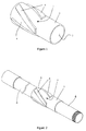
- a centralizer is provided as shown in Figure 1, and a method of crimping it to a thick-wall metal pipe when placed on the pipe as shown in Figure 2.
- the centralizer is provided having a metal body 1 containing an internal bore 2, a cylindrical end 3 forming a section suitable for crimping, and a centralizing section 4 on which ribs 5 are placed.
- the cylindrical end and the centralizing section are formed integral on the body and the internal bore passes through both of them. While the crimpable section in the illustrated embodiment is cylindrical end, it is to be noted that the crimpable section can be formed intermediate a pair of centralizing sections, if desired, rather than on an end. Also, it is to be noted that more than one crimpable section and more than one centralizing section can be provided on the centralizer, as desired.
- Ribs 5 are evenly spaced around the centralizing section. There are at least three ribs spaced about the circumference of the centralizing section. Preferably, each rib is helically shaped and the number, length and pitch of the rib helixes are arranged to ensure the starting circumferential position of each rib overlaps the ending circumferential position of at least one adjacent rib.
- the ribs may be placed on the centralizer body by a variety of methods including milling, casting, welding or hydroforming.
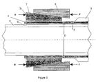
- the internal bore 2 of the centralizer body is selected to loosely fit over at least one end of a thick-wall metal pipe 6, shown as a threaded and coupled casing joint in Figure 2. As shown, this allows the centralizer to be readily inserted over an end of the pipe 6 and placed somewhere along the length of the pipe joint prior to crimping.
- the crimping method of the present invention in its preferred embodiment provides a means to obtain a significant interference fit after crimping even where the centralizer and casing material are at similar temperatures prior to crimping.
- the centralizer is preferably selected to have a thermal expansion coefficient that is equal to or less than that of the casing. Similarly in applications where cooling subsequent to crimping is anticipated, the opposite relationship between thermal expansion coefficients is preferred.
- Radial displacement required to crimp the centralizer cylindrical end 3 to the casing joint 6, on which it is placed may be accomplished by various methods, however a fixture employing a tapered 'collet in housing' architecture was found to work well in practice.
- This well known method of applying uniform radial displacement, and consequently radial force when in contact with the exterior of a cylindrical work piece surface employs a device as shown schematically in Figure 3.
- the device retains the externally tapered fingers or jaws 7 of a collet (segments of an externally conical sleeve) inside a matching internally tapered solid housing 8.
- axial setting force to the housing 8 as shown by vector F, which is reacted at the face 7a of the collet jaws 7, as shown by vector R, tends to induce the collet jaws 7 to penetrate into the collet housing 8 along the angle of its conical bore.
- This causes the jaws 7 to move radially inwardly and engage the work piece to be gripped, in the present case, shown as the cylindrical end 3 of a centralizer.
- the action of the collet may be described in terms of setting displacement, understood as axial displacement of the collet housing 8 with respect to the collet jaws 7.
- the setting force is understood to arise correlative with the setting displacement.
- the axial force F and reaction R are readily applied by, for example, a hollow bore hydraulic actuator (not shown), arranged with an internal bore greater than the casing 6 outside diameter.
- the jaws may be forced inward to first cause sufficient radial displacement to plastically deform the centralizer cylindrical end 3 and bring it into contact with the casing 6.
- This amount of radial displacement removes the annular clearance of the loose fit initially required for placing and positioning the centralizer on the casing 6.
- Application of additional setting force then forces both the centralizer cylindrical end 3, and the underlying wall of the casing 6, inward.
- the setting displacement is preferably applied until the hoop strain in the casing wall at the crimp location equals or slightly exceeds its elastic limit. It will be apparent to one skilled in the art that radial displacement beyond this point will cause little increase in residual interference but will have the undesirable effect of reducing the drift diameter of the casing joint 6.
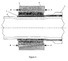
- Figure 4 schematically shows the collet, centralizer and casing as they might appear in the fully crimped position. After the desired radial displacement is achieved, the setting displacement of the collet is reversed which releases it from the centralizer allowing the collet to be removed, leaving the centralizer crimped to the casing.
- the centralizer material at the cylindrical end 3 has an elastic limit less than that of the casing 6.
- the centralizer and casing material are both made from carbon steel having nearly the same elastic modulii. Therefore, the elastic limit may be expressed in terms of yield strength, since elastic limit is generally given by yield stress divided by elastic modulus.
- the required torque to induce sliding rotation of the centralizer relative to the casing would be 5833 ftlb. This may be compared to the maximum expected total drilling torque for this size of casing, which is in the order of 20,000ftlb. Given this crimped centralizer configuration, the torque transferred between just one such centralizer and casing, would need to exceed 25% of the total worst case drilling torque, to induce slippage of the centralizer on the casing.
- the length of the section crimped will in general linearly affect the load transfer capacity of the crimped connection.
- the length of section suitable for crimping, provided by the cylindrical end 3 may be extended almost without limit.
- the length of the collet jaws 7, do not limit length that may be crimped.
- the collet tool may be used to apply the required radial displacement at multiple axial locations to incrementally crimp an extended length cylindrical end 3. Increased load transfer capacity may thus be readily achieved by increasing the crimped section length.
Landscapes
- Engineering & Computer Science (AREA)
- Geology (AREA)
- Life Sciences & Earth Sciences (AREA)
- Mining & Mineral Resources (AREA)
- Environmental & Geological Engineering (AREA)
- Fluid Mechanics (AREA)
- Physics & Mathematics (AREA)
- General Life Sciences & Earth Sciences (AREA)
- Geochemistry & Mineralogy (AREA)
- Mechanical Engineering (AREA)
- Earth Drilling (AREA)
- Lining Or Joining Of Plastics Or The Like (AREA)
- Automatic Assembly (AREA)
Claims (6)
- Bohrlochfutterrohr-Zentriervorrichtung, umfassend: einen Körper (1) mit einem ersten Ende und einem zweiten Ende gegenüber dem ersten Ende, einer nach außen weisenden Fläche und einer inneren Bohrung (2), die sich von dem ersten Ende zu dem zweiten Ende durch denselben erstreckt und ausreichend groß ist, um das Einsetzen eines ausgewählten Rohrs (6) durch dieselbe zu gestatten, welches einen Außendurchmesser aufweist, und einen Zentrier-Abschnitt (4) an dem Körper, der eine Vielzahl von Lagerflächen (5) umfasst, die sich von der nach außen weisenden Fläche nach außen erstrecken, dadurch gekennzeichnet, dass die Bohrlochfutterrohr-Zentriervorrichtung des Weiteren zumindest einen verpressbaren rohrförmigen Abschnitt (3) an dem Körper und dem Teilbereich der inneren Bohrung umfasst, welche sich durch den rohrförmigen Abschnitt erstreckt, mit einem Innendurchmesser, der in der Lage ist, locker um den Außendurchmesser des Rohrs herum zu passen.
- Bohrlochfutterrohr-Zentriervorrichtung nach Anspruch 1, wobei der verpressbare rohrförmige Abschnitt (3) ein Verhältnis von Außendurchmesser zu Dicke von weniger als 100 aufweist.
- Bohrlochfutterrohr-Zentriervorrichtung nach Anspruch 1, wobei der verpressbare rohrförmige Abschnitt (3) ein Verhältnis von Außendurchmesser zu Dicke von weniger als 50 aufweist.
- Bohrlochfutterrohr-Zentriervorrichtung nach Anspruch 1, wobei der verpressbare rohrförmige Abschnitt (3) in Umfangsrichtung kontinuierlich verläuft, so dass darin Umfangsspannung erzeugt werden kann.
- Verfahren zum Befestigen einer Zentriervorrichtung an einem Metallrohr durch Verpressen, wobei das Metallrohr eine Außenfläche aufweist, wobei das Verfahren die Schritte umfasst, dass: ein Metallrohr (6) vorgesehen wird; eine Zentriervorrichtung vorgesehen wird, welche einen Körper (1) mit einer inneren Bohrung (2) durch denselben, die ausreichend groß ist, um das Einsetzen des Metallrohrs durch dieselbe zu gestatten, und eine Vielzahl von nach außen weisenden Lagerflächen (5) an dem Körper aufweist; und das Metallrohr durch die innere Bohrung (2) der Zentriervorrichtung eingesetzt wird, dadurch gekennzeichnet, dass das Verfahren des Weiteren die Schritte umfasst, dass: die Zentriervorrichtung zumindest einen verpressbaren rohrförmigen Abschnitt (3) an dem Körper umfasst und einen Innendurchmesser aufweist, der in der Lage ist, um die Außenfläche des Metallrohrs herum zu passen; eine nach innen, im Wesentlichen radial gerichtete Kraft auf eine Vielzahl von Punkten um einen äußeren Umfang des rohrförmigen Abschnitts (3) herum ausgeübt wird, welche diesen veranlasst, sich plastisch nach innen zu verformen und mit der Außenfläche des Rohrs (6) an Punkten, welche der Vielzahl von Punkten entsprechen, in Kontakt zu kommen; und eine solche zusätzliche nach innen, im Wesentlichen radial gerichtete Kraft ausgeübt wird, die erforderlich ist, um sowohl die Zentriervorrichtung als auch die Außenfläche des Rohrs zu einer Verlagerung nach innen um einen Betrag zu zwingen, der zumindest groß genug ist, damit nach dem Loslassen eine Presspassung zwischen der Zentriervorrichtung und dem Rohr geschaffen wird.
- Verfahren nach Anspruch 5, wobei von der Außenfläche des Rohrs (6) und einer Innenfläche des rohrförmigen Abschnitts (3) zumindest eine aufgerauht wird, um einen Reibungsschluss zwischen denselben zu erleichtern.
Applications Claiming Priority (3)
| Application Number | Priority Date | Filing Date | Title |
|---|---|---|---|
| CA2350681 | 2001-06-15 | ||
| CA002350681A CA2350681A1 (en) | 2001-06-15 | 2001-06-15 | Pipe centralizer and method of attachment |
| PCT/CA2002/000883 WO2002103154A1 (en) | 2001-06-15 | 2002-06-13 | Pipe centralizer and method of attachment |
Publications (2)
| Publication Number | Publication Date |
|---|---|
| EP1399641A1 EP1399641A1 (de) | 2004-03-24 |
| EP1399641B1 true EP1399641B1 (de) | 2007-02-21 |
Family
ID=4169285
Family Applications (1)
| Application Number | Title | Priority Date | Filing Date |
|---|---|---|---|
| EP02729745A Expired - Lifetime EP1399641B1 (de) | 2001-06-15 | 2002-06-13 | Rohrzentriervorrichtung und verfahren zur befestigung |
Country Status (7)
| Country | Link |
|---|---|
| US (1) | US7082997B2 (de) |
| EP (1) | EP1399641B1 (de) |
| AT (1) | ATE354717T1 (de) |
| CA (1) | CA2350681A1 (de) |
| DE (1) | DE60218308T2 (de) |
| DK (1) | DK1399641T3 (de) |
| WO (1) | WO2002103154A1 (de) |
Families Citing this family (46)
| Publication number | Priority date | Publication date | Assignee | Title |
|---|---|---|---|---|
| US7040420B2 (en) | 1994-10-14 | 2006-05-09 | Weatherford/Lamb, Inc. | Methods and apparatus for cementing drill strings in place for one pass drilling and completion of oil and gas wells |
| US7311148B2 (en) | 1999-02-25 | 2007-12-25 | Weatherford/Lamb, Inc. | Methods and apparatus for wellbore construction and completion |
| US7334650B2 (en) | 2000-04-13 | 2008-02-26 | Weatherford/Lamb, Inc. | Apparatus and methods for drilling a wellbore using casing |
| CA2353249A1 (en) | 2001-07-18 | 2003-01-18 | Maurice William Slack | Pipe centralizer and method of attachment |
| DK1399644T3 (da) * | 2001-06-15 | 2007-08-13 | Tesco Corp | Fremgangsmåde til at klargöre en borehulsforing til installation |
| US7730965B2 (en) * | 2002-12-13 | 2010-06-08 | Weatherford/Lamb, Inc. | Retractable joint and cementing shoe for use in completing a wellbore |
| US7303022B2 (en) | 2002-10-11 | 2007-12-04 | Weatherford/Lamb, Inc. | Wired casing |
| US7938201B2 (en) | 2002-12-13 | 2011-05-10 | Weatherford/Lamb, Inc. | Deep water drilling with casing |
| USRE42877E1 (en) | 2003-02-07 | 2011-11-01 | Weatherford/Lamb, Inc. | Methods and apparatus for wellbore construction and completion |
| CA2683763C (en) | 2003-03-05 | 2013-01-29 | Weatherford/Lamb, Inc. | Full bore lined wellbores |
| GB2416360B (en) | 2003-03-05 | 2007-08-22 | Weatherford Lamb | Drilling with casing latch |
| US20090258250A1 (en) * | 2003-04-21 | 2009-10-15 | ATT Technology, Ltd. d/b/a Amco Technology Trust, Ltd. | Balanced Composition Hardfacing Alloy |
| US7361411B2 (en) * | 2003-04-21 | 2008-04-22 | Att Technology, Ltd. | Hardfacing alloy, methods, and products |
| US7264067B2 (en) | 2003-10-03 | 2007-09-04 | Weatherford/Lamb, Inc. | Method of drilling and completing multiple wellbores inside a single caisson |
| US20070209839A1 (en) * | 2006-03-08 | 2007-09-13 | ATT Technology Trust, Ltd. d/b/a Arnco Technology Trust, Ltd. | System and method for reducing wear in drill pipe sections |
| CA2651966C (en) | 2006-05-12 | 2011-08-23 | Weatherford/Lamb, Inc. | Stage cementing methods used in casing while drilling |
| US8276689B2 (en) | 2006-05-22 | 2012-10-02 | Weatherford/Lamb, Inc. | Methods and apparatus for drilling with casing |
| US7854257B2 (en) * | 2007-02-15 | 2010-12-21 | Baker Hughes Incorporated | Mechanically coupled screen and method |
| GB2482456A (en) * | 2009-05-01 | 2012-02-01 | Baker Hughes Inc | Casing bits,drilling assemblies,and methods for use in forming wellbores with expandable casing |
| US8668007B2 (en) * | 2009-11-13 | 2014-03-11 | Wwt International, Inc. | Non-rotating casing centralizer |
| US8245789B2 (en) * | 2010-06-23 | 2012-08-21 | Halliburton Energy Service, Inc. | Apparatus and method for fluidically coupling tubular sections and tubular system formed thereby |
| US8701785B2 (en) | 2011-01-12 | 2014-04-22 | Tesco Corporation | Shrinkable sleeve stabilizer |
| US9982496B2 (en) | 2011-07-26 | 2018-05-29 | Innovex Downhole Solutions, Inc. | Rolled tubular centralizer |
| EP2747860B1 (de) | 2011-08-26 | 2020-06-17 | Waters Technologies Corporation | Flüssigchromatografieleitungsanordnungen mit hochdruckdichtungen |
| USD674818S1 (en) | 2011-10-28 | 2013-01-22 | Top-Co Cementing Products Inc. | Casing centralizer |
| USD665824S1 (en) | 2011-10-28 | 2012-08-21 | Top-Co Cementing Products Inc. | Casing centralizer |
| USD665825S1 (en) | 2011-10-28 | 2012-08-21 | Top-Co Cementing Products Inc. | Casing centralizer |
| USD674817S1 (en) | 2011-10-28 | 2013-01-22 | Top-Co Cementing Products Inc. | Casing centralizer |
| USD664568S1 (en) | 2011-10-28 | 2012-07-31 | Top-Co Cementing Products, Inc. | Casing centralizer |
| GB201202640D0 (en) * | 2012-02-16 | 2012-04-04 | Simpson Neil A A | Swaged friction reducing collar |
| USD849800S1 (en) | 2012-04-04 | 2019-05-28 | Summit Energy Services, Inc. | Casing centralizer having spiral blades |
| USD676464S1 (en) * | 2012-04-04 | 2013-02-19 | Mitchel D. Hansen | Casing centralizer having straight blades |
| US9982490B2 (en) | 2013-03-01 | 2018-05-29 | Baker Hughes Incorporated | Methods of attaching cutting elements to casing bits and related structures |
| US9725967B2 (en) | 2013-07-24 | 2017-08-08 | Bp Corporation North America Inc. | Centralizers for centralizing well casings |
| WO2015061502A2 (en) * | 2013-10-25 | 2015-04-30 | National Oilwell Varco, L.P. | Downhole hole cleaning joints and method of using same |
| USD718342S1 (en) | 2014-03-26 | 2014-11-25 | Antelope Oil Tool & Mfg. Co., Llc | One-piece centralizer with an axial seam and windows |
| USD717837S1 (en) | 2014-03-26 | 2014-11-18 | Antelope Oil Tool & Mfg. Co., Llc | One-piece centralizer with an axial seam |
| USD717836S1 (en) | 2014-03-26 | 2014-11-18 | Antelope Oil Tool & Mfg. Co., Llc | One-piece centralizer with an axial seam and end-collar tabs |
| GB2539831B (en) * | 2014-04-17 | 2021-01-06 | Halliburton Energy Services Inc | Bottom hole assembly with wearable stabilizer pad for directional steering |
| USD743447S1 (en) | 2014-09-30 | 2015-11-17 | Antelope Tool & Mfg. Co. | Centralizer |
| US10493515B2 (en) | 2015-05-08 | 2019-12-03 | Innovex Downhole Solutions, Inc. | Devices and methods for forming bow springs of one-piece centralizers |
| US11834917B2 (en) | 2018-05-11 | 2023-12-05 | Weatherford Technology Holdings, Llc | Downhole collar utilizing fusible anchor elements |
| CN111608596B (zh) * | 2019-02-22 | 2024-10-11 | 中国石油化工股份有限公司 | 一种用于抽油杆的防偏磨装置 |
| CN113123732A (zh) * | 2019-12-31 | 2021-07-16 | 中国石油天然气集团有限公司 | 套管扶正器 |
| USD992610S1 (en) | 2021-05-10 | 2023-07-18 | Innovex Downhole Solutions, Inc. | Downhole tool including hinges |
| CN117386304B (zh) * | 2023-11-22 | 2024-04-12 | 菲哲石油装备(辽宁)有限公司 | 一种对接式套管扶正器及其组装方法 |
Family Cites Families (24)
| Publication number | Priority date | Publication date | Assignee | Title |
|---|---|---|---|---|
| US1959367A (en) | 1932-09-24 | 1934-05-22 | Charles B Kennedye | Well casing |
| US2424027A (en) | 1945-04-16 | 1947-07-15 | Gist Fred Morgan | Casing centering device |
| US2715552A (en) | 1954-03-01 | 1955-08-16 | Guiberson Corp | Drill string bushing tool |
| US3360846A (en) | 1965-03-15 | 1968-01-02 | Herman J. Schellstede | Method of securing a collar on a pipe |
| US3499210A (en) * | 1967-06-13 | 1970-03-10 | Sparta Ind Inc | Method of mounting a protector on a drill pipe |
| JPS5248921B2 (de) | 1973-03-08 | 1977-12-13 | ||
| US4000549A (en) * | 1975-07-14 | 1977-01-04 | Eastman-Whipstock, Inc. | Stabilizer |
| US4105262A (en) | 1977-04-22 | 1978-08-08 | Richey Vernon T | Releasable drill string stabilizer |
| US4101179A (en) * | 1977-10-03 | 1978-07-18 | Royal Tool Company, Inc. | Drilling stabilizer including mechanical interlock device |
| US4319393A (en) * | 1978-02-17 | 1982-03-16 | Texaco Inc. | Methods of forming swages for joining two small tubes |
| US4245709A (en) * | 1979-04-27 | 1981-01-20 | Christensen, Inc. | Removable drill string stabilizers |
| US4330924A (en) * | 1980-01-31 | 1982-05-25 | General Electric Company | Method of forming crimped tube joint |
| US4630690A (en) * | 1985-07-12 | 1986-12-23 | Dailey Petroleum Services Corp. | Spiralling tapered slip-on drill string stabilizer |
| ZA865383B (en) | 1985-07-19 | 1988-03-30 | Raychem Corp | Tubular article |
| US5070597A (en) | 1985-07-19 | 1991-12-10 | Raychem Corporation | Tubular article |
| US6006830A (en) * | 1994-03-12 | 1999-12-28 | Downhole Products (Uk) Limited | Casing centraliser |
| GB9419313D0 (en) * | 1994-09-24 | 1994-11-09 | Weatherford Lamb | Centralisers |
| FR2737276B1 (fr) | 1995-07-24 | 1997-10-17 | Manuli Automobile France Sa | Dispositif de raccordement etanche entre un embout de tube rigide et un tuyau souple et procede de fabrication d'un tel dispositif |
| US5842522A (en) * | 1996-01-03 | 1998-12-01 | Halliburton Energy Services, Inc. | Mechanical connection between base pipe and screen and method for use of the same |
| US6409226B1 (en) | 1999-05-05 | 2002-06-25 | Noetic Engineering Inc. | “Corrugated thick-walled pipe for use in wellbores” |
| CA2328190C (en) | 1999-12-14 | 2006-02-07 | Trent Michael Victor Kaiser | External casing anchor |
| GB0016145D0 (en) * | 2000-06-30 | 2000-08-23 | Brunel Oilfield Serv Uk Ltd | Improvements in or relating to downhole tools |
| GB0016595D0 (en) | 2000-07-07 | 2000-08-23 | Moyes Peter B | Deformable member |
| DK1399644T3 (da) * | 2001-06-15 | 2007-08-13 | Tesco Corp | Fremgangsmåde til at klargöre en borehulsforing til installation |
-
2001
- 2001-06-15 CA CA002350681A patent/CA2350681A1/en not_active Abandoned
-
2002
- 2002-06-13 US US10/480,783 patent/US7082997B2/en not_active Expired - Lifetime
- 2002-06-13 DK DK02729745T patent/DK1399641T3/da active
- 2002-06-13 WO PCT/CA2002/000883 patent/WO2002103154A1/en not_active Ceased
- 2002-06-13 AT AT02729745T patent/ATE354717T1/de not_active IP Right Cessation
- 2002-06-13 DE DE60218308T patent/DE60218308T2/de not_active Expired - Lifetime
- 2002-06-13 EP EP02729745A patent/EP1399641B1/de not_active Expired - Lifetime
Also Published As
| Publication number | Publication date |
|---|---|
| US20040231854A1 (en) | 2004-11-25 |
| CA2350681A1 (en) | 2002-12-15 |
| DE60218308T2 (de) | 2008-01-03 |
| DK1399641T3 (da) | 2007-05-07 |
| US7082997B2 (en) | 2006-08-01 |
| WO2002103154A1 (en) | 2002-12-27 |
| ATE354717T1 (de) | 2007-03-15 |
| EP1399641A1 (de) | 2004-03-24 |
| DE60218308D1 (de) | 2007-04-05 |
Similar Documents
| Publication | Publication Date | Title |
|---|---|---|
| EP1399641B1 (de) | Rohrzentriervorrichtung und verfahren zur befestigung | |
| EP1399644B1 (de) | Verfahren zur vorbereitung der bohrlochverrohrung zur montage | |
| CA2353249A1 (en) | Pipe centralizer and method of attachment | |
| CA2404577C (en) | Pipe centralizer and method of forming | |
| US6585052B2 (en) | Casing centralizer | |
| CA2448085C (en) | Radially expandable tubular with supported end portion | |
| US7093656B2 (en) | Solid expandable hanger with compliant slip system | |
| US6745846B1 (en) | Expandable downhole tubing | |
| US20090272546A1 (en) | Downhole apparatus with a swellable seal | |
| CA2450751C (en) | Method for preparing wellbore casing for installation | |
| CA2450749A1 (en) | Pipe centralizer and method of attachment | |
| CA2450651A1 (en) | Casing wear band and method of attachment | |
| CA2309942C (en) | Casing centralizer | |
| CA2499246A1 (en) | Pipe centralizer and method of forming |
Legal Events
| Date | Code | Title | Description |
|---|---|---|---|
| PUAI | Public reference made under article 153(3) epc to a published international application that has entered the european phase |
Free format text: ORIGINAL CODE: 0009012 |
|
| AK | Designated contracting states |
Kind code of ref document: A1 Designated state(s): AT BE CH CY DE DK ES FI FR GB GR IE IT LI LU MC NL PT SE TR |
|
| AX | Request for extension of the european patent |
Extension state: AL LT LV MK RO SI |
|
| 17P | Request for examination filed |
Effective date: 20040114 |
|
| GRAP | Despatch of communication of intention to grant a patent |
Free format text: ORIGINAL CODE: EPIDOSNIGR1 |
|
| GRAS | Grant fee paid |
Free format text: ORIGINAL CODE: EPIDOSNIGR3 |
|
| GRAA | (expected) grant |
Free format text: ORIGINAL CODE: 0009210 |
|
| AK | Designated contracting states |
Kind code of ref document: B1 Designated state(s): AT BE CH CY DE DK ES FI FR GB GR IE IT LI LU MC NL PT SE TR |
|
| PG25 | Lapsed in a contracting state [announced via postgrant information from national office to epo] |
Ref country code: NL Free format text: LAPSE BECAUSE OF FAILURE TO SUBMIT A TRANSLATION OF THE DESCRIPTION OR TO PAY THE FEE WITHIN THE PRESCRIBED TIME-LIMIT Effective date: 20070221 Ref country code: BE Free format text: LAPSE BECAUSE OF FAILURE TO SUBMIT A TRANSLATION OF THE DESCRIPTION OR TO PAY THE FEE WITHIN THE PRESCRIBED TIME-LIMIT Effective date: 20070221 Ref country code: LI Free format text: LAPSE BECAUSE OF FAILURE TO SUBMIT A TRANSLATION OF THE DESCRIPTION OR TO PAY THE FEE WITHIN THE PRESCRIBED TIME-LIMIT Effective date: 20070221 Ref country code: CH Free format text: LAPSE BECAUSE OF FAILURE TO SUBMIT A TRANSLATION OF THE DESCRIPTION OR TO PAY THE FEE WITHIN THE PRESCRIBED TIME-LIMIT Effective date: 20070221 Ref country code: AT Free format text: LAPSE BECAUSE OF FAILURE TO SUBMIT A TRANSLATION OF THE DESCRIPTION OR TO PAY THE FEE WITHIN THE PRESCRIBED TIME-LIMIT Effective date: 20070221 Ref country code: FI Free format text: LAPSE BECAUSE OF FAILURE TO SUBMIT A TRANSLATION OF THE DESCRIPTION OR TO PAY THE FEE WITHIN THE PRESCRIBED TIME-LIMIT Effective date: 20070221 |
|
| REG | Reference to a national code |
Ref country code: GB Ref legal event code: FG4D |
|
| REG | Reference to a national code |
Ref country code: CH Ref legal event code: EP |
|
| REF | Corresponds to: |
Ref document number: 60218308 Country of ref document: DE Date of ref document: 20070405 Kind code of ref document: P |
|
| REG | Reference to a national code |
Ref country code: IE Ref legal event code: FG4D |
|
| REG | Reference to a national code |
Ref country code: DK Ref legal event code: T3 |
|
| PG25 | Lapsed in a contracting state [announced via postgrant information from national office to epo] |
Ref country code: SE Free format text: LAPSE BECAUSE OF FAILURE TO SUBMIT A TRANSLATION OF THE DESCRIPTION OR TO PAY THE FEE WITHIN THE PRESCRIBED TIME-LIMIT Effective date: 20070521 |
|
| PG25 | Lapsed in a contracting state [announced via postgrant information from national office to epo] |
Ref country code: ES Free format text: LAPSE BECAUSE OF FAILURE TO SUBMIT A TRANSLATION OF THE DESCRIPTION OR TO PAY THE FEE WITHIN THE PRESCRIBED TIME-LIMIT Effective date: 20070601 |
|
| PG25 | Lapsed in a contracting state [announced via postgrant information from national office to epo] |
Ref country code: PT Free format text: LAPSE BECAUSE OF FAILURE TO SUBMIT A TRANSLATION OF THE DESCRIPTION OR TO PAY THE FEE WITHIN THE PRESCRIBED TIME-LIMIT Effective date: 20070723 |
|
| NLV1 | Nl: lapsed or annulled due to failure to fulfill the requirements of art. 29p and 29m of the patents act | ||
| ET | Fr: translation filed | ||
| REG | Reference to a national code |
Ref country code: CH Ref legal event code: PL |
|
| PLBE | No opposition filed within time limit |
Free format text: ORIGINAL CODE: 0009261 |
|
| STAA | Information on the status of an ep patent application or granted ep patent |
Free format text: STATUS: NO OPPOSITION FILED WITHIN TIME LIMIT |
|
| 26N | No opposition filed |
Effective date: 20071122 |
|
| PG25 | Lapsed in a contracting state [announced via postgrant information from national office to epo] |
Ref country code: MC Free format text: LAPSE BECAUSE OF NON-PAYMENT OF DUE FEES Effective date: 20070630 |
|
| PG25 | Lapsed in a contracting state [announced via postgrant information from national office to epo] |
Ref country code: GR Free format text: LAPSE BECAUSE OF FAILURE TO SUBMIT A TRANSLATION OF THE DESCRIPTION OR TO PAY THE FEE WITHIN THE PRESCRIBED TIME-LIMIT Effective date: 20070522 |
|
| PG25 | Lapsed in a contracting state [announced via postgrant information from national office to epo] |
Ref country code: IE Free format text: LAPSE BECAUSE OF NON-PAYMENT OF DUE FEES Effective date: 20070613 |
|
| PG25 | Lapsed in a contracting state [announced via postgrant information from national office to epo] |
Ref country code: CY Free format text: LAPSE BECAUSE OF FAILURE TO SUBMIT A TRANSLATION OF THE DESCRIPTION OR TO PAY THE FEE WITHIN THE PRESCRIBED TIME-LIMIT Effective date: 20070221 |
|
| PG25 | Lapsed in a contracting state [announced via postgrant information from national office to epo] |
Ref country code: LU Free format text: LAPSE BECAUSE OF NON-PAYMENT OF DUE FEES Effective date: 20070613 |
|
| PG25 | Lapsed in a contracting state [announced via postgrant information from national office to epo] |
Ref country code: TR Free format text: LAPSE BECAUSE OF FAILURE TO SUBMIT A TRANSLATION OF THE DESCRIPTION OR TO PAY THE FEE WITHIN THE PRESCRIBED TIME-LIMIT Effective date: 20070221 |
|
| REG | Reference to a national code |
Ref country code: FR Ref legal event code: PLFP Year of fee payment: 15 |
|
| REG | Reference to a national code |
Ref country code: FR Ref legal event code: PLFP Year of fee payment: 16 |
|
| PGFP | Annual fee paid to national office [announced via postgrant information from national office to epo] |
Ref country code: FR Payment date: 20170627 Year of fee payment: 16 |
|
| PGFP | Annual fee paid to national office [announced via postgrant information from national office to epo] |
Ref country code: IT Payment date: 20170622 Year of fee payment: 16 |
|
| PGFP | Annual fee paid to national office [announced via postgrant information from national office to epo] |
Ref country code: DE Payment date: 20180724 Year of fee payment: 17 |
|
| PGFP | Annual fee paid to national office [announced via postgrant information from national office to epo] |
Ref country code: GB Payment date: 20180725 Year of fee payment: 17 Ref country code: DK Payment date: 20180726 Year of fee payment: 17 |
|
| PG25 | Lapsed in a contracting state [announced via postgrant information from national office to epo] |
Ref country code: FR Free format text: LAPSE BECAUSE OF NON-PAYMENT OF DUE FEES Effective date: 20180630 Ref country code: IT Free format text: LAPSE BECAUSE OF NON-PAYMENT OF DUE FEES Effective date: 20180613 |
|
| REG | Reference to a national code |
Ref country code: DE Ref legal event code: R119 Ref document number: 60218308 Country of ref document: DE |
|
| REG | Reference to a national code |
Ref country code: DK Ref legal event code: EBP Effective date: 20190630 |
|
| GBPC | Gb: european patent ceased through non-payment of renewal fee |
Effective date: 20190613 |
|
| PG25 | Lapsed in a contracting state [announced via postgrant information from national office to epo] |
Ref country code: GB Free format text: LAPSE BECAUSE OF NON-PAYMENT OF DUE FEES Effective date: 20190613 Ref country code: DE Free format text: LAPSE BECAUSE OF NON-PAYMENT OF DUE FEES Effective date: 20200101 |
|
| PG25 | Lapsed in a contracting state [announced via postgrant information from national office to epo] |
Ref country code: DK Free format text: LAPSE BECAUSE OF NON-PAYMENT OF DUE FEES Effective date: 20190630 |