EP1398998A2 - Magnetron driving circuit board for microwave oven - Google Patents
Magnetron driving circuit board for microwave oven Download PDFInfo
- Publication number
- EP1398998A2 EP1398998A2 EP03250972A EP03250972A EP1398998A2 EP 1398998 A2 EP1398998 A2 EP 1398998A2 EP 03250972 A EP03250972 A EP 03250972A EP 03250972 A EP03250972 A EP 03250972A EP 1398998 A2 EP1398998 A2 EP 1398998A2
- Authority
- EP
- European Patent Office
- Prior art keywords
- magnetron
- driving circuit
- circuit board
- magnetron driving
- set forth
- Prior art date
- Legal status (The legal status is an assumption and is not a legal conclusion. Google has not performed a legal analysis and makes no representation as to the accuracy of the status listed.)
- Withdrawn
Links
Images



Classifications
-
- F—MECHANICAL ENGINEERING; LIGHTING; HEATING; WEAPONS; BLASTING
- F24—HEATING; RANGES; VENTILATING
- F24C—DOMESTIC STOVES OR RANGES ; DETAILS OF DOMESTIC STOVES OR RANGES, OF GENERAL APPLICATION
- F24C7/00—Stoves or ranges heated by electric energy
- F24C7/08—Arrangement or mounting of control or safety devices
-
- H—ELECTRICITY
- H05—ELECTRIC TECHNIQUES NOT OTHERWISE PROVIDED FOR
- H05B—ELECTRIC HEATING; ELECTRIC LIGHT SOURCES NOT OTHERWISE PROVIDED FOR; CIRCUIT ARRANGEMENTS FOR ELECTRIC LIGHT SOURCES, IN GENERAL
- H05B6/00—Heating by electric, magnetic or electromagnetic fields
- H05B6/64—Heating using microwaves
- H05B6/6402—Aspects relating to the microwave cavity
-
- H—ELECTRICITY
- H05—ELECTRIC TECHNIQUES NOT OTHERWISE PROVIDED FOR
- H05B—ELECTRIC HEATING; ELECTRIC LIGHT SOURCES NOT OTHERWISE PROVIDED FOR; CIRCUIT ARRANGEMENTS FOR ELECTRIC LIGHT SOURCES, IN GENERAL
- H05B6/00—Heating by electric, magnetic or electromagnetic fields
- H05B6/64—Heating using microwaves
- H05B6/66—Circuits
- H05B6/666—Safety circuits
Definitions
- the present invention relates to microwave ovens, and more particularly, to circuit boards in which a magnetron and a magnetron driving circuit are mounted.
- a circuit for driving a magnetron in a microwave oven comprises high voltage devices including a high voltage condenser, a high voltage diode, a high voltage transformer, etc.
- the magnetron driving circuit boosts a commercial alternating current AC voltage to a voltage of 2000 V using the high voltage transformer, boosts the voltage of 2000 V to a voltage of 4000 V required to drive the magnetron, and supplies the voltage of 4000 V to the magnetron.
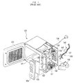
- FIG. 1 is a partially cutaway view showing a construction of a machine room of a conventional microwave oven.
- an oven body 120 is provided with a cooking cavity 121, and a machine room 122 in which a variety of electric and electronic devices are installed.
- a door 123 is attached to a front of the cooking cavity 121 to selectively open and close the cooking cavity 121, while a control panel 124 is attached to a front of the machine room 122 to control various operations of the conventional microwave oven.
- a circuit board 135 is positioned in back of the control panel 124 to control an entire operation of the microwave conventional oven in response to a manipulation of the control panel 124.
- High voltage devices including a magnetron 130, a high voltage transformer 131, a high voltage condenser 182, a high voltage diode 184, etc., are installed in the machine room 122.
- the magnetron 130 receives high voltage power from the high voltage devices 131, 182 and 184, and generates microwaves to irradiate the cooking cavity 121. As a result, food is cooked in the cooking cavity 121 by the microwaves irradiated by the magnetron 130.
- a blowing fan 132 is mounted on a back of the machine room 122 to suck outside air and cool the magnetron 130 with the sucked outside air.
- a noise filter 133 is installed at a position above the blowing fan 132 to eliminate high voltage noise.
- a power cord 134 is connected to the noise filter 133 to receive power from an outside power source (not shown).
- Power and control signals are supplied to the various electric and electronic devices positioned in the machine room 122 through two bundles of wires 140 and 150.
- the two bundles of wires 140 and 150 are a first bundle of wires 140 and a second bundle of wires 150 that supply the power and control signals to electric and electronic devices positioned on a rear and front portions of the machine room 122, respectively.
- the first and second bundles of wires 140 and 150 are electrically connected to each other through two terminals 142 and 152.
- Figure 2 is a circuit diagram of the conventional microwave oven, which shows electrical connections between the magnetron 130, the high voltage transformer 131, the high voltage condenser 182, the high voltage diode 184, and the noise filter 133.
- the magnetron 130 and the high voltage devices 131, 182 and 184 are mounted on a wall and a bottom of the machine room 122, respectively.
- the first and second bundles of wires 140 and 150 are intertwined to connect the magnetron 130 and the high voltage devices 131, 182 and 184 to corresponding locations.
- an aim of the present invention is to provide a microwave oven in which an assembly of a machine room is simplified. Ideally, utilization of the machine room is increased and/or a size of an oven body is reduced.
- a microwave oven having a magnetron that generates microwaves, a magnetron driving circuit that supplies high voltage power to the magnetron and a machine room that accommodates the magnetron and the magnetron driving circuit, which includes a magnetron driving circuit board in which the magnetron and the electronic devices of the magnetron driving circuit are mounted on a single board, wherein the magnetron driving circuit board is fixedly attached to the machine room by mounting units.
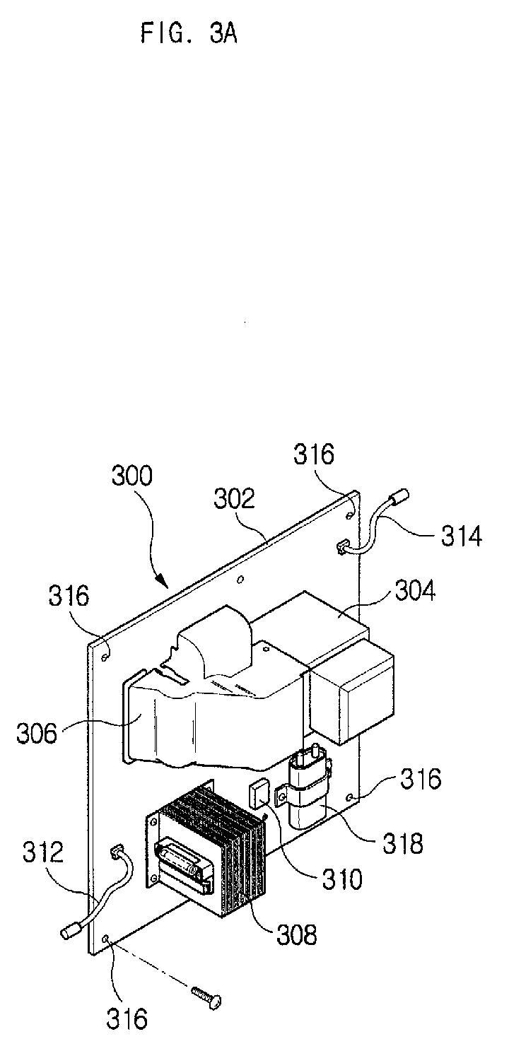
- FIGS. 3A and 3B are views of a magnetron driving circuit board 300 in accordance with the first embodiment of the present invention.
- a magnetron 304 and an air cover 306 are fixedly mounted on an upper portion of a circuit board 302.
- a high voltage condenser 318, a high voltage diode 310 and a high voltage transformer 308 are fixedly mounted on a lower portion of the circuit board 302 below the magnetron 304 and the air cover 306.
- the air cover 304 operates to supply air generated by a blowing fan (now shown) to an interior of a cooking cavity (not shown).
- the circuit board 302 is provided with a power cable 314 that supplies power and a control signal cable 312 that receives control signals from a control unit (not shown).
- the power cable 314 and the control signal cable 312 are, respectively, constructed in a form of a harness to be easily connected to a power terminal and control terminals, respectively.
- a plurality of mounting holes 316 is formed along edges of the circuit board 302 to receive mounting units.
- Figure 3B is a view showing a back of the magnetron driving circuit board 300.
- an antenna 322 of the magnetron 304 protrudes from the back of the magnetron driving circuit board 300, and microwaves irradiate through the antenna 322.
- An air inlet 320 is formed in the circuit board 302 to supply air supplied through the air cover 306, as shown in Figure 3A, to an interior of the cooking cavity.
- a waveguide (not shown) and an air inlet as shown in Figure 5 must be formed in a partition wall 508, situated between the machine room 506, and the cooking cavity of the body of the microwave oven employing the magnetron driving circuit board 300 to correspond to positions of the antenna 322 and the air inlet 320. Accordingly, a layout and specifications of the above-described parts may be designed at a stage of developing a product.
- Figure 4 is a diagram showing a wiring of the magnetron driving circuit board 300 of Figure 3A.
- wiring is set up between the magnetron 304, the high voltage condenser 318, the high voltage diode 310 and the high voltage transformer 308, so that an alternating current AC voltage is converted into a direct current DC voltage by a rectification of the high voltage diode 310 and a smoothing by the high voltage condenser, the converted direct current DC voltage is boosted to a certain voltage and the boosted voltage is supplied to the magnetron 304.
- the wiring may be implemented by general coated copper wires or in a patterning manner that is generally used in printed circuit boards.
- Figure 5 is a partially exploded perspective view showing an attachment of the magnetron driving circuit board 300 to the machine room 506.
- the magnetron driving circuit board 300 when the magnetron driving circuit board 300 is fixedly mounted on the partition wall 508 of the machine room 506, the magnetron 304 and the air cover 306 are arranged to face an antenna receiving hole 502 and an air inlet 504, respectively.
- the magnetron driving circuit board 300 By mounting the magnetron driving circuit board 300 on the partition wall 508 of the machine room 506 using mounting members 510, the mounting of the magnetron 304 and the high voltage devices 308, 310 and 318 used to drive the magnetron 304 can be simply achieved.
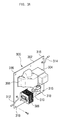
- FIGS. 6A and 6B are views of a magnetron driving circuit board in accordance with a second embodiment of the present invention, which shows a case where an air cover does not exist and a magnetron 604 and high voltage devices, such as the high voltage transformer 608, the high voltage diode 610 and the high voltage condenser 618, are mounted on a board 602.
- a magnetron 604 and high voltage devices such as the high voltage transformer 608, the high voltage diode 610 and the high voltage condenser 618
- the magnetron 604 is attached to the board 602 with a part of the magnetron 604 protruding from a front surface of the board 602.
- a plurality of mounting holes 650 is formed in the board 602.
- the magnetron 604 is secured to the board 602 by tightening mounting members into the mounting holes 650.
- a plurality of mounting holes 616 is formed on a back of the magnetron 604 so that the magnetron 604 is fixedly mounted on the partition wall separating the machine room and the cooking cavity of the oven body of the microwave oven by tightening mounting members into the plurality of mounting holes 616.
- the high voltage diode 610, a power cable 614, a control signal cable 612 and the high voltage condenser 618 are mounted on the front surface of the board 602, while the high voltage transformer 608 is mounted on a back surface of the board 602.
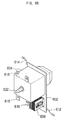
- Figure 6B is a view showing the back of the magnetron driving circuit board 600 of Figure 6A.
- the antenna 622 of the magnetron 604 protrudes from the back surface of the board 602, so microwaves irradiate from the antenna 622.
- the magnetron driving circuit board 600 is not provided with an air cover, a position of an installation of the magnetron driving circuit board 600 has to be determined in consideration of a position of a waveguide that is disposed between the machine room and the cooking cavity of the oven body of the microwave oven. Accordingly, a layout and specifications of the above-described parts may be designed at the stage of developing a product.
- a microwave oven in which a magnetron and other high voltage devices are mounted on a single circuit board to be packaged, so that an assembly of a machine room can be simplified, and utilization of the machine room can be increased or a size of an oven body can be reduced.
Landscapes
- Physics & Mathematics (AREA)
- Electromagnetism (AREA)
- Engineering & Computer Science (AREA)
- Chemical & Material Sciences (AREA)
- Combustion & Propulsion (AREA)
- Mechanical Engineering (AREA)
- General Engineering & Computer Science (AREA)
- Electric Ovens (AREA)
- Control Of High-Frequency Heating Circuits (AREA)
- Constitution Of High-Frequency Heating (AREA)
Abstract
Description
Claims (18)
- A magnetron driving circuit generating high voltage power used to drive a magnetron (304), comprising:a single magnetron driving circuit board (302) in which the magnetron and electronic devices (308,310,318) of the magnetron driving circuit are mounted thereon.
- The magnetron driving circuit as set forth in claim 1, wherein the electronic devices (308,310,318) include a high voltage transformer (308), a high voltage diode (310) and a high voltage condenser (318).
- The magnetron driving circuit as set forth in claim 1 or 2, wherein the electronic devices (308,310,318) are electrically connected to one another by coated copper wires.
- The magnetron driving circuit as set forth in claim 1, 2 or 3, wherein the electronic devices (308,310,318) are electrically connected to one another in a patterning manner that is used in printed circuit boards.
- The magnetron driving circuit as set forth in any preceding claim, wherein the electronic devices (308,310,318) are mounted on opposite sides of the single circuit board.
- The magnetron driving circuit as set forth in any preceding claim, wherein the high voltage condenser (318) and the high voltage diode (310) are mounted on a first surface of the single magnetron driving circuit board (302) and the high voltage transformer (308) is mounted on a second surface of the single magnetron driving circuit board (302).
- The magnetron driving circuit as set forth in any preceding claim, further comprising:a power cable (314) used to receive power from an outside source; anda control signal cable (312) used to receive control signals from a control unit.
- The magnetron driving circuit as set forth in claim 7, wherein the power cable (314) and control signal cable (312), respectively, are constructed in a form of a harness.
- The magnetron driving circuit as set forth in any preceding claim, wherein at least one mounting hole is formed in the single magnetron driving circuit board (302) and the single magnetron driving circuit board (302) is fixedly attached to a machine room by tightening a mounting member (510) into the or each mounting hole.
- The magnetron as set forth in any preceding claim, further comprising:an air cover (306) mounted on the single magnetron driving circuit board (302) to supply air to a cooking cavity of a microwave oven.
- A microwave oven having a magnetron (304) that generates microwaves, a magnetron driving circuit (308,310,318) that supplies high voltage power to the magnetron (304) and a machine room (506) that accommodates the magnetron (304) and the magnetron driving circuit (308,310,318), comprising:a single magnetron driving circuit board (302) in which the magnetron (304) and electronic devices (308,310,318) of the magnetron driving circuit are mounted thereon, as set forth in any preceding claim; andmounting members (510) such that the magnetron driving circuit board (302) is fixedly attached to the machine room (506) by the mounting members (510).
- The microwave oven as set forth in claim 11, wherein the mounting members (510) comprise:mounting holes (650) formed along an edge of the single circuit board (602); andmounting units (510) to be received in the mounting holes to couple the single circuit board (602) to the machine room (506).
- The microwave oven of claim 11 or 12, wherein:the magnetron (604) is attached to the single circuit board (602) with part of the magnetron (604) protruding from a surface of the board (602); andat least one mounting hole (616) is formed on the protruding part of the magnetron (604), such that the magnetron (604) is fixedly mountable to a machine room (506) to support the single circuit board (602).
- The microwave oven as set forth in claim 11, 12 or 13, wherein:the magnetron (604) is mounted on one side of the single circuit board (602) and comprises:an antenna (622) to radiate the microwaves generated by the magnetron (604); andthe single circuit board (602) comprises:an antenna receiving hole (502) in the single circuit board such that the antenna of the magnetron protrudes therethrough from an opposite side of single circuit board.
- The microwave oven as set forth in any of claims 11 to 14, further comprising:a cooking cavity to cook food disposed in the microwave oven; andan air cover (306) mounted on the single circuit board to supply air to the cooking cavity.
- The microwave oven as set forth in claim 15, further comprising:a waveguide formed between the machine room and the cooking cavity; andan air inlet (504) formed between the machine room and the cooking cavity wherein the single circuit board is positioned according to positions of the waveguide and the air inlet.
- The microwave oven as set forth in claim 15 or 16, further comprising:a waveguide formed between the machine room and the cooking cavity; andan air inlet (504) formed between the machine room and the cooking cavity wherein the single circuit board is positioned such that the antenna of the magnetron and the air cover of the single circuit board correspond to positions of the waveguide and the air inlet, respectively.
- A microwave oven having a magnetron (304) that generates microwaves, a magnetron driving circuit (300) that supplies power to the magnetron and a machine room (506) to accommodate the magnetron and the magnetron driving circuit, comprising:a constructional unit comprising:electronic components (308,310,318) of the magnetron driving circuit (300);the magnetron (304); anda magnetron driving circuit board (302), the magnetron (302) and the electronic components (308,310,318) of the magnetron driving circuit (300) being mounted thereon; andmounting member (510) to couple the constructional unit to the machine room (506).
Applications Claiming Priority (2)
| Application Number | Priority Date | Filing Date | Title |
|---|---|---|---|
| KR10-2002-0055990A KR100512031B1 (en) | 2002-09-14 | 2002-09-14 | Magnetron driving circuit board of microwave oven |
| KR2002055990 | 2002-09-14 |
Publications (2)
| Publication Number | Publication Date |
|---|---|
| EP1398998A2 true EP1398998A2 (en) | 2004-03-17 |
| EP1398998A3 EP1398998A3 (en) | 2006-11-08 |
Family
ID=31885020
Family Applications (1)
| Application Number | Title | Priority Date | Filing Date |
|---|---|---|---|
| EP03250972A Withdrawn EP1398998A3 (en) | 2002-09-14 | 2003-02-19 | Magnetron driving circuit board for microwave oven |
Country Status (5)
| Country | Link |
|---|---|
| US (1) | US6906298B2 (en) |
| EP (1) | EP1398998A3 (en) |
| JP (1) | JP3776093B2 (en) |
| KR (1) | KR100512031B1 (en) |
| CN (1) | CN1286346C (en) |
Cited By (1)
| Publication number | Priority date | Publication date | Assignee | Title |
|---|---|---|---|---|
| EP3258741A1 (en) * | 2016-06-13 | 2017-12-20 | E.G.O. ELEKTRO-GERÄTEBAU GmbH | Microwave generator for a microwave apparatus and microwave apparatus |
Families Citing this family (8)
| Publication number | Priority date | Publication date | Assignee | Title |
|---|---|---|---|---|
| KR100556609B1 (en) * | 2004-02-20 | 2006-03-06 | 삼성전자주식회사 | microwave |
| JP2006129687A (en) * | 2004-10-01 | 2006-05-18 | Nec Tokin Corp | Ac adapter |
| EP1815645A1 (en) * | 2004-11-15 | 2007-08-08 | Koninklijke Philips Electronics N.V. | Detection of the operation of a microwave oven by scanning medium noise pattern |
| WO2011028724A1 (en) * | 2009-09-01 | 2011-03-10 | Manitowoc Foodservice Companies, Llc. | Method and apparatus for venting a cooking device |
| CN103591619B (en) * | 2012-08-16 | 2016-03-23 | 广东美的厨房电器制造有限公司 | Micro-wave oven and control method thereof |
| GB2512819B (en) * | 2013-03-18 | 2021-07-14 | Wayv Tech Limited | Microwave heating apparatus |
| US11612022B2 (en) * | 2018-03-09 | 2023-03-21 | Rockwell Collins, Inc. | Magnetron filter board for microwave oven |
| WO2023076278A1 (en) * | 2021-10-27 | 2023-05-04 | Mks Instruments, Inc. | Power supply apparatus |
Family Cites Families (11)
| Publication number | Priority date | Publication date | Assignee | Title |
|---|---|---|---|---|
| JPH04121991A (en) * | 1990-09-11 | 1992-04-22 | Matsushita Electric Ind Co Ltd | High frequency heating device |
| JPH0620770A (en) * | 1991-10-29 | 1994-01-28 | Matsushita Electric Ind Co Ltd | High frequency heating device |
| US5797211A (en) * | 1995-06-28 | 1998-08-25 | Bae; Tae Hong | Position-sensing light and alarm for a fishing rod |
| KR0136064Y1 (en) * | 1995-10-09 | 1999-03-20 | 김광호 | Microwave power cord thermal damage prevention device |
| KR970063302U (en) * | 1996-05-20 | 1997-12-11 | Fixing structure of high pressure parts of microwave oven | |
| JP3176035B2 (en) * | 1996-07-16 | 2001-06-11 | 株式会社東芝 | Cooking device |
| KR100301902B1 (en) * | 1997-11-15 | 2001-11-22 | 구자홍 | Magnetron mounting structure of microwave oven |
| US6362463B1 (en) * | 1998-08-06 | 2002-03-26 | Matsushita Electric Industrial Co., Ltd. | High frequency heating apparatus |
| KR200296186Y1 (en) * | 1999-05-27 | 2002-11-23 | 삼성전자 주식회사 | Structure for fixing HVC and HVD of a microwave oven |
| KR20010094636A (en) * | 2000-03-31 | 2001-11-01 | 윤종용 | Structure For Arrangement Parts Of a DC Microwave Oven |
| JP4779245B2 (en) * | 2000-06-28 | 2011-09-28 | パナソニック株式会社 | Inverter device |
-
2002
- 2002-09-14 KR KR10-2002-0055990A patent/KR100512031B1/en not_active Expired - Fee Related
-
2003
- 2003-02-11 CN CNB031038069A patent/CN1286346C/en not_active Expired - Fee Related
- 2003-02-19 EP EP03250972A patent/EP1398998A3/en not_active Withdrawn
- 2003-03-24 US US10/393,986 patent/US6906298B2/en not_active Expired - Fee Related
- 2003-04-10 JP JP2003106949A patent/JP3776093B2/en not_active Expired - Lifetime
Cited By (2)
| Publication number | Priority date | Publication date | Assignee | Title |
|---|---|---|---|---|
| EP3258741A1 (en) * | 2016-06-13 | 2017-12-20 | E.G.O. ELEKTRO-GERÄTEBAU GmbH | Microwave generator for a microwave apparatus and microwave apparatus |
| US10667338B2 (en) | 2016-06-13 | 2020-05-26 | E.G.O. Elektro-Geraetebau Gmbh | Microwave generator for a microwave device and microwave device |
Also Published As
| Publication number | Publication date |
|---|---|
| JP2004111351A (en) | 2004-04-08 |
| US6906298B2 (en) | 2005-06-14 |
| US20040050842A1 (en) | 2004-03-18 |
| EP1398998A3 (en) | 2006-11-08 |
| KR100512031B1 (en) | 2005-09-02 |
| JP3776093B2 (en) | 2006-05-17 |
| KR20040024393A (en) | 2004-03-20 |
| CN1286346C (en) | 2006-11-22 |
| CN1482837A (en) | 2004-03-17 |
Similar Documents
| Publication | Publication Date | Title |
|---|---|---|
| JP7550370B2 (en) | Light source unit and lighting fixture | |
| EP1398998A2 (en) | Magnetron driving circuit board for microwave oven | |
| JP2010140657A (en) | Induction heating cooking appliance | |
| JP2026042915A (en) | Light source unit and lighting fixture | |
| US6720542B2 (en) | Microwave oven and method of manufacturing the same | |
| JP4922136B2 (en) | Induction heating cooker | |
| JP3123446B2 (en) | High frequency heating equipment | |
| JP7008211B2 (en) | Dimmer | |
| JP3468019B2 (en) | High voltage circuit for power supply of high frequency heating device | |
| CN100455903C (en) | Microwave oven wire connection structure | |
| JP2002199740A (en) | Inverter unit and product using it | |
| KR200337663Y1 (en) | Earth structure of noise filter for a microwave oven | |
| KR101043100B1 (en) | Flat Panel Display | |
| KR200335087Y1 (en) | Earth structure of noise filter for a microwave oven | |
| KR20010035674A (en) | Microwave oven having a radio | |
| KR100189115B1 (en) | Microwave oven | |
| KR200229343Y1 (en) | Mounting Structure of High Voltage Transformer for Ventillation Hooded Microwave Oven | |
| KR20030080777A (en) | Fastening structure of power cord in microwave oven | |
| KR200160256Y1 (en) | Microwave | |
| JP2001015258A (en) | microwave | |
| EP0868113A2 (en) | Electrical appliance | |
| KR20090009782U (en) | Microwave oven having cooling structure with single fan | |
| KR19990023551U (en) | Microwave Wiring Fixture | |
| KR19990003819A (en) | Microwave Harness Removal Device | |
| JP2001110559A (en) | High frequency heating equipment |
Legal Events
| Date | Code | Title | Description |
|---|---|---|---|
| PUAI | Public reference made under article 153(3) epc to a published international application that has entered the european phase |
Free format text: ORIGINAL CODE: 0009012 |
|
| 17P | Request for examination filed |
Effective date: 20030304 |
|
| AK | Designated contracting states |
Kind code of ref document: A2 Designated state(s): AT BE BG CH CY CZ DE DK EE ES FI FR GB GR HU IE IT LI LU MC NL PT SE SI SK TR |
|
| AX | Request for extension of the european patent |
Extension state: AL LT LV MK RO |
|
| PUAL | Search report despatched |
Free format text: ORIGINAL CODE: 0009013 |
|
| AK | Designated contracting states |
Kind code of ref document: A3 Designated state(s): AT BE BG CH CY CZ DE DK EE ES FI FR GB GR HU IE IT LI LU MC NL PT SE SI SK TR |
|
| AX | Request for extension of the european patent |
Extension state: AL LT LV MK RO |
|
| AKX | Designation fees paid |
Designated state(s): DE FR GB |
|
| STAA | Information on the status of an ep patent application or granted ep patent |
Free format text: STATUS: THE APPLICATION HAS BEEN WITHDRAWN |
|
| 18W | Application withdrawn |
Effective date: 20071128 |