EP1398860A2 - Electrical extension lead - Google Patents
Electrical extension lead Download PDFInfo
- Publication number
- EP1398860A2 EP1398860A2 EP03020170A EP03020170A EP1398860A2 EP 1398860 A2 EP1398860 A2 EP 1398860A2 EP 03020170 A EP03020170 A EP 03020170A EP 03020170 A EP03020170 A EP 03020170A EP 1398860 A2 EP1398860 A2 EP 1398860A2
- Authority
- EP
- European Patent Office
- Prior art keywords
- extension lead
- battery pack
- housing
- cable
- storage structure
- Prior art date
- Legal status (The legal status is an assumption and is not a legal conclusion. Google has not performed a legal analysis and makes no representation as to the accuracy of the status listed.)
- Granted
Links
Images

Classifications
-
- H—ELECTRICITY
- H02—GENERATION; CONVERSION OR DISTRIBUTION OF ELECTRIC POWER
- H02J—ELECTRIC POWER NETWORKS; CIRCUIT ARRANGEMENTS OR SYSTEMS FOR SUPPLYING OR DISTRIBUTING ELECTRIC POWER; SYSTEMS FOR STORING ELECTRIC ENERGY
- H02J7/00—Circuit arrangements for charging or discharging batteries or for supplying loads from batteries
- H02J7/70—Circuit arrangements for charging or discharging batteries or for supplying loads from batteries characterised by the mechanical construction
-
- H—ELECTRICITY
- H01—ELECTRIC ELEMENTS
- H01R—ELECTRICALLY-CONDUCTIVE CONNECTIONS; STRUCTURAL ASSOCIATIONS OF A PLURALITY OF MUTUALLY-INSULATED ELECTRICAL CONNECTING ELEMENTS; COUPLING DEVICES; CURRENT COLLECTORS
- H01R13/00—Details of coupling devices of the kinds covered by groups H01R12/70 or H01R24/00 - H01R33/00
- H01R13/72—Means for accommodating flexible lead within the holder
-
- H—ELECTRICITY
- H02—GENERATION; CONVERSION OR DISTRIBUTION OF ELECTRIC POWER
- H02G—INSTALLATION OF ELECTRIC CABLES OR LINES, OR OF COMBINED OPTICAL AND ELECTRIC CABLES OR LINES
- H02G11/00—Arrangements of electric cables or lines between relatively-movable parts
- H02G11/02—Arrangements of electric cables or lines between relatively-movable parts using take-up reel or drum
-
- H—ELECTRICITY
- H01—ELECTRIC ELEMENTS
- H01R—ELECTRICALLY-CONDUCTIVE CONNECTIONS; STRUCTURAL ASSOCIATIONS OF A PLURALITY OF MUTUALLY-INSULATED ELECTRICAL CONNECTING ELEMENTS; COUPLING DEVICES; CURRENT COLLECTORS
- H01R25/00—Coupling parts adapted for simultaneous co-operation with two or more identical counterparts, e.g. for distributing energy to two or more circuits
- H01R25/003—Coupling parts adapted for simultaneous co-operation with two or more identical counterparts, e.g. for distributing energy to two or more circuits the coupling part being secured only to wires or cables
Definitions
- This invention relates generally to electrical extension leads, in particular of the type which are wound on a drum or reel.
- Electrical extension leads have a cable with an electrical plug at one end of the cable for connection, for example to a plug socket of an electrical supply source, such as a mains supply or a fuel, eg. petrol, powered generator supply.
- an electrical supply source such as a mains supply or a fuel, eg. petrol, powered generator supply.
- the extension cable is wound on a drum, the other end of the cable is electrically connected to at least one plug socket assembly located on the drum.
- an electrical appliance for example a power tool
- the one end of the cable is connected via the plug to said plug socket and a suitable length of cable is unwound form the drum.
- a plug at the end of the electrical cable of the power tool is plugged into the plug socket arrangement of the drum and the power tool can be used in the remote location.
- Not all power tools are powered by connecting them to an electrical supply source, for example the mains, but instead are powered by battery packs.
- an electrical supply source for example the mains
- battery packs When conducting a job at a location remote from, for example a mains supply, there are situations when a user will use mains powered and battery powered tools to complete the job. For example, a user may need to use a mains powered saw and a battery powered drill. Where battery powered tools are being used in such a location the batteries have to be recharged, generally by a battery charger connected to the remote mains source.
- the present invention aims to provide a more convenient arrangement for charging batteries when working at a location remote from a electrical supply source.
- an electrical extension lead comprising an electrical cable having a first end and a second end, having the first end connected to a plug socket arrangement for supplying electricity to electrical devices, and with the second end connected to an electrical plug for connection to an electrical supply source, for example a mains or generator supply source, characterised in that a battery pack charging assembly is also connected to the first end of the cable, which charging assembly is suitable for charging battery packs for powering electrical devices.
- an electrical supply source for example a mains or generator supply source
- a person working at a location remote from an electrical supply source for example the mains, and using an electrical extension lead, is able to charge batteries in situ, ie. at the location in which he or she is working, during the entire time during which the plug of the extension lead is electrically connected to the mains supply.
- a mains powered device for example a power tool
- a battery pack can be charged.
- the battery pack being charged could be the only battery pack for the battery powered device, or it could be a spare which is being charged while a second battery pack is being used to power the device.
- plug socket arrangement and the battery pack charging assembly are co-located so as to make the electrical extension lead easily portable and compact. It is especially preferred that the plug socket arrangement and the battery pack charging assembly are mounted within a common housing arrangement.
- the cable may be stored by wrapping it around a storage structure, which storage structure is part of the extension lead. This reduces the time to deploy the cable, as the cable is less likely to become tangled if stored by being wrapped around a storage structure.
- the storage structure may comprise a housing configured as a reel, around which the cable can be wrapped. Where such a storage structure is used, the plug socket assembly and the battery pack charging assembly are preferably mounted on the storage structure. This reduces the number of separate parts required for storage and use of the extension lead according to the present invention.
- the cable is stored by wrapping it around the exterior surface of a hollow storage structure and the battery pack charging assembly is located within said hollow storage structure.
- the plug socket assembly is fitted within a cover portion at a first end of the hollow storage structure and the battery pack charging assembly is fitted within a cover portion at a second opposite end of the hollow storage structure.
- the second cover portion may be formed as the walls of a recess, which recess extends within the hollow storage structure and within which recess the battery pack charging assembly is mounted.
- the hollow storage structure is substantially cylindrical.
- the storage structure around which the cable is wrapped may be rotatably mounted within an outer housing, which outer housing is formed with a hole through which the cable (8) is extendable.
- the storage structure in order to deploy that cable, the storage structure is rotated with respect to the outer housing in a first direction in order to unwrap the cable from the storage structure. Then to store the cable, after use, the storage structure is rotated with respect to the outer housing in a second opposite direction in order to re-wrap the cable around the storage structure.
- the battery pack charging assembly generally comprises a receptacle assembly for receiving a battery pack, which receptacle assembly comprises a receptacle housing and a flexible, preferably elastomeric, gasket disposed between the receptacle housing and a portion of the extension lead housing.
- the use of the elastomeric gasket damps any vibration from the extension lead housing, if for example, the extension lead housing is dropped, in order to protect the receptacle assembly and any battery pack mounted within it from damage.
- the receptacle assembly further comprises at least one retainer disposed on the extension lead housing to prevent disengagement of the gasket.
- a door located adjacent the receptacle assembly can be hingably connected to the extension lead housing in order to cover the receptacle assembly.
- the door preferably has a spring disposed on it to bias a battery disposed in the receptacle assembly towards a connecting position.
- the battery charger circuitry is mounted on the receptacle housing.
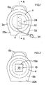
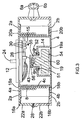
- the cable drum arrangement shown in Figures 1 to 3 has a two part clamshell housing (2a) and (2b) within which a storage structure, such as a reel housing (4) is mounted.
- Each clamshell half has an annular wall (20a, 20b) (the forward or rearward side of the clamshell housing) with a peripheral annular side wall (22a, 22b). Each side wall extends substantially at right angles to the associated annular wall.
- Each annular wall (20a, 20b) of the clamshell halves has a central recess within which the reel housing (4) is sandwiched by fixing the edges of the side walls (22a, 22b) remote from the annular walls (20a, 20b) together, for example, using screws (28).
- Each clamshell half is formed with a respective half of a handle (6a, 6b) by which the cable drum can be carried and hung on a hook for storage.
- the reel housing (4) has a central cylindrical body (4c), about which a cable (8) is wound or wrapped and at the ends of the cylindrical body (4c) are formed annular flanges (4a) and (4b).
- a first end of the cylindrical body (4a) has a cover portion formed with a through hole for receiving a plug socket assembly (12).
- the second opposite end of the cylindrical body (4a) has a cover portion formed with a recess (14) for receiving a battery charging assembly (15) and a battery (60).
- the reel housing (4) is received between the clamshell housing parts (2a, 2b) so as to be able to rotate with respect to the clamshell housing.
- Each clamshell half is formed on the internal surface of its annular wall (20a, 20b) with an annular rib (16a, 16b) which fits around the associated annular flange (4a, 4b).
- the reel housing (4) is formed with an external annular shoulder (18a, 18b) at each end of the cylindrical body (4a) against which a radially inward portions of the annular walls (20a, 20b) abut.
- the reel housing (4) is formed with a handle (24), located eccentrically with respect to the rotational axis of the reel housing (4), on the cover portion of the reel housing in which the plug socket assembly is mounted. This handle can be gripped by a user to facilitate relative rotation between the reel housing (4) and the clamshell housing (2a, 2b).
- a cable (8) is connected at a first end (26) to the plug socket assembly (12) and to the battery charging assembly (15).
- the cable is wound around the outside of the cylindrical body (4a) of the reel housing (4) between the two flanges (4a, 4b).
- the first end of the cable is secured in place by pegs (30) depending from the inside facing surface of the plug socket assembly (12) between which pegs (30) the first end (26) of the cable (8) is secured.
- the second opposite end of the cable (8) extends through a hole (32) in the clamshell housing (2a, 2b) and has an electrical plug (34) electrically connected to it.
- a desired length of the cable (8) can be drawn out of the recess (32) in the clamshell housing (2a, 2b) by a relative rotation of the reel housing (4) to the clamshell housing (2a, 2b).
- the electrical circuitry for the cable drum is shown in Figure 4.
- the cable (8) has neutral, live and earth wires, which are connected at the first end (26) of the cable to the neutral, live and earth connectors, respectively of three plug sockets of the plug socket arrangement (12) in a conventional manner.
- the recess (14) in the cover portion of the reel housing (4) remote from the plug socket assembly (12) has a door (19) pivotally attached thereto, providing access to recess (14) and allowing an operator to install a battery pack (60) within reel housing (4).
- the door (19) may be kept in a closed position by latch (18).
- latch (18) comprises an overcenter mechanism.
- Door (19) may have a gasket (19a) disposed thereon to limit the ingress of water into, if not wholly waterproof, recess (14).
- gasket (19a) is made of rubber or an elastomeric material.
- the recess (14) is designed to receive a battery pack (60) via a connector (56).
- the connector (56) has a configuration appropriate to contact the battery terminals.
- the battery pack terminals and connector (56) will be arranged in the manner disclosed in U.S. Patent No. 5,144,217, which is hereby incorporated in whole by reference.
- the charger circuitry (43) is electrically connected to the connector (56) and the connector (56) and the charger circuitry are mounted on a floating receptacle housing (55). They are mounted on the floating receptacle housing (55), to minimize the shock received by the battery pack (60) and the circuitry (43) if the cable drum is dropped.
- Charger circuitry (43) allows charging of battery packs having different voltages, as is well known in the art.
- the receptacle housing (55) may be flexibly connected to the walls of the recess (14) via a flexible gasket (51).
- gasket (51) is generally annular and made of a flexible, resilient material, such as rubber or elastomer.
- Retainers (52) may be installed on the walls of the recess (14) to prevent the disengagement of gasket (51) and the walls of the recess (14) when pushing the battery pack (60) in place.
- Retainers (52) may be attached to walls of the recess (14) via screws and may have a generally annular form.
- a spring (54) may also be provided on door (19) to bias battery pack (60) into connection with connector (56).
- spring (54) will be flexible enough to bias battery packs having different sizes.
- the charger circuitry (43) is connected to the mains power supply via the cable (8) and plug (34).
- an electrical supply source for example a mains power supply (40)
- power is provided to the charger (43) in order to charge battery pack (60). While the battery pack (60) is being charged the plug sockets of the plug socket assembly are still available for use to power up to three electrically powered device, such as power tools.
- a user can charge a battery pack by disposing the battery pack (60) in the charger (43), providing power to the battery pack (60), and then removing the battery pack (60) from the charger (43), while using a first powered power tool, such as a saw, plugged into the plug socket arrangement (12) of the extension lead.
- the charged battery pack (60) can then be inserted into a battery powered power tool, such as drill for a user to continue with the job in hand.
- the user can use the extension lead for powering electrical devices, while charging the battery pack (60).
- FIG. 5 shows a second embodiment of the present invention, with like parts identified by like numerals.
- the electrical circuitry of the Figure 5 embodiment is the same as that shown in Figure 4, but with one plug socket removed.
- the electrical extension lead has a housing (2) formed from upper and lower clamshell halves, the upper one of which can be seen in Figure 5.
- the housing (2) houses a plug socket arrangement (12) comprising two plug sockets.
- the housing (2) also houses a battery pack charging assembly, located in a recess behind the door (19), which door (19) is secured shut by a latch arrangement (18).
- the battery pack charging assembly could for example be identical to that shown in Figure 3.
- a cable (8) extends from the housing (2) and the end of the cable (8) remote from the housing has a plug (34) electrically connected to it.
- the plug (34) When the plug (34) is electrically connected to an electrical supply source, such as a generator or mains supply, up to two electrically powered devices can be plugged into the sockets of the socket arrangement (12) in order to power the electrically powered devices.
- a battery pack (60) can be inserted into the battery pack charging assembly of the electrical extension lead of Figure 5, in order to simultaneously charge the battery pack for later use on a battery powered device.
- the cable (8) When the electrical extension lead of Figure 5 is stored, the cable (8) can be wound around a forearm of a user and hung on a hook, with the housing (2) also hung on the hook via hanging loop (17).
- the housing (2) could be provided with flanges (15) (shown in dotted lines) and the cable (8) could be wrapped or wound around the housing (2) between the flanges (15). The housing (2) with the cable (8) wrapped around it could then be stored by hanging the housing (2) on a hook via hanging loop (17).
Landscapes
- Engineering & Computer Science (AREA)
- Power Engineering (AREA)
- Charge And Discharge Circuits For Batteries Or The Like (AREA)
- Battery Mounting, Suspending (AREA)
- Piezo-Electric Or Mechanical Vibrators, Or Delay Or Filter Circuits (AREA)
- Vessels And Coating Films For Discharge Lamps (AREA)
- Insulated Conductors (AREA)
- Communication Cables (AREA)
Abstract
Description
Claims (17)
- An electrical extension lead, comprising an electrical cable (8) having a first end (26) and a second end, having the first end connected to a plug socket arrangement (12) for supplying electricity to electrical devices, and with the second end connected to an electrical plug (34) for connection to an electrical supply source, characterised in that a battery pack charging assembly (15) is also connected to the first end of the cable, which charging assembly is suitable for charging battery packs for powering electrical devices.
- An extension lead according to claim 1 wherein the plug socket arrangement (12) and the battery pack charging assembly (15) are co-located.
- An extension lead according to any one of the preceding claims wherein the plug socket arrangement (12) and the battery pack charging assembly (15) are mounted within a common housing arrangement (2a, 2b, 4).
- An extension lead according to any one of the preceding claims wherein the extension lead comprises a storage structure (4) and the cable (8) is stored by wrapping it around the storage structure (4).
- An extension lead according to claim 4 wherein the storage structure is a reel housing (4).
- An extension lead according to claim 4 or claim 5 wherein the plug socket arrangement (12) and the battery pack charging assembly (15) are mounted on the storage structure.
- An extension lead according to any one of the preceding claims wherein the cable (8) is stored by wrapping it around the exterior surface of a hollow storage structure (4) and the battery pack charging assembly (15) is located within said hollow storage structure.
- An extension lead according to claim 7 wherein the plug socket arrangement (12) is fitted within a cover portion at a first end of the hollow structure (4) and the battery pack charging assembly (15) is fitted within a cover portion (14) at a second opposite end of the hollow structure.
- An extension lead according to claim 8 wherein the second cover portion (14) is formed as the walls of a recess, which recess extends within the hollow storage structure.
- An extension lead according to any one of claims 7 to 9 wherein the hollow storage structure is substantially cylindrical.
- An extension lead according to claim 4 or any one of claims 5 to 10 when dependent on claim 4, wherein storage structure (4) is rotatably mounted within an outer housing (2a, 2b), which outer housing is formed with a hole (32) through which the cable (8) is extendable.
- An extension lead according to claim 3 or any of claims 4 to 11 when dependent on claim 3 wherein the battery pack charging assembly (15) comprises a receptacle assembly for receiving a battery pack (60), which receptacle assembly comprises a receptacle housing (55) and a flexible, preferably elastomeric, gasket (51) disposed between the receptacle housing and a portion (14) of the extension lead housing (4, 2a, 2b).
- An extension lead as claimed in Claim 12, wherein the receptacle assembly further comprises at least one retainer (52) disposed on the extension lead housing (2a, 2b, 4) to prevent disengagement of the gasket (51).
- An extension lead as claims in claim 12 or 13, further comprising a door (19) in the extension lead housing (4) located adjacent the receptacle assembly, the door preferably having a spring (54) disposed thereon to bias a battery (60) disposed in the receptacle assembly towards a connecting position.
- An extension lead as claimed in any one of claims 12 to 14 wherein the battery charger circuitry (43) is mounted on the receptacle housing (55).
- An extension lead as claimed in any one of the preceding claims wherein the electrical supply source is a mains supply source or a fuel powered generator supply source.
- An extension lead substantially as hereinbefore described with reference to any one of the accompanying Figures.
Priority Applications (1)
| Application Number | Priority Date | Filing Date | Title |
|---|---|---|---|
| EP06120567A EP1727255A3 (en) | 2002-09-11 | 2003-09-05 | Electrical extension lead |
Applications Claiming Priority (2)
| Application Number | Priority Date | Filing Date | Title |
|---|---|---|---|
| GB0220994A GB2393042B (en) | 2002-09-11 | 2002-09-11 | Electrical extension lead |
| GB0220994 | 2002-09-11 |
Related Child Applications (2)
| Application Number | Title | Priority Date | Filing Date |
|---|---|---|---|
| EP06120567A Division EP1727255A3 (en) | 2002-09-11 | 2003-09-05 | Electrical extension lead |
| EP06120567A Division-Into EP1727255A3 (en) | 2002-09-11 | 2003-09-05 | Electrical extension lead |
Publications (4)
| Publication Number | Publication Date |
|---|---|
| EP1398860A2 true EP1398860A2 (en) | 2004-03-17 |
| EP1398860A3 EP1398860A3 (en) | 2004-06-16 |
| EP1398860B1 EP1398860B1 (en) | 2007-01-03 |
| EP1398860B3 EP1398860B3 (en) | 2009-03-11 |
Family
ID=9943804
Family Applications (2)
| Application Number | Title | Priority Date | Filing Date |
|---|---|---|---|
| EP03020170A Expired - Lifetime EP1398860B3 (en) | 2002-09-11 | 2003-09-05 | Electrical extension lead |
| EP06120567A Withdrawn EP1727255A3 (en) | 2002-09-11 | 2003-09-05 | Electrical extension lead |
Family Applications After (1)
| Application Number | Title | Priority Date | Filing Date |
|---|---|---|---|
| EP06120567A Withdrawn EP1727255A3 (en) | 2002-09-11 | 2003-09-05 | Electrical extension lead |
Country Status (6)
| Country | Link |
|---|---|
| US (1) | US7429189B2 (en) |
| EP (2) | EP1398860B3 (en) |
| AT (1) | ATE350795T1 (en) |
| AU (1) | AU2003244601B2 (en) |
| DE (2) | DE60310828D1 (en) |
| GB (1) | GB2393042B (en) |
Cited By (2)
| Publication number | Priority date | Publication date | Assignee | Title |
|---|---|---|---|---|
| EP2345555A4 (en) * | 2008-10-09 | 2012-11-21 | Toyota Motor Co Ltd | CONNECTING DEVICE |
| CN111370950A (en) * | 2020-04-15 | 2020-07-03 | 威海市复点电子科技有限公司 | A data cable storage device that can automatically take up the cable |
Families Citing this family (17)
| Publication number | Priority date | Publication date | Assignee | Title |
|---|---|---|---|---|
| US6427070B1 (en) * | 1999-03-04 | 2002-07-30 | Black & Decker Inc. | Heavy-duty audio equipment |
| CN101330179B (en) * | 2007-06-21 | 2011-03-16 | 俞国麟 | Power source socket |
| US8027737B2 (en) * | 2007-08-01 | 2011-09-27 | Intelect Medical, Inc. | Lead extension with input capabilities |
| US20090183708A1 (en) * | 2008-01-17 | 2009-07-23 | Jung-Yuang Liu | Starting module assembly of remote control car |
| AU2009277093B2 (en) * | 2008-07-30 | 2015-01-29 | Snap-On Incorporated | Power strip with input plug |
| AU2012312172B8 (en) * | 2011-09-23 | 2017-05-18 | C5 Systems, Llc | Stackable cable reel with field data distribution system |
| JP5877108B2 (en) * | 2011-11-09 | 2016-03-02 | 中央発條株式会社 | Cable housing device |
| CN105027366B (en) * | 2013-01-07 | 2017-12-19 | Q有限责任公司 | reconfigurable socket device and method |
| US10232479B2 (en) | 2013-05-06 | 2019-03-19 | Milwaukee Electric Tool Corporation | Power tool including a battery pack isolation system |
| TWM505489U (en) * | 2015-02-17 | 2015-07-21 | rui-feng Xu | Wire collection device |
| USD812010S1 (en) | 2016-04-11 | 2018-03-06 | Tti (Macao Commercial Offshore) Limited | Modular extension cord reel |
| US10950990B2 (en) * | 2018-04-02 | 2021-03-16 | One-Eyed Pilot Innovations, Inc. | Reel based outlet relocation/extension system |
| USD951869S1 (en) | 2018-07-13 | 2022-05-17 | One-Eyed Pilot Innovations, Inc. | Wall socket extender |
| DE102018122065A1 (en) * | 2018-09-11 | 2020-03-12 | HEDI GmbH Elektro- und Gerätebau | Cable drum with inclined drum axis |
| US12512635B2 (en) * | 2022-01-25 | 2025-12-30 | The Stanley Works Israel Ltd. | Stackable power outlet box |
| EP4620624A3 (en) | 2022-06-16 | 2026-01-21 | Milwaukee Electric Tool Corporation | Compact impact tool |
| CN219007631U (en) * | 2022-11-30 | 2023-05-12 | 深圳市冠科科技有限公司 | Charging pile |
Family Cites Families (48)
| Publication number | Priority date | Publication date | Assignee | Title |
|---|---|---|---|---|
| GB236916A (en) | 1924-07-14 | 1925-11-12 | Vogtlandische Maschinenfabrik | Improvements in two stroke cycle crude oil engines for motor vehicles |
| US4079304A (en) * | 1976-08-03 | 1978-03-14 | Brandenburg John D | Battery jumper system for vehicles |
| US4215306A (en) | 1979-01-15 | 1980-07-29 | John W. Ramseyer | Electrical testing apparatus |
| US4389608A (en) | 1981-09-30 | 1983-06-21 | Dahl Ernest A | Transformerless battery controlled battery charger |
| US4466581A (en) * | 1983-02-15 | 1984-08-21 | Hill John O | Cable holder |
| US4558270A (en) * | 1983-09-06 | 1985-12-10 | James P. Liautaud | Battery charging adapter for a battery charger for a portable battery operated transceiver |
| US4597620A (en) * | 1984-02-13 | 1986-07-01 | J. B. Nottingham & Co., Inc. | Electrical connector and method of using it |
| US4647139A (en) | 1985-07-31 | 1987-03-03 | Yang Tai Her | Extention cord charging device for connecting tools and appliances to plug receptacle in vehicle |
| US4666232A (en) * | 1986-01-13 | 1987-05-19 | Don Shyu | Plug for a car antenna |
| SE8701749D0 (en) * | 1987-04-28 | 1987-04-28 | Electrolux Ab | DEVICE FOR WIRING AN ELECTRIC CABLE |
| US5144217A (en) * | 1989-03-03 | 1992-09-01 | Black & Decker Inc. | Cordless tool battery housing and charging system |
| US4983344A (en) * | 1988-12-16 | 1991-01-08 | Amp Incorporated | Method for injection molding a sealed connector assembly |
| US5006073A (en) * | 1989-05-30 | 1991-04-09 | Motorola, Inc. | Snap fit contact assembly |
| JPH062635B2 (en) * | 1989-06-30 | 1994-01-12 | 日本鋼管株式会社 | Giant magnetostrictive alloy rod manufacturing method |
| JPH0616036Y2 (en) | 1989-08-23 | 1994-04-27 | 株式会社丸八産業 | Rounded window frame |
| US5220152A (en) * | 1989-11-15 | 1993-06-15 | Doran Edward A | Rechargeable battery powered electrically heated lock thawing device with built-in battery charger |
| US5011426A (en) * | 1990-02-02 | 1991-04-30 | Molex Incorporated | Electrical connector assembly for vehicular suspension system component |
| JPH04112468A (en) * | 1990-08-31 | 1992-04-14 | Toshiba Lighting & Technol Corp | wiring equipment |
| DE4405391A1 (en) * | 1994-02-19 | 1994-09-08 | Brennenstuhl Kg Hugo | Portable electrical cable drum |
| JPH08163870A (en) * | 1994-12-13 | 1996-06-21 | Internatl Business Mach Corp <Ibm> | Portable type electronic apparatus |
| US5689171A (en) * | 1995-04-21 | 1997-11-18 | E.F. Johnson Company | Battery charger |
| US5847541A (en) * | 1995-08-29 | 1998-12-08 | Advanced Mobile Solutions, Inc. | Universally interchangeable and modular power supply with integrated battery charger |
| GB9622585D0 (en) * | 1996-10-30 | 1997-01-08 | Ipr Investment Ltd | Battery charging unit |
| JP3037182U (en) * | 1996-10-24 | 1997-05-06 | 巌 柴田 | Rechargeable battery charger with power outlet plug for general household |
| US5866076A (en) * | 1996-12-24 | 1999-02-02 | Steril-Aire U.S.A., Inc. | Single ended germicidal lamp for HVAC systems |
| US5825158A (en) * | 1997-04-03 | 1998-10-20 | Modern Electric Co., Ltd. | Charging device with rotatable power inlet |
| US5923174A (en) * | 1997-05-30 | 1999-07-13 | Northrop Grumman Corporation | Device for measuring electromagnetic radiation absorption |
| CA2307159A1 (en) * | 1997-10-24 | 1999-05-06 | John Major | Cable housing device |
| JPH11224506A (en) * | 1998-02-05 | 1999-08-17 | Aero Battery Corp:Kk | Floodlighting device |
| DE19840831B4 (en) * | 1998-09-07 | 2006-07-13 | Schmidt, Volker U. | Self-propelled portable reel assembly for cables or hoses |
| WO2000018546A1 (en) * | 1998-09-24 | 2000-04-06 | Horst Dalferth | Energy supply for an electrical hand-held appliance |
| US5982138A (en) * | 1998-12-17 | 1999-11-09 | Vector Manufacturing, Ltd. | Portable electrical energy source |
| TW416626U (en) * | 1999-04-12 | 2000-12-21 | Ceramate Technical Co Ltd | Hidden-line multi-functional battery charger |
| US6623294B2 (en) * | 1999-04-27 | 2003-09-23 | Astec International Limited | Adapter with manually retractable cable assembly and electrical plug assembly |
| US6428181B1 (en) | 1999-06-03 | 2002-08-06 | Eugene Denis Moriarty | Portable work light with tool container and power outlets |
| US6296367B1 (en) * | 1999-10-15 | 2001-10-02 | Armament Systems And Procedures, Inc. | Rechargeable flashlight with step-up voltage converter and recharger therefor |
| DE29922706U1 (en) * | 1999-12-23 | 2000-04-06 | Tempa Communication Inc., Hsin-tien, Taipeh | Battery charger for a mobile phone |
| US6346006B1 (en) * | 2000-01-10 | 2002-02-12 | Edward E. Smith | Electric extension cord |
| JP2001307835A (en) * | 2000-04-25 | 2001-11-02 | Matsushita Electric Works Ltd | Table tap |
| JP4310893B2 (en) * | 2000-06-26 | 2009-08-12 | パナソニック株式会社 | Headphone with cord winder |
| GB2363916A (en) * | 2000-07-21 | 2002-01-09 | Frank Jaeger | Adaptor for connecting computer to rechargeable article |
| KR100365926B1 (en) | 2001-01-04 | 2002-12-26 | 삼성전자 주식회사 | Apparatus for supplying auxiliary power to portable electronic devices |
| JP2002226143A (en) * | 2001-01-26 | 2002-08-14 | Arata:Kk | Electric cord reel |
| US6604957B2 (en) * | 2001-04-20 | 2003-08-12 | Woodhead Industries, Inc. | Field-attachable connector |
| US6926130B2 (en) * | 2001-05-08 | 2005-08-09 | Restech, Inc. | Portable docking station and cord reel assembly |
| TW521908U (en) * | 2001-08-31 | 2003-02-21 | Delta Electronics Inc | Power supply with wire collecting device |
| US6589069B1 (en) * | 2002-04-22 | 2003-07-08 | Sheng Hsin Liao | Wire reel having a universal serial bus connector capable of doing emergency charging work |
| US7316368B2 (en) * | 2003-01-17 | 2008-01-08 | Suncast Corporation | Direct current powered hose rewinding apparatus |
-
2002
- 2002-09-11 GB GB0220994A patent/GB2393042B/en not_active Expired - Fee Related
-
2003
- 2003-09-05 DE DE60310828A patent/DE60310828D1/en not_active Expired - Fee Related
- 2003-09-05 AT AT03020170T patent/ATE350795T1/en not_active IP Right Cessation
- 2003-09-05 EP EP03020170A patent/EP1398860B3/en not_active Expired - Lifetime
- 2003-09-05 DE DE60310828T patent/DE60310828T4/en not_active Expired - Lifetime
- 2003-09-05 EP EP06120567A patent/EP1727255A3/en not_active Withdrawn
- 2003-09-08 AU AU2003244601A patent/AU2003244601B2/en not_active Ceased
- 2003-09-11 US US10/660,241 patent/US7429189B2/en not_active Expired - Fee Related
Cited By (3)
| Publication number | Priority date | Publication date | Assignee | Title |
|---|---|---|---|---|
| EP2345555A4 (en) * | 2008-10-09 | 2012-11-21 | Toyota Motor Co Ltd | CONNECTING DEVICE |
| CN102177045B (en) * | 2008-10-09 | 2013-08-14 | 丰田自动车株式会社 | Connection device |
| CN111370950A (en) * | 2020-04-15 | 2020-07-03 | 威海市复点电子科技有限公司 | A data cable storage device that can automatically take up the cable |
Also Published As
| Publication number | Publication date |
|---|---|
| ATE350795T1 (en) | 2007-01-15 |
| GB2393042B (en) | 2005-09-28 |
| GB0220994D0 (en) | 2002-10-23 |
| EP1727255A3 (en) | 2007-03-07 |
| GB2393042A (en) | 2004-03-17 |
| EP1398860B3 (en) | 2009-03-11 |
| AU2003244601B2 (en) | 2008-11-06 |
| DE60310828D1 (en) | 2007-02-15 |
| EP1727255A2 (en) | 2006-11-29 |
| DE60310828T2 (en) | 2007-10-11 |
| AU2003244601A1 (en) | 2004-04-01 |
| DE60310828T4 (en) | 2009-10-08 |
| EP1398860A3 (en) | 2004-06-16 |
| US7429189B2 (en) | 2008-09-30 |
| US20040087207A1 (en) | 2004-05-06 |
| EP1398860B1 (en) | 2007-01-03 |
Similar Documents
| Publication | Publication Date | Title |
|---|---|---|
| EP1398860B1 (en) | Electrical extension lead | |
| US6501197B1 (en) | Power tool and convertible remote battery pack therefor | |
| US5533843A (en) | Electric hand drill set | |
| US4751452A (en) | Battery operated power wrap tool | |
| JPH10155244A (en) | Battery charging unit | |
| US20070205744A1 (en) | Portable mobile phone charger | |
| US20130278215A1 (en) | Case For Portable Electronic Device With Integral Detachable Power Converter For Battery Charging | |
| US20060244414A1 (en) | Device for electrical power supply to a power tool | |
| CA2561810A1 (en) | Apparatus for powering an electronic musical instrument | |
| CN211432692U (en) | Connecting line and accessory of vertical surface cleaning equipment and vertical surface cleaning system | |
| JP5572051B2 (en) | Mobile phone charger | |
| US20220271545A1 (en) | Combined storage case for electronic device accessories | |
| CN223124071U (en) | Battery box with charging port and gas water heater | |
| CN219760673U (en) | Charging seat and sweeper assembly | |
| TW595065B (en) | Battery pack, adapter, and power hand tool combination | |
| JP3056852U (en) | Manual portable generator | |
| US20060202658A1 (en) | Emergency power source for mobile phones and digital cameras | |
| CN217003707U (en) | Rechargeable GPS-RTK (global positioning system-real time kinematic) thin bracket convenient and flexible to install | |
| KR100877602B1 (en) | diving weight belt | |
| JP3102287U (en) | Charging device | |
| JP3215290U (en) | Mobile power supply | |
| KR20060031514A (en) | Handheld terminal with charging jump cable | |
| KR200284114Y1 (en) | Apparatus for coil winding of power line of notebook computer | |
| GB2313722A (en) | Battery charger | |
| HK1181555A (en) | Portable universal serial bus (usb) cable assembly |
Legal Events
| Date | Code | Title | Description |
|---|---|---|---|
| PUAI | Public reference made under article 153(3) epc to a published international application that has entered the european phase |
Free format text: ORIGINAL CODE: 0009012 |
|
| AK | Designated contracting states |
Kind code of ref document: A2 Designated state(s): AT BE BG CH CY CZ DE DK EE ES FI FR GB GR HU IE IT LI LU MC NL PT RO SE SI SK TR |
|
| AX | Request for extension of the european patent |
Extension state: AL LT LV MK |
|
| PUAL | Search report despatched |
Free format text: ORIGINAL CODE: 0009013 |
|
| AK | Designated contracting states |
Kind code of ref document: A3 Designated state(s): AT BE BG CH CY CZ DE DK EE ES FI FR GB GR HU IE IT LI LU MC NL PT RO SE SI SK TR |
|
| AX | Request for extension of the european patent |
Extension state: AL LT LV MK |
|
| 17P | Request for examination filed |
Effective date: 20040724 |
|
| AKX | Designation fees paid |
Designated state(s): AT BE BG CH CY CZ DE DK EE ES FI FR GB GR HU IE IT LI LU MC NL PT RO SE SI SK TR |
|
| GRAP | Despatch of communication of intention to grant a patent |
Free format text: ORIGINAL CODE: EPIDOSNIGR1 |
|
| GRAS | Grant fee paid |
Free format text: ORIGINAL CODE: EPIDOSNIGR3 |
|
| GRAA | (expected) grant |
Free format text: ORIGINAL CODE: 0009210 |
|
| AK | Designated contracting states |
Kind code of ref document: B1 Designated state(s): AT BE BG CH CY CZ DE DK EE ES FI FR GB GR HU IE IT LI LU MC NL PT RO SE SI SK TR |
|
| PG25 | Lapsed in a contracting state [announced via postgrant information from national office to epo] |
Ref country code: SI Free format text: LAPSE BECAUSE OF FAILURE TO SUBMIT A TRANSLATION OF THE DESCRIPTION OR TO PAY THE FEE WITHIN THE PRESCRIBED TIME-LIMIT Effective date: 20070103 Ref country code: LI Free format text: LAPSE BECAUSE OF FAILURE TO SUBMIT A TRANSLATION OF THE DESCRIPTION OR TO PAY THE FEE WITHIN THE PRESCRIBED TIME-LIMIT Effective date: 20070103 Ref country code: FI Free format text: LAPSE BECAUSE OF FAILURE TO SUBMIT A TRANSLATION OF THE DESCRIPTION OR TO PAY THE FEE WITHIN THE PRESCRIBED TIME-LIMIT Effective date: 20070103 Ref country code: NL Free format text: LAPSE BECAUSE OF FAILURE TO SUBMIT A TRANSLATION OF THE DESCRIPTION OR TO PAY THE FEE WITHIN THE PRESCRIBED TIME-LIMIT Effective date: 20070103 Ref country code: AT Free format text: LAPSE BECAUSE OF FAILURE TO SUBMIT A TRANSLATION OF THE DESCRIPTION OR TO PAY THE FEE WITHIN THE PRESCRIBED TIME-LIMIT Effective date: 20070103 Ref country code: DK Free format text: LAPSE BECAUSE OF FAILURE TO SUBMIT A TRANSLATION OF THE DESCRIPTION OR TO PAY THE FEE WITHIN THE PRESCRIBED TIME-LIMIT Effective date: 20070103 Ref country code: CH Free format text: LAPSE BECAUSE OF FAILURE TO SUBMIT A TRANSLATION OF THE DESCRIPTION OR TO PAY THE FEE WITHIN THE PRESCRIBED TIME-LIMIT Effective date: 20070103 |
|
| REG | Reference to a national code |
Ref country code: GB Ref legal event code: FG4D |
|
| REF | Corresponds to: |
Ref document number: 60310828 Country of ref document: DE Date of ref document: 20070215 Kind code of ref document: P |
|
| REG | Reference to a national code |
Ref country code: IE Ref legal event code: FG4D |
|
| PG25 | Lapsed in a contracting state [announced via postgrant information from national office to epo] |
Ref country code: BG Free format text: LAPSE BECAUSE OF EXPIRATION OF PROTECTION Effective date: 20070404 |
|
| PG25 | Lapsed in a contracting state [announced via postgrant information from national office to epo] |
Ref country code: ES Free format text: LAPSE BECAUSE OF FAILURE TO SUBMIT A TRANSLATION OF THE DESCRIPTION OR TO PAY THE FEE WITHIN THE PRESCRIBED TIME-LIMIT Effective date: 20070414 |
|
| REG | Reference to a national code |
Ref country code: SE Ref legal event code: TRGR |
|
| PG25 | Lapsed in a contracting state [announced via postgrant information from national office to epo] |
Ref country code: PT Free format text: LAPSE BECAUSE OF FAILURE TO SUBMIT A TRANSLATION OF THE DESCRIPTION OR TO PAY THE FEE WITHIN THE PRESCRIBED TIME-LIMIT Effective date: 20070604 |
|
| ET | Fr: translation filed | ||
| NLV1 | Nl: lapsed or annulled due to failure to fulfill the requirements of art. 29p and 29m of the patents act | ||
| REG | Reference to a national code |
Ref country code: CH Ref legal event code: PL |
|
| PLBE | No opposition filed within time limit |
Free format text: ORIGINAL CODE: 0009261 |
|
| PG25 | Lapsed in a contracting state [announced via postgrant information from national office to epo] |
Ref country code: SK Free format text: LAPSE BECAUSE OF FAILURE TO SUBMIT A TRANSLATION OF THE DESCRIPTION OR TO PAY THE FEE WITHIN THE PRESCRIBED TIME-LIMIT Effective date: 20070103 |
|
| 26N | No opposition filed |
Effective date: 20071005 |
|
| PG25 | Lapsed in a contracting state [announced via postgrant information from national office to epo] |
Ref country code: RO Free format text: LAPSE BECAUSE OF FAILURE TO SUBMIT A TRANSLATION OF THE DESCRIPTION OR TO PAY THE FEE WITHIN THE PRESCRIBED TIME-LIMIT Effective date: 20070103 Ref country code: CZ Free format text: LAPSE BECAUSE OF FAILURE TO SUBMIT A TRANSLATION OF THE DESCRIPTION OR TO PAY THE FEE WITHIN THE PRESCRIBED TIME-LIMIT Effective date: 20070103 Ref country code: BE Free format text: LAPSE BECAUSE OF FAILURE TO SUBMIT A TRANSLATION OF THE DESCRIPTION OR TO PAY THE FEE WITHIN THE PRESCRIBED TIME-LIMIT Effective date: 20070103 |
|
| PG25 | Lapsed in a contracting state [announced via postgrant information from national office to epo] |
Ref country code: GR Free format text: LAPSE BECAUSE OF FAILURE TO SUBMIT A TRANSLATION OF THE DESCRIPTION OR TO PAY THE FEE WITHIN THE PRESCRIBED TIME-LIMIT Effective date: 20070404 Ref country code: IT Free format text: LAPSE BECAUSE OF FAILURE TO SUBMIT A TRANSLATION OF THE DESCRIPTION OR TO PAY THE FEE WITHIN THE PRESCRIBED TIME-LIMIT Effective date: 20070103 Ref country code: MC Free format text: LAPSE BECAUSE OF NON-PAYMENT OF DUE FEES Effective date: 20070930 |
|
| PLCP | Request for limitation filed |
Free format text: ORIGINAL CODE: EPIDOSNLIM1 |
|
| PLCQ | Request for limitation of patent found admissible |
Free format text: ORIGINAL CODE: 0009231 |
|
| LIM1 | Request for limitation found admissible |
Free format text: SEQUENCE NO: 1; FILED AFTER OPPOSITION PERIOD Filing date: 20080702 |
|
| PG25 | Lapsed in a contracting state [announced via postgrant information from national office to epo] |
Ref country code: IE Free format text: LAPSE BECAUSE OF NON-PAYMENT OF DUE FEES Effective date: 20070905 |
|
| PLCR | Communication despatched that request for limitation of patent was allowed |
Free format text: ORIGINAL CODE: 0009245 |
|
| PGFP | Annual fee paid to national office [announced via postgrant information from national office to epo] |
Ref country code: FR Payment date: 20080917 Year of fee payment: 6 |
|
| PGFP | Annual fee paid to national office [announced via postgrant information from national office to epo] |
Ref country code: GB Payment date: 20080929 Year of fee payment: 6 |
|
| PG25 | Lapsed in a contracting state [announced via postgrant information from national office to epo] |
Ref country code: EE Free format text: LAPSE BECAUSE OF FAILURE TO SUBMIT A TRANSLATION OF THE DESCRIPTION OR TO PAY THE FEE WITHIN THE PRESCRIBED TIME-LIMIT Effective date: 20070103 |
|
| PGFP | Annual fee paid to national office [announced via postgrant information from national office to epo] |
Ref country code: DE Payment date: 20081031 Year of fee payment: 6 |
|
| PLCN | Payment of fee for limitation of patent |
Free format text: ORIGINAL CODE: EPIDOSNRAL3 |
|
| PUAM | (expected) publication of b3 document |
Free format text: ORIGINAL CODE: 0009410 |
|
| STAA | Information on the status of an ep patent application or granted ep patent |
Free format text: STATUS: THE PATENT HAS BEEN LIMITED |
|
| REG | Reference to a national code |
Ref country code: CH Ref legal event code: AEN Free format text: BESCHRAENKUNGANTRAG GUTGEHEISSEN |
|
| PGFP | Annual fee paid to national office [announced via postgrant information from national office to epo] |
Ref country code: SE Payment date: 20080929 Year of fee payment: 6 |
|
| PG25 | Lapsed in a contracting state [announced via postgrant information from national office to epo] |
Ref country code: CY Free format text: LAPSE BECAUSE OF FAILURE TO SUBMIT A TRANSLATION OF THE DESCRIPTION OR TO PAY THE FEE WITHIN THE PRESCRIBED TIME-LIMIT Effective date: 20070103 |
|
| PG25 | Lapsed in a contracting state [announced via postgrant information from national office to epo] |
Ref country code: LU Free format text: LAPSE BECAUSE OF NON-PAYMENT OF DUE FEES Effective date: 20070905 |
|
| PG25 | Lapsed in a contracting state [announced via postgrant information from national office to epo] |
Ref country code: TR Free format text: LAPSE BECAUSE OF FAILURE TO SUBMIT A TRANSLATION OF THE DESCRIPTION OR TO PAY THE FEE WITHIN THE PRESCRIBED TIME-LIMIT Effective date: 20070103 Ref country code: HU Free format text: LAPSE BECAUSE OF FAILURE TO SUBMIT A TRANSLATION OF THE DESCRIPTION OR TO PAY THE FEE WITHIN THE PRESCRIBED TIME-LIMIT Effective date: 20070704 |
|
| GBPC | Gb: european patent ceased through non-payment of renewal fee |
Effective date: 20090905 |
|
| REG | Reference to a national code |
Ref country code: FR Ref legal event code: ST Effective date: 20100531 |
|
| PG25 | Lapsed in a contracting state [announced via postgrant information from national office to epo] |
Ref country code: DE Free format text: LAPSE BECAUSE OF NON-PAYMENT OF DUE FEES Effective date: 20100401 Ref country code: FR Free format text: LAPSE BECAUSE OF NON-PAYMENT OF DUE FEES Effective date: 20090930 |
|
| PG25 | Lapsed in a contracting state [announced via postgrant information from national office to epo] |
Ref country code: GB Free format text: LAPSE BECAUSE OF NON-PAYMENT OF DUE FEES Effective date: 20090905 |
|
| PG25 | Lapsed in a contracting state [announced via postgrant information from national office to epo] |
Ref country code: SE Free format text: LAPSE BECAUSE OF NON-PAYMENT OF DUE FEES Effective date: 20090906 |