EP1398857A2 - Harness wrap application tool - Google Patents
Harness wrap application tool Download PDFInfo
- Publication number
- EP1398857A2 EP1398857A2 EP03255617A EP03255617A EP1398857A2 EP 1398857 A2 EP1398857 A2 EP 1398857A2 EP 03255617 A EP03255617 A EP 03255617A EP 03255617 A EP03255617 A EP 03255617A EP 1398857 A2 EP1398857 A2 EP 1398857A2
- Authority
- EP
- European Patent Office
- Prior art keywords
- tool
- bottom end
- cables
- open position
- closed position
- Prior art date
- Legal status (The legal status is an assumption and is not a legal conclusion. Google has not performed a legal analysis and makes no representation as to the accuracy of the status listed.)
- Granted
Links
Images


Classifications
-
- H—ELECTRICITY
- H02—GENERATION; CONVERSION OR DISTRIBUTION OF ELECTRIC POWER
- H02G—INSTALLATION OF ELECTRIC CABLES OR LINES, OR OF COMBINED OPTICAL AND ELECTRIC CABLES OR LINES
- H02G9/00—Installations of electric cables or lines in or on the ground or water
- H02G9/06—Installations of electric cables or lines in or on the ground or water in underground tubes or conduits; Tubes or conduits therefor
- H02G9/065—Longitudinally split tubes or conduits therefor
-
- H—ELECTRICITY
- H02—GENERATION; CONVERSION OR DISTRIBUTION OF ELECTRIC POWER
- H02G—INSTALLATION OF ELECTRIC CABLES OR LINES, OR OF COMBINED OPTICAL AND ELECTRIC CABLES OR LINES
- H02G1/00—Methods or apparatus specially adapted for installing, maintaining, repairing or dismantling electric cables or lines
- H02G1/06—Methods or apparatus specially adapted for installing, maintaining, repairing or dismantling electric cables or lines for laying cables, e.g. laying apparatus on vehicle
- H02G1/08—Methods or apparatus specially adapted for installing, maintaining, repairing or dismantling electric cables or lines for laying cables, e.g. laying apparatus on vehicle through tubing or conduit, e.g. rod or draw wire for pushing or pulling
- H02G1/085—Methods or apparatus specially adapted for installing, maintaining, repairing or dismantling electric cables or lines for laying cables, e.g. laying apparatus on vehicle through tubing or conduit, e.g. rod or draw wire for pushing or pulling using portable tools
-
- Y—GENERAL TAGGING OF NEW TECHNOLOGICAL DEVELOPMENTS; GENERAL TAGGING OF CROSS-SECTIONAL TECHNOLOGIES SPANNING OVER SEVERAL SECTIONS OF THE IPC; TECHNICAL SUBJECTS COVERED BY FORMER USPC CROSS-REFERENCE ART COLLECTIONS [XRACs] AND DIGESTS
- Y10—TECHNICAL SUBJECTS COVERED BY FORMER USPC
- Y10T—TECHNICAL SUBJECTS COVERED BY FORMER US CLASSIFICATION
- Y10T29/00—Metal working
- Y10T29/49—Method of mechanical manufacture
- Y10T29/49002—Electrical device making
- Y10T29/49117—Conductor or circuit manufacturing
-
- Y—GENERAL TAGGING OF NEW TECHNOLOGICAL DEVELOPMENTS; GENERAL TAGGING OF CROSS-SECTIONAL TECHNOLOGIES SPANNING OVER SEVERAL SECTIONS OF THE IPC; TECHNICAL SUBJECTS COVERED BY FORMER USPC CROSS-REFERENCE ART COLLECTIONS [XRACs] AND DIGESTS
- Y10—TECHNICAL SUBJECTS COVERED BY FORMER USPC
- Y10T—TECHNICAL SUBJECTS COVERED BY FORMER US CLASSIFICATION
- Y10T29/00—Metal working
- Y10T29/49—Method of mechanical manufacture
- Y10T29/49002—Electrical device making
- Y10T29/49117—Conductor or circuit manufacturing
- Y10T29/49123—Co-axial cable
-
- Y—GENERAL TAGGING OF NEW TECHNOLOGICAL DEVELOPMENTS; GENERAL TAGGING OF CROSS-SECTIONAL TECHNOLOGIES SPANNING OVER SEVERAL SECTIONS OF THE IPC; TECHNICAL SUBJECTS COVERED BY FORMER USPC CROSS-REFERENCE ART COLLECTIONS [XRACs] AND DIGESTS
- Y10—TECHNICAL SUBJECTS COVERED BY FORMER USPC
- Y10T—TECHNICAL SUBJECTS COVERED BY FORMER US CLASSIFICATION
- Y10T29/00—Metal working
- Y10T29/49—Method of mechanical manufacture
- Y10T29/49002—Electrical device making
- Y10T29/49117—Conductor or circuit manufacturing
- Y10T29/49194—Assembling elongated conductors, e.g., splicing, etc.
-
- Y—GENERAL TAGGING OF NEW TECHNOLOGICAL DEVELOPMENTS; GENERAL TAGGING OF CROSS-SECTIONAL TECHNOLOGIES SPANNING OVER SEVERAL SECTIONS OF THE IPC; TECHNICAL SUBJECTS COVERED BY FORMER USPC CROSS-REFERENCE ART COLLECTIONS [XRACs] AND DIGESTS
- Y10—TECHNICAL SUBJECTS COVERED BY FORMER USPC
- Y10T—TECHNICAL SUBJECTS COVERED BY FORMER US CLASSIFICATION
- Y10T29/00—Metal working
- Y10T29/51—Plural diverse manufacturing apparatus including means for metal shaping or assembling
- Y10T29/5147—Plural diverse manufacturing apparatus including means for metal shaping or assembling including composite tool
- Y10T29/5148—Plural diverse manufacturing apparatus including means for metal shaping or assembling including composite tool including severing means
- Y10T29/515—Plural diverse manufacturing apparatus including means for metal shaping or assembling including composite tool including severing means to trim electric component
- Y10T29/5151—Means comprising hand-manipulatable implement
-
- Y—GENERAL TAGGING OF NEW TECHNOLOGICAL DEVELOPMENTS; GENERAL TAGGING OF CROSS-SECTIONAL TECHNOLOGIES SPANNING OVER SEVERAL SECTIONS OF THE IPC; TECHNICAL SUBJECTS COVERED BY FORMER USPC CROSS-REFERENCE ART COLLECTIONS [XRACs] AND DIGESTS
- Y10—TECHNICAL SUBJECTS COVERED BY FORMER USPC
- Y10T—TECHNICAL SUBJECTS COVERED BY FORMER US CLASSIFICATION
- Y10T29/00—Metal working
- Y10T29/53—Means to assemble or disassemble
- Y10T29/5313—Means to assemble electrical device
- Y10T29/532—Conductor
-
- Y—GENERAL TAGGING OF NEW TECHNOLOGICAL DEVELOPMENTS; GENERAL TAGGING OF CROSS-SECTIONAL TECHNOLOGIES SPANNING OVER SEVERAL SECTIONS OF THE IPC; TECHNICAL SUBJECTS COVERED BY FORMER USPC CROSS-REFERENCE ART COLLECTIONS [XRACs] AND DIGESTS
- Y10—TECHNICAL SUBJECTS COVERED BY FORMER USPC
- Y10T—TECHNICAL SUBJECTS COVERED BY FORMER US CLASSIFICATION
- Y10T29/00—Metal working
- Y10T29/53—Means to assemble or disassemble
- Y10T29/5313—Means to assemble electrical device
- Y10T29/532—Conductor
- Y10T29/53209—Terminal or connector
- Y10T29/53213—Assembled to wire-type conductor
-
- Y—GENERAL TAGGING OF NEW TECHNOLOGICAL DEVELOPMENTS; GENERAL TAGGING OF CROSS-SECTIONAL TECHNOLOGIES SPANNING OVER SEVERAL SECTIONS OF THE IPC; TECHNICAL SUBJECTS COVERED BY FORMER USPC CROSS-REFERENCE ART COLLECTIONS [XRACs] AND DIGESTS
- Y10—TECHNICAL SUBJECTS COVERED BY FORMER USPC
- Y10T—TECHNICAL SUBJECTS COVERED BY FORMER US CLASSIFICATION
- Y10T29/00—Metal working
- Y10T29/53—Means to assemble or disassemble
- Y10T29/5313—Means to assemble electrical device
- Y10T29/532—Conductor
- Y10T29/53209—Terminal or connector
- Y10T29/53213—Assembled to wire-type conductor
- Y10T29/53217—Means to simultaneously assemble multiple, independent conductors to terminal
-
- Y—GENERAL TAGGING OF NEW TECHNOLOGICAL DEVELOPMENTS; GENERAL TAGGING OF CROSS-SECTIONAL TECHNOLOGIES SPANNING OVER SEVERAL SECTIONS OF THE IPC; TECHNICAL SUBJECTS COVERED BY FORMER USPC CROSS-REFERENCE ART COLLECTIONS [XRACs] AND DIGESTS
- Y10—TECHNICAL SUBJECTS COVERED BY FORMER USPC
- Y10T—TECHNICAL SUBJECTS COVERED BY FORMER US CLASSIFICATION
- Y10T29/00—Metal working
- Y10T29/53—Means to assemble or disassemble
- Y10T29/5313—Means to assemble electrical device
- Y10T29/532—Conductor
- Y10T29/53209—Terminal or connector
- Y10T29/53213—Assembled to wire-type conductor
- Y10T29/53222—Means comprising hand-manipulatable implement
-
- Y—GENERAL TAGGING OF NEW TECHNOLOGICAL DEVELOPMENTS; GENERAL TAGGING OF CROSS-SECTIONAL TECHNOLOGIES SPANNING OVER SEVERAL SECTIONS OF THE IPC; TECHNICAL SUBJECTS COVERED BY FORMER USPC CROSS-REFERENCE ART COLLECTIONS [XRACs] AND DIGESTS
- Y10—TECHNICAL SUBJECTS COVERED BY FORMER USPC
- Y10T—TECHNICAL SUBJECTS COVERED BY FORMER US CLASSIFICATION
- Y10T29/00—Metal working
- Y10T29/53—Means to assemble or disassemble
- Y10T29/5313—Means to assemble electrical device
- Y10T29/532—Conductor
- Y10T29/53243—Multiple, independent conductors
-
- Y—GENERAL TAGGING OF NEW TECHNOLOGICAL DEVELOPMENTS; GENERAL TAGGING OF CROSS-SECTIONAL TECHNOLOGIES SPANNING OVER SEVERAL SECTIONS OF THE IPC; TECHNICAL SUBJECTS COVERED BY FORMER USPC CROSS-REFERENCE ART COLLECTIONS [XRACs] AND DIGESTS
- Y10—TECHNICAL SUBJECTS COVERED BY FORMER USPC
- Y10T—TECHNICAL SUBJECTS COVERED BY FORMER US CLASSIFICATION
- Y10T29/00—Metal working
- Y10T29/53—Means to assemble or disassemble
- Y10T29/5313—Means to assemble electrical device
- Y10T29/53257—Means comprising hand-manipulatable implement
-
- Y—GENERAL TAGGING OF NEW TECHNOLOGICAL DEVELOPMENTS; GENERAL TAGGING OF CROSS-SECTIONAL TECHNOLOGIES SPANNING OVER SEVERAL SECTIONS OF THE IPC; TECHNICAL SUBJECTS COVERED BY FORMER USPC CROSS-REFERENCE ART COLLECTIONS [XRACs] AND DIGESTS
- Y10—TECHNICAL SUBJECTS COVERED BY FORMER USPC
- Y10T—TECHNICAL SUBJECTS COVERED BY FORMER US CLASSIFICATION
- Y10T29/00—Metal working
- Y10T29/53—Means to assemble or disassemble
- Y10T29/53274—Means to disassemble electrical device
- Y10T29/53283—Means comprising hand-manipulatable implement
-
- Y—GENERAL TAGGING OF NEW TECHNOLOGICAL DEVELOPMENTS; GENERAL TAGGING OF CROSS-SECTIONAL TECHNOLOGIES SPANNING OVER SEVERAL SECTIONS OF THE IPC; TECHNICAL SUBJECTS COVERED BY FORMER USPC CROSS-REFERENCE ART COLLECTIONS [XRACs] AND DIGESTS
- Y10—TECHNICAL SUBJECTS COVERED BY FORMER USPC
- Y10T—TECHNICAL SUBJECTS COVERED BY FORMER US CLASSIFICATION
- Y10T29/00—Metal working
- Y10T29/53—Means to assemble or disassemble
- Y10T29/53909—Means comprising hand manipulatable tool
- Y10T29/53943—Hand gripper for direct push or pull
Definitions
- the present invention is directed to a harness wrap application tool, and more particularly, to a tool for inserting wires or cables in a flexible harness wrap.
- a tool for inserting wires or cables in a flexible harness wrap includes a first member and a second member connected to the first member.
- the first member has an extension member connected thereto, and a first nose portion extending at an oblique angle from the first bottom end.
- the second member has a receiving member connected thereto, and a second nose portion extending at an oblique angle from the second bottom end.
- the first and second members are movable from a first, closed position to a second, open position. The open position is at least 50 degrees from the closed position.
- the first nose portion is bullet-shaped and has a plurality of ribs along one side thereof.
- the second nose portion is bullet-shaped and has a plurality of ribs along one side thereof.
- the extension member extends from adjacent the first top end toward the first bottom end, and the receiving member extends from adjacent the second top end toward the second bottom end.
- the receiving member has a retaining detent for frictionally retaining the extension member within the receiving member, and the retaining detent extends substantially the length of the receiving member.
- the first member has a first tab extending perpendicular from the first top end.
- the second member has a second tab extending substantially perpendicular from the second top end.
- the open position is at least 90 degrees from the closed position. More preferably, the open position is about 180 degrees from the closed position.
- the illustrated embodiments of the invention are directed to a harness wrap application tool for inserting wires or cables in a flexible harness wrap.
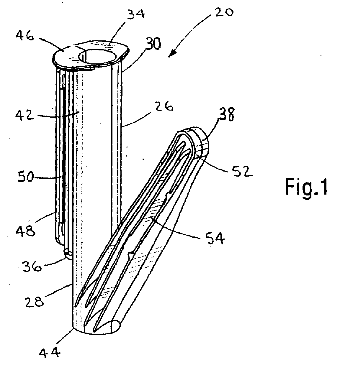
- FIGS. 8-12 show a 2-piece harness wrap application tool 20 molded from a suitable thermoplastic material.
- the tool is utilized to insert wires or cables 22 in a flexible harness wrap 24, as shown in FIGS. 8-12, such as the harness wrap disclosed in co-pending U.S. Ser. No, 10/243,821 the disclosure of which is incorporated by reference in its entirety.
- the tool 20 includes a first member 26 and a second member 28.
- the first member 26 has a first top end 30 and a first bottom end 32, with a first tab 34 extending from the first top end 30.
- the first tab 34 extends substantially perpendicular from the first top end 30.
- the first member 26 includes an extension member 36. connected thereto.
- the extension member 36 extends from near the first top end 30 toward the first bottom end 32.
- the first member 26 also includes a first nose portion 38 extending at an oblique angle from the first bottom end 32.
- the first nose portion 38 is bullet-shaped and has a plurality of ribs 40 along one side thereof. The first nose portion 38 eases transition of the flexible harness wrap 24 onto the wires or cables 22 to be secured therein.
- the second member 28 is hingedly connected to the first member 26.
- the second member 28 has a second top end 42 and a second bottom end 44, with a second tab 46 extending from the second top end 42.
- the second tab 46 extends substantially perpendicular from the second top end 42.
- the second member 28 includes a receiving member 48 connected thereto.
- the receiving member 48 extends from near the second top end 42 toward the second bottom end 44.
- the receiving member 48 has a retaining detent 50.
- the retaining detent 50 holds the first and second members 26, 28 together, and maintains frictional tension when the tool 20 is in the closed position.
- the detent 50 also provides user feedback that the tool 20 is fully closed. Further, the detent 50 provides resistance to inadvertent opening of the tool 20 when in the closed position.
- the retaining detent 50 extends substantially the length of the receiving member 48.
- the second member 28 also includes a second nose portion 52 extending at an oblique angle from the second bottom end 44.
- the second nose portion 52 is bullet-shaped and has a plurality of ribs 54 along one side thereof. The second nose portion 52 eases transition of the flexible harness 24 wrap onto the wires or cables 22 to be secured therein.
- the first and second members 26, 28 are movable from a first closed position, as shown in FIGS. 1-5, to a second, open position, as shown in FIGS. 6-8.
- the open position is at least 50 degrees from the closed position.
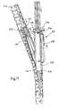
- FIG. 7 shows the tool moving from a fully closed position A to a partially open position B of at least 90 degrees to a fully open position C.
- the fully open position C is about 180 degrees from the fully closed position A.
- the present invention teaches that the open position is adjustable anywhere between 1 and 180 degrees from the closed position. As a result, the two-piece tool of the present invention does not require secondary metal accessories or springs.
- the first and second members 26, 28 are snapped together to form the harness wrap application tool 20.
- the tool 20 has a clam shell appearance.
- the tool 20 is moved to an open position at least 50 degrees from the closed position.
- the user can insert bundled cables or hoses as well as individual cables into the tool 20.
- the tool 20 is then closed to retain the cables 22 therein, as seen in FIG. 9.
- the first and second nose portions 38, 52 have been inserted into an opening in the flexible harness wrap 24.
- the user then engages the first and second tabs 34, 46 located on the top ends 30, 42 of the first and second members, 26, 28 respectively.
- FIG. 1 the first and second members 26, 28 are snapped together to form the harness wrap application tool 20.
- the tool 20 has a clam shell appearance.
- the tool 20 is moved to an open position at least 50 degrees from the closed position.
- the user can insert bundled cables or hoses as well as individual cables into the tool 20.
- the tool 20 is then closed to retain the cables 22 therein,
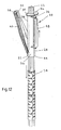
- the first and second nose portions 38, 52 of the tool 20 are moved through the flexible harness wrap 24 until the wires or cables 22 are laid therein, as shown in FIG. 12.
- the tool 20 can then be opened and removed from the wires or cables 22.
- the disclosed invention provides a harness wrap application tool for inserting wires or cables in a flexible harness wrap.
- the tool is movable from a first, closed position to a second, open position, with the open position being at least 50 degrees from the closed position.
- the above-described and illustrated embodiments and preferred embodiments of the invention are not an exhaustive listing of the forms such a harness wrap application tool in accordance with the invention might take; rather, they serve as exemplary and illustrative of embodiments of the invention as presently understood.
- a harness wrap application tool only movable between distinct positions from one to 180 degrees is contemplated to be within the scope of the invention. Many other forms of the invention are believed to exist.
Landscapes
- Electric Cable Installation (AREA)
- Installation Of Indoor Wiring (AREA)
- Details Of Indoor Wiring (AREA)
- Treatment Of Liquids With Adsorbents In General (AREA)
Abstract
Description
Claims (9)
- A tool for inserting wires or cables in a flexible harness wrap, the tool comprising:wherein the first and second members are moveable from a first, closed position to a second, open position, the open position being at least 50 degrees from the closed position.a first member having a first top end and a first bottom end, the first member having an extension member connected thereto and a first nose portion extending at an oblique angle from the first bottom end; anda second member connected to the first member, the second member having a second top end and a second bottom end, the second member having a receiving member connected thereto and a second nose portion extending at an oblique angle from the second bottom end,
- The tool of claim 1 wherein the first and/or second nose portion is bullet-shaped and has a plurality of ribs along one side thereof.
- The tool of claim 1 wherein the extension member extends from adjacent the first top end toward the first bottom end.
- The tool of claim 1 wherein the receiving member extends from adjacent the second top end toward the second bottom end.
- The tool of claim 1 wherein the receiving member has a retaining detent for frictionally retaining the extension member within the receiving member, and preferably wherein the retaining detent extends substantially the length of the receiving member.
- The tool of claim 1 wherein the first and/or second member has a respective first and/or second tab extending from the first and/or second top end, and preferably wherein the first and/or second tab extends substantially perpendicular from the respective first and/or second top end.
- A tool for inserting wires or cables in a flexible harness wrap, the tool comprising:wherein the first and second members are moveable from a first, closed position to a second, open position, the open position being adjustable between 1 and 180 degrees from the closed position.a first member having a first tope end and a first bottom end, the first member having an extension member connected thereto and a first nose portion extending at an oblique angle from the first bottom end; anda second member connected to the first member, the second member having a second top end and a second bottom end, the second member having a receiving member connected thereto and a second nose portion extending at an oblique angle from the second bottom end,
- A method of inserting wires or cables in a flexible harness wrap, the method comprising the steps of:providing a tool comprising a first member having an extension member connected thereto and a first nose portion extending at an oblique angle from a bottom end of the first member, and a second member connected to the first member, the second member having a receiving member connected thereto and a second nose portion extending at an oblique angle from a bottom end of the second member;opening the tool to an open position at least 50 degrees from a closed position;inserting the wires or cables into the tool;closing the tool to retain the wires or cables therein;inserting the first and second nose portions into an opening in the flexible harness wrap; andmoving the tool through the flexible harness wrap until the wires or cables are laid therein.
- A tool of claim 1 or method of claim 8 wherein the open position is at least 90 degrees from the closed position, and preferably wherein the open position is about 180 degrees from the closed position.
Applications Claiming Priority (2)
| Application Number | Priority Date | Filing Date | Title |
|---|---|---|---|
| US10/243,510 US6705002B1 (en) | 2002-09-13 | 2002-09-13 | Harness wrap application tool |
| US243510 | 2002-09-13 |
Publications (3)
| Publication Number | Publication Date |
|---|---|
| EP1398857A2 true EP1398857A2 (en) | 2004-03-17 |
| EP1398857A3 EP1398857A3 (en) | 2005-03-16 |
| EP1398857B1 EP1398857B1 (en) | 2007-07-18 |
Family
ID=31887808
Family Applications (1)
| Application Number | Title | Priority Date | Filing Date |
|---|---|---|---|
| EP03255617A Expired - Lifetime EP1398857B1 (en) | 2002-09-13 | 2003-09-09 | Harness wrap application tool |
Country Status (4)
| Country | Link |
|---|---|
| US (1) | US6705002B1 (en) |
| EP (1) | EP1398857B1 (en) |
| AT (1) | ATE367672T1 (en) |
| DE (1) | DE60314950T2 (en) |
Cited By (1)
| Publication number | Priority date | Publication date | Assignee | Title |
|---|---|---|---|---|
| EP1750897A4 (en) * | 2004-05-12 | 2007-04-25 | Richco Inc | Tool for installing flexible strand like material in a split harness wrap |
Families Citing this family (12)
| Publication number | Priority date | Publication date | Assignee | Title |
|---|---|---|---|---|
| US7076862B2 (en) * | 2003-08-06 | 2006-07-18 | International Business Machines Corporation | System, method, and apparatus for installing and removing flat cable with respect to a protective sleeve |
| JP4322186B2 (en) * | 2004-08-16 | 2009-08-26 | 矢崎総業株式会社 | Corrugated tube mounting jig |
| US7433571B2 (en) * | 2005-09-08 | 2008-10-07 | David Kendricks | Cable bundling and organizing system |
| US7861501B2 (en) * | 2008-05-10 | 2011-01-04 | Btx Technologies, Inc. | Method and apparatus for applying flexible sleeving |
| US8758348B2 (en) * | 2009-03-19 | 2014-06-24 | Figure 8 Surgical, Inc. | Systems and methods for sternum repair |
| US8460295B2 (en) | 2009-03-19 | 2013-06-11 | Figure 8 Surgical, Inc. | Systems and methods for sternum repair |
| US9398903B2 (en) | 2010-03-19 | 2016-07-26 | William T. MCCLELLAN | Knotless locking tissue fastening system and method |
| WO2012174562A1 (en) | 2011-06-17 | 2012-12-20 | Figure 8 Surgical, Inc. | Sternum band tensioner device, system and method |
| US9226680B1 (en) | 2013-02-12 | 2016-01-05 | David Kendricks | Patient electrode connectors for electrocardiograph monitoring system |
| US10800016B2 (en) | 2014-11-12 | 2020-10-13 | Abba Daddy Llc | Tool for installing protective and decorative tubing around wires |
| US10577730B1 (en) | 2015-12-21 | 2020-03-03 | Southwire Company, Llc | Cable assembly devices, systems, and methods |
| JP7115863B2 (en) * | 2018-02-13 | 2022-08-09 | 矢崎総業株式会社 | Wire insertion jig |
Family Cites Families (17)
| Publication number | Priority date | Publication date | Assignee | Title |
|---|---|---|---|---|
| US2743884A (en) | 1953-08-25 | 1956-05-01 | George E Briggs | Fish tape threader |
| US2946560A (en) * | 1958-05-19 | 1960-07-26 | Olaf G Ferm | Tool for guiding wires into conduits |
| US3866846A (en) | 1972-09-25 | 1975-02-18 | Ted C Dorsey | Wire wrap tool |
| DE3031987C2 (en) | 1980-08-25 | 1983-02-03 | Idento - Gesellschaft für industrielle Kennzeichnung mbH, 6074 Rödermark | Marking device for electrical conductors |
| US4951923A (en) | 1989-09-14 | 1990-08-28 | Couture Richard P | Electrical wire guide temporarily placed in an electrical wiring junction box to protect the insulation of electrical wires being guided and pulled into this box and through a conduit to the next junction box |
| US5067843A (en) | 1989-09-25 | 1991-11-26 | Nova Wallace B | Pulling attachment for flexible conduit |
| US5265326A (en) * | 1991-11-20 | 1993-11-30 | Scribner Herbert H | Wire insertion hand tool for the insertion of wires, or similar strand-like material, within a wire containing duct |
| JP3410516B2 (en) * | 1993-07-20 | 2003-05-26 | 株式会社オールテック | Wire insertion jig |
| CN1075619C (en) * | 1996-09-03 | 2001-11-28 | 住友电装株式会社 | Corrugated tube and automatic wire-loading device therefor |
| US5884901A (en) | 1997-03-17 | 1999-03-23 | Schilling; Daniel R. | Apparatus for threading electrical wires into flexible conduit |
| US5906357A (en) | 1998-07-10 | 1999-05-25 | Munson, Sr.; Karl Alvin | Conduit torpedo construction |
| DE69917742T2 (en) | 1999-03-02 | 2004-10-21 | Richco Italia S R L | Device for inserting wires bez. Tubes in a tubular, flexible envelope with overlapping edges that can be opened |
| JP2001054216A (en) * | 1999-08-09 | 2001-02-23 | Sumitomo Wiring Syst Ltd | Tool for inserting wire harness to through-hole |
| FR2799878B1 (en) * | 1999-10-13 | 2001-12-21 | Henri Bigot | HARNESS FOR WIRE HARNESS |
| CN2434811Y (en) * | 2000-05-10 | 2001-06-13 | 美星国际有限公司 | Lead-in clips and wire protectors |
| US6302379B1 (en) | 2000-05-11 | 2001-10-16 | Paul A. Walters | Device for facilitating threading of electrical cable through a pipe |
| CN2616495Y (en) * | 2002-03-25 | 2004-05-19 | 胡国海 | Spool elastic protecting sleeve |
-
2002
- 2002-09-13 US US10/243,510 patent/US6705002B1/en not_active Expired - Fee Related
-
2003
- 2003-09-09 DE DE60314950T patent/DE60314950T2/en not_active Expired - Lifetime
- 2003-09-09 EP EP03255617A patent/EP1398857B1/en not_active Expired - Lifetime
- 2003-09-09 AT AT03255617T patent/ATE367672T1/en not_active IP Right Cessation
Cited By (1)
| Publication number | Priority date | Publication date | Assignee | Title |
|---|---|---|---|---|
| EP1750897A4 (en) * | 2004-05-12 | 2007-04-25 | Richco Inc | Tool for installing flexible strand like material in a split harness wrap |
Also Published As
| Publication number | Publication date |
|---|---|
| US20040049913A1 (en) | 2004-03-18 |
| DE60314950D1 (en) | 2007-08-30 |
| EP1398857A3 (en) | 2005-03-16 |
| US6705002B1 (en) | 2004-03-16 |
| DE60314950T2 (en) | 2008-04-03 |
| ATE367672T1 (en) | 2007-08-15 |
| EP1398857B1 (en) | 2007-07-18 |
Similar Documents
| Publication | Publication Date | Title |
|---|---|---|
| US6705002B1 (en) | Harness wrap application tool | |
| US6059484A (en) | Guide wire introducer assembly with guide wire grip and release means | |
| US5555607A (en) | Retaining device | |
| US4183603A (en) | Extension cord lock | |
| DE102004010337B4 (en) | Fixing member and connector | |
| WO1998025329B1 (en) | Method of storing bundled items | |
| EP1464306A3 (en) | Implant for the intervertebral space | |
| EP0735394A2 (en) | Optical fibre clamping device | |
| EP0831348A3 (en) | Optical connector | |
| EP0884738B1 (en) | Assembly device for a wiring harness | |
| EP0972324B1 (en) | Tool and method for sheathing of cables | |
| CA2327687C (en) | Adjustable retainer for electrical cords | |
| JP3410516B2 (en) | Wire insertion jig | |
| WO2003084021A8 (en) | Cable sealing cover including stress relief | |
| US5558546A (en) | Electrical wedge connector with preinstallment interconnector | |
| JP3609806B2 (en) | Long body insertion jig | |
| NO20004207D0 (en) | A method of making a fiber optic male connector | |
| US5887855A (en) | Electronics installation hand tool system | |
| JP3371716B2 (en) | Corrugated tube fitting | |
| JPH07107636A (en) | Linear material insertion jig | |
| JP2022124866A (en) | Cable protective guide device and tubular member | |
| JP2588348Y2 (en) | L-shaped bent cover jig | |
| WO2005123328A2 (en) | Tool for installing flexible strand like material in a split harness wrap | |
| KR101985959B1 (en) | Tube for protecting wire harness | |
| CA2243749C (en) | Fixture and method for compressing wire mesh grip to facilitate installation on cables |
Legal Events
| Date | Code | Title | Description |
|---|---|---|---|
| PUAI | Public reference made under article 153(3) epc to a published international application that has entered the european phase |
Free format text: ORIGINAL CODE: 0009012 |
|
| AK | Designated contracting states |
Kind code of ref document: A2 Designated state(s): AT BE BG CH CY CZ DE DK EE ES FI FR GB GR HU IE IT LI LU MC NL PT RO SE SI SK TR |
|
| AX | Request for extension of the european patent |
Extension state: AL LT LV MK |
|
| PUAL | Search report despatched |
Free format text: ORIGINAL CODE: 0009013 |
|
| AK | Designated contracting states |
Kind code of ref document: A3 Designated state(s): AT BE BG CH CY CZ DE DK EE ES FI FR GB GR HU IE IT LI LU MC NL PT RO SE SI SK TR |
|
| AX | Request for extension of the european patent |
Extension state: AL LT LV MK |
|
| 17P | Request for examination filed |
Effective date: 20050907 |
|
| AKX | Designation fees paid |
Designated state(s): AT BE BG CH CY CZ DE DK EE ES FI FR GB GR HU IE IT LI LU MC NL PT RO SE SI SK TR |
|
| GRAP | Despatch of communication of intention to grant a patent |
Free format text: ORIGINAL CODE: EPIDOSNIGR1 |
|
| GRAS | Grant fee paid |
Free format text: ORIGINAL CODE: EPIDOSNIGR3 |
|
| GRAA | (expected) grant |
Free format text: ORIGINAL CODE: 0009210 |
|
| AK | Designated contracting states |
Kind code of ref document: B1 Designated state(s): AT BE BG CH CY CZ DE DK EE ES FI FR GB GR HU IE IT LI LU MC NL PT RO SE SI SK TR |
|
| REG | Reference to a national code |
Ref country code: GB Ref legal event code: FG4D |
|
| REG | Reference to a national code |
Ref country code: CH Ref legal event code: EP |
|
| REF | Corresponds to: |
Ref document number: 60314950 Country of ref document: DE Date of ref document: 20070830 Kind code of ref document: P |
|
| REG | Reference to a national code |
Ref country code: IE Ref legal event code: FG4D |
|
| ET | Fr: translation filed | ||
| PG25 | Lapsed in a contracting state [announced via postgrant information from national office to epo] |
Ref country code: NL Free format text: LAPSE BECAUSE OF FAILURE TO SUBMIT A TRANSLATION OF THE DESCRIPTION OR TO PAY THE FEE WITHIN THE PRESCRIBED TIME-LIMIT Effective date: 20070718 Ref country code: FI Free format text: LAPSE BECAUSE OF FAILURE TO SUBMIT A TRANSLATION OF THE DESCRIPTION OR TO PAY THE FEE WITHIN THE PRESCRIBED TIME-LIMIT Effective date: 20070718 Ref country code: ES Free format text: LAPSE BECAUSE OF FAILURE TO SUBMIT A TRANSLATION OF THE DESCRIPTION OR TO PAY THE FEE WITHIN THE PRESCRIBED TIME-LIMIT Effective date: 20071029 Ref country code: PT Free format text: LAPSE BECAUSE OF FAILURE TO SUBMIT A TRANSLATION OF THE DESCRIPTION OR TO PAY THE FEE WITHIN THE PRESCRIBED TIME-LIMIT Effective date: 20071218 Ref country code: BG Free format text: LAPSE BECAUSE OF FAILURE TO SUBMIT A TRANSLATION OF THE DESCRIPTION OR TO PAY THE FEE WITHIN THE PRESCRIBED TIME-LIMIT Effective date: 20071018 |
|
| REG | Reference to a national code |
Ref country code: CH Ref legal event code: PL |
|
| NLV1 | Nl: lapsed or annulled due to failure to fulfill the requirements of art. 29p and 29m of the patents act | ||
| PG25 | Lapsed in a contracting state [announced via postgrant information from national office to epo] |
Ref country code: AT Free format text: LAPSE BECAUSE OF FAILURE TO SUBMIT A TRANSLATION OF THE DESCRIPTION OR TO PAY THE FEE WITHIN THE PRESCRIBED TIME-LIMIT Effective date: 20070718 Ref country code: CH Free format text: LAPSE BECAUSE OF FAILURE TO SUBMIT A TRANSLATION OF THE DESCRIPTION OR TO PAY THE FEE WITHIN THE PRESCRIBED TIME-LIMIT Effective date: 20070718 Ref country code: LI Free format text: LAPSE BECAUSE OF FAILURE TO SUBMIT A TRANSLATION OF THE DESCRIPTION OR TO PAY THE FEE WITHIN THE PRESCRIBED TIME-LIMIT Effective date: 20070718 |
|
| PG25 | Lapsed in a contracting state [announced via postgrant information from national office to epo] |
Ref country code: BE Free format text: LAPSE BECAUSE OF FAILURE TO SUBMIT A TRANSLATION OF THE DESCRIPTION OR TO PAY THE FEE WITHIN THE PRESCRIBED TIME-LIMIT Effective date: 20070718 |
|
| PG25 | Lapsed in a contracting state [announced via postgrant information from national office to epo] |
Ref country code: DK Free format text: LAPSE BECAUSE OF FAILURE TO SUBMIT A TRANSLATION OF THE DESCRIPTION OR TO PAY THE FEE WITHIN THE PRESCRIBED TIME-LIMIT Effective date: 20070718 Ref country code: GR Free format text: LAPSE BECAUSE OF FAILURE TO SUBMIT A TRANSLATION OF THE DESCRIPTION OR TO PAY THE FEE WITHIN THE PRESCRIBED TIME-LIMIT Effective date: 20071019 Ref country code: MC Free format text: LAPSE BECAUSE OF NON-PAYMENT OF DUE FEES Effective date: 20070930 |
|
| PLBE | No opposition filed within time limit |
Free format text: ORIGINAL CODE: 0009261 |
|
| STAA | Information on the status of an ep patent application or granted ep patent |
Free format text: STATUS: NO OPPOSITION FILED WITHIN TIME LIMIT |
|
| PG25 | Lapsed in a contracting state [announced via postgrant information from national office to epo] |
Ref country code: SK Free format text: LAPSE BECAUSE OF FAILURE TO SUBMIT A TRANSLATION OF THE DESCRIPTION OR TO PAY THE FEE WITHIN THE PRESCRIBED TIME-LIMIT Effective date: 20070718 Ref country code: CZ Free format text: LAPSE BECAUSE OF FAILURE TO SUBMIT A TRANSLATION OF THE DESCRIPTION OR TO PAY THE FEE WITHIN THE PRESCRIBED TIME-LIMIT Effective date: 20070718 |
|
| 26N | No opposition filed |
Effective date: 20080421 |
|
| PG25 | Lapsed in a contracting state [announced via postgrant information from national office to epo] |
Ref country code: RO Free format text: LAPSE BECAUSE OF FAILURE TO SUBMIT A TRANSLATION OF THE DESCRIPTION OR TO PAY THE FEE WITHIN THE PRESCRIBED TIME-LIMIT Effective date: 20070718 Ref country code: SE Free format text: LAPSE BECAUSE OF FAILURE TO SUBMIT A TRANSLATION OF THE DESCRIPTION OR TO PAY THE FEE WITHIN THE PRESCRIBED TIME-LIMIT Effective date: 20071018 |
|
| PG25 | Lapsed in a contracting state [announced via postgrant information from national office to epo] |
Ref country code: IE Free format text: LAPSE BECAUSE OF NON-PAYMENT OF DUE FEES Effective date: 20070910 |
|
| PG25 | Lapsed in a contracting state [announced via postgrant information from national office to epo] |
Ref country code: EE Free format text: LAPSE BECAUSE OF FAILURE TO SUBMIT A TRANSLATION OF THE DESCRIPTION OR TO PAY THE FEE WITHIN THE PRESCRIBED TIME-LIMIT Effective date: 20070718 |
|
| PG25 | Lapsed in a contracting state [announced via postgrant information from national office to epo] |
Ref country code: SI Free format text: LAPSE BECAUSE OF FAILURE TO SUBMIT A TRANSLATION OF THE DESCRIPTION OR TO PAY THE FEE WITHIN THE PRESCRIBED TIME-LIMIT Effective date: 20070718 |
|
| PG25 | Lapsed in a contracting state [announced via postgrant information from national office to epo] |
Ref country code: CY Free format text: LAPSE BECAUSE OF FAILURE TO SUBMIT A TRANSLATION OF THE DESCRIPTION OR TO PAY THE FEE WITHIN THE PRESCRIBED TIME-LIMIT Effective date: 20070718 |
|
| PG25 | Lapsed in a contracting state [announced via postgrant information from national office to epo] |
Ref country code: LU Free format text: LAPSE BECAUSE OF NON-PAYMENT OF DUE FEES Effective date: 20070909 |
|
| PG25 | Lapsed in a contracting state [announced via postgrant information from national office to epo] |
Ref country code: HU Free format text: LAPSE BECAUSE OF FAILURE TO SUBMIT A TRANSLATION OF THE DESCRIPTION OR TO PAY THE FEE WITHIN THE PRESCRIBED TIME-LIMIT Effective date: 20080119 Ref country code: TR Free format text: LAPSE BECAUSE OF FAILURE TO SUBMIT A TRANSLATION OF THE DESCRIPTION OR TO PAY THE FEE WITHIN THE PRESCRIBED TIME-LIMIT Effective date: 20070718 |
|
| PGFP | Annual fee paid to national office [announced via postgrant information from national office to epo] |
Ref country code: FR Payment date: 20100921 Year of fee payment: 8 |
|
| PGFP | Annual fee paid to national office [announced via postgrant information from national office to epo] |
Ref country code: GB Payment date: 20100908 Year of fee payment: 8 |
|
| PG25 | Lapsed in a contracting state [announced via postgrant information from national office to epo] |
Ref country code: IT Free format text: LAPSE BECAUSE OF NON-PAYMENT OF DUE FEES Effective date: 20070930 |
|
| PGFP | Annual fee paid to national office [announced via postgrant information from national office to epo] |
Ref country code: DE Payment date: 20100901 Year of fee payment: 8 |
|
| GBPC | Gb: european patent ceased through non-payment of renewal fee |
Effective date: 20110909 |
|
| REG | Reference to a national code |
Ref country code: FR Ref legal event code: ST Effective date: 20120531 |
|
| REG | Reference to a national code |
Ref country code: DE Ref legal event code: R119 Ref document number: 60314950 Country of ref document: DE Effective date: 20120403 |
|
| PG25 | Lapsed in a contracting state [announced via postgrant information from national office to epo] |
Ref country code: DE Free format text: LAPSE BECAUSE OF NON-PAYMENT OF DUE FEES Effective date: 20120403 |
|
| PG25 | Lapsed in a contracting state [announced via postgrant information from national office to epo] |
Ref country code: FR Free format text: LAPSE BECAUSE OF NON-PAYMENT OF DUE FEES Effective date: 20110930 Ref country code: GB Free format text: LAPSE BECAUSE OF NON-PAYMENT OF DUE FEES Effective date: 20110909 |