EP1398843A2 - Fuel cell system - Google Patents
Fuel cell system Download PDFInfo
- Publication number
- EP1398843A2 EP1398843A2 EP03020109A EP03020109A EP1398843A2 EP 1398843 A2 EP1398843 A2 EP 1398843A2 EP 03020109 A EP03020109 A EP 03020109A EP 03020109 A EP03020109 A EP 03020109A EP 1398843 A2 EP1398843 A2 EP 1398843A2
- Authority
- EP
- European Patent Office
- Prior art keywords
- fuel cell
- combustor
- gas
- reformer
- air
- Prior art date
- Legal status (The legal status is an assumption and is not a legal conclusion. Google has not performed a legal analysis and makes no representation as to the accuracy of the status listed.)
- Withdrawn
Links
Images


Classifications
-
- H—ELECTRICITY
- H01—ELECTRIC ELEMENTS
- H01M—PROCESSES OR MEANS, e.g. BATTERIES, FOR THE DIRECT CONVERSION OF CHEMICAL ENERGY INTO ELECTRICAL ENERGY
- H01M8/00—Fuel cells; Manufacture thereof
- H01M8/02—Details
- H01M8/0202—Collectors; Separators, e.g. bipolar separators; Interconnectors
- H01M8/0267—Collectors; Separators, e.g. bipolar separators; Interconnectors having heating or cooling means, e.g. heaters or coolant flow channels
-
- H—ELECTRICITY
- H01—ELECTRIC ELEMENTS
- H01M—PROCESSES OR MEANS, e.g. BATTERIES, FOR THE DIRECT CONVERSION OF CHEMICAL ENERGY INTO ELECTRICAL ENERGY
- H01M8/00—Fuel cells; Manufacture thereof
- H01M8/04—Auxiliary arrangements, e.g. for control of pressure or for circulation of fluids
- H01M8/04082—Arrangements for control of reactant parameters, e.g. pressure or concentration
- H01M8/04089—Arrangements for control of reactant parameters, e.g. pressure or concentration of gaseous reactants
- H01M8/04097—Arrangements for control of reactant parameters, e.g. pressure or concentration of gaseous reactants with recycling of the reactants
-
- H—ELECTRICITY
- H01—ELECTRIC ELEMENTS
- H01M—PROCESSES OR MEANS, e.g. BATTERIES, FOR THE DIRECT CONVERSION OF CHEMICAL ENERGY INTO ELECTRICAL ENERGY
- H01M8/00—Fuel cells; Manufacture thereof
- H01M8/04—Auxiliary arrangements, e.g. for control of pressure or for circulation of fluids
- H01M8/04223—Auxiliary arrangements, e.g. for control of pressure or for circulation of fluids during start-up or shut-down; Depolarisation or activation, e.g. purging; Means for short-circuiting defective fuel cells
- H01M8/04228—Auxiliary arrangements, e.g. for control of pressure or for circulation of fluids during start-up or shut-down; Depolarisation or activation, e.g. purging; Means for short-circuiting defective fuel cells during shut-down
-
- H—ELECTRICITY
- H01—ELECTRIC ELEMENTS
- H01M—PROCESSES OR MEANS, e.g. BATTERIES, FOR THE DIRECT CONVERSION OF CHEMICAL ENERGY INTO ELECTRICAL ENERGY
- H01M8/00—Fuel cells; Manufacture thereof
- H01M8/04—Auxiliary arrangements, e.g. for control of pressure or for circulation of fluids
- H01M8/04298—Processes for controlling fuel cells or fuel cell systems
- H01M8/043—Processes for controlling fuel cells or fuel cell systems applied during specific periods
- H01M8/04303—Processes for controlling fuel cells or fuel cell systems applied during specific periods applied during shut-down
-
- H—ELECTRICITY
- H01—ELECTRIC ELEMENTS
- H01M—PROCESSES OR MEANS, e.g. BATTERIES, FOR THE DIRECT CONVERSION OF CHEMICAL ENERGY INTO ELECTRICAL ENERGY
- H01M8/00—Fuel cells; Manufacture thereof
- H01M8/06—Combination of fuel cells with means for production of reactants or for treatment of residues
- H01M8/0606—Combination of fuel cells with means for production of reactants or for treatment of residues with means for production of gaseous reactants
- H01M8/0612—Combination of fuel cells with means for production of reactants or for treatment of residues with means for production of gaseous reactants from carbon-containing material
-
- Y—GENERAL TAGGING OF NEW TECHNOLOGICAL DEVELOPMENTS; GENERAL TAGGING OF CROSS-SECTIONAL TECHNOLOGIES SPANNING OVER SEVERAL SECTIONS OF THE IPC; TECHNICAL SUBJECTS COVERED BY FORMER USPC CROSS-REFERENCE ART COLLECTIONS [XRACs] AND DIGESTS
- Y02—TECHNOLOGIES OR APPLICATIONS FOR MITIGATION OR ADAPTATION AGAINST CLIMATE CHANGE
- Y02E—REDUCTION OF GREENHOUSE GAS [GHG] EMISSIONS, RELATED TO ENERGY GENERATION, TRANSMISSION OR DISTRIBUTION
- Y02E60/00—Enabling technologies; Technologies with a potential or indirect contribution to GHG emissions mitigation
- Y02E60/30—Hydrogen technology
- Y02E60/50—Fuel cells
Definitions
- This invention relates to a fuel cell system comprising a reformer producing reformate gas and a fuel cell stack using the reformate gas.
- a technique for preventing oxidization of the reforming catalyst and adhesion of water to the surface of the reforming catalyst discloses a technique of drying the surface of the reforming catalyst and removing oxygen from the reformer by prolonged purging with nitrogen. The fuel cell system is shut down after the prolonged purging operation. Furthermore this technique requires a device supplying hydrogen gas to the reformer to reduce the oxidized reforming catalyst.
- Tokkai-Sho 63-44934 is not suitable for use in vehicle-mounted fuel cell systems as it requires a nitrogen cylinder and a hydrogen cylinder.
- the prior art technique disclosed in Tokkai 2000-36314 requires a structure having extremely air-tight characteristics for the reformer due to the residual hydrogen in the reformer after the operation of the fuel cell system is stopped.
- this invention provides a fuel cell system having a reformer for generating a reformate gas containing hydrogen from fuel and water/air, a fuel cell stack for generating electric power as a result of supply of reformate gas, a combustor for combusting combustible gas introduced into the combustor, a passage for connecting the reformer and the fuel cell stack, and a passage for connecting the fuel cell stack and the combustor.
- the fuel cell system comprises a recirculation passage connecting the reformer and the combustor so as to allow a flow of the gas discharged from the combustor to the reformer; a recirculation device for recirculating gas discharged from the combustor through the recirculation passage and the reformer; a supply device for controlling a supply of fuel and water/ air to the reformer; a device for selecting an operation mode of the fuel cell system from a group including a normal operation mode in which the fuel cell stack performs power generation and a stop mode in which the fuel cell stack does not perform power generation; and a controller for controlling the supply device and the recirculation device in response to the operation mode of the fuel cell system.
- the controller functions to control the supply device to stop the supply of fuel and water/air to the reformer in the stop mode; and subsequently control the recirculation device to recirculate the discharged gas from the combustor through the recirculation passage and the reformer.
- this invention provides a control method for controlling a fuel cell system, the fuel cell system having a reformer for generating a reformate gas containing hydrogen from fuel and water/ air, a fuel cell stack for generating electric power as a result of supply of reformate gas, a combustor for combusting combustible gas introduced into the combustor, a passage for connecting the reformer and the fuel cell stack, a passage for connecting the fuel cell stack and the combustor, and a recirculation device for recirculating gas discharged from the combustor through the recirculation passage and the reformer.
- a reformer for generating a reformate gas containing hydrogen from fuel and water/ air
- a fuel cell stack for generating electric power as a result of supply of reformate gas
- a combustor for combusting combustible gas introduced into the combustor
- a passage for connecting the reformer and the fuel cell stack a passage for connecting the fuel cell stack and the combustor
- the method comprises the steps of selecting an operation mode of the fuel cell system from a group including a normal operation mode in which the fuel cell stack performs power generation and a stop mode in which the fuel cell stack does not perform power generation; and stopping the supply of fuel and water/ air to the reformer in the stop mode; and subsequently recirculating the discharged gas from the combustor through the recirculation passage and the reformer.
- FIG. 1 is a schematic diagram of a fuel cell system showing a first embodiment of the invention.
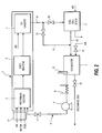
- FIG. 2 is a schematic diagram of a fuel cell system showing a second embodiment of the invention.
- FIG. 3 is a schematic diagram of a control device for a fuel cell system as shown in FIG. 2.
- FIG. 4 is a flowchart showing a control routine executed by a controller as shown in FIG. 2.
- FIG. 5 is a schematic diagram of a fuel cell system showing a third embodiment of the invention.
- a fuel cell system comprises a reformer 1 which generates a reformate gas bearing hydrogen from air and/or water and a fuel such as a hydrocarbon, a fuel cell stack 2 for generating power using the reformate gas and air, a combustor 3 for combusting unused hydrogen discharged from the fuel cell stack 2, and a recirculation passage 4 for supplying discharge gas from the combustor 3 to the reformer 1.
- a reformer 1 which generates a reformate gas bearing hydrogen from air and/or water and a fuel such as a hydrocarbon
- a fuel cell stack 2 for generating power using the reformate gas and air
- a combustor 3 for combusting unused hydrogen discharged from the fuel cell stack 2
- a recirculation passage 4 for supplying discharge gas from the combustor 3 to the reformer 1.
- the reformer 1 is provided with a reforming section 5, a shift reactor 6 and a carbon monoxide selective oxidizer 7.
- the reforming section 5 is supplied with air and/or water and fuel to generate reformate gas.
- the resulting reformate gas flows into the shift reactor 6.
- the shift reactor 6 produces hydrogen and carbon dioxide (CO 2 ) by reacting water and carbon monoxide (CO) in the reformate gas to remove CO.
- CO carbon monoxide
- the carbon monoxide selective oxidizer 7 oxidizes residual carbon monoxide in the reformate gas using supplied air to remove CO.
- the resulting reformate gas flows into the fuel cell stack 2 through a passage 41 connecting the reformer 1 and the fuel cell stack 2.
- the fuel cell stack 2 is supplied with air and reformate gas from the carbon monoxide selective reactor 7 in the reformer 1 and generates electrical power using electrochemical reactions between hydrogen and oxygen.
- the discharged gas from the fuel cell stack 2 containing unused hydrogen is supplied to the combustor 3 through the passage 42 connecting the combustor 3 and the fuel cell stack 2.
- Discharge air is discharged from the fuel cell stack 2 to the outside without modification.
- the combustor 3 performs combustion of unused hydrogen from the fuel cell stack 2 using air.
- a discharge valve 10 is provided in the discharge line allowing discharge gas (in other words, combustion gas) to flow from the combustor 3 to the outside. The discharge valve 10 is closed when the fuel cell 2 is not generating power and is open when the fuel cell stack 2 is generating power.
- the gas discharged from the combustor 3 is supplied to the recirculation passage 4 which allows the flow of the gas discharged from the combustor 3 to the reformer 1. In this manner, the gas discharged from the combustor 3 becomes recirculation gas which is circulated in the gas passage in the fuel cell system from the combustor 3 through the reformer 1.
- the recirculation passage 4 connects the inlet of the reforming section 5 of the reformer 1 and the outlet of the combustor 3 and supplies discharge gas from the combustor 3 to the reforming section 5 when power generation in the fuel cell stack 2 is stopped.
- a circulation control valve 11, a recirculation blower 9 and a cooler 8 are disposed in the recirculation passage 4. The circulation control valve 11 is opened when power generation is stopped.
- the recirculation blower 9 and cooler 8 are operated after power generation in the fuel cell stack 2 is stopped.
- the cooler 8 cools the recirculation gas emitted from the combustor 3 to remove water vapor.
- the recirculation blower 9 generates the flow of the recirculation gas.
- the recirculation blower 9 operates when power generation operations in the fuel cell stack 2 are stopped and transfers recirculation gas from which a part of moisture has been removed by the action of the cooler 8 to the reforming section 5 of the reformer 1.
- the circulation control valve 11 is closed during power generation operations in the fuel cell stack 2 and is opened in order to connect the recirculation passage 4 when power generation operations in the fuel cell stack 2 are stopped.
- the operation of the fuel cell stack 2, the discharge valve 10, the circulation control valve 11, the recirculation blower 9 and the cooler 8 are controlled by a controller 15.
- the controller 15 comprises a microcomputer having a central processing unit (CPU) for running programs, read-only memory (ROM) for storing programs and data, random access memory (RAM) for temporarily storing data acquired as computing results from the CPU, and an input/output interface (I/O interface).
- the controller 15 may comprise a plurality of microcomputers.
- Reformate gas containing hydrogen is generated in the reforming section 5 of the reformer 1 by reformate reactions between supplied fuel and air/water (at least one of air and water).
- the reformate reactions in the reforming section 5 are autothermal reformate reactions occurring simultaneously with oxidizing reformate reactions and steam reformate reactions.
- the steam reformate reaction is an endothermic reaction as expressed in Equation (1).
- the fuel cell stack 2 is supplied with air and reformate gas and generates electrical power using electro-chemical reactions.
- the combustor 3 combusts residual hydrogen in the discharge gas from the fuel cell stack 2 using supplied air.
- the supply of water and fuel to the reformer 1 is stopped and the discharge valve 10 is closed.
- the circulation control valve 11 is opened, i.e. the recirculation passage 4 is opened, and the recirculation blower 9 and the cooler 8 are operated.
- the combustible gas in each reactor is removed by combustion.
- the recirculation gas may be circulated in a predetermined time period until the combustion of all combustible gas in the recirculation gas is completed, where the predetermined time period can be experimentally determined.
- Water produced by the conversion reaction is separated and removed by the cooler 8 while the gas is recirculating.
- the humidity is gradually reduced by gradually removing moisture (water vapor) in the recirculation gas supplied to the reformer 1.
- the conversion reaction in the combustor 3 occurs continuously as a result of the operation of the recirculation blower 9.
- FIG. 2 to FIG. 4 a second embodiment of a fuel cell system applying this invention will be described.
- the combustor 3 is temperature-controlled and the fuel cell stack 2 is separated from the route taken by the recirculation gas.
- Those components which are the same or similar to FIG. 1 are designated by the same reference numerals and additional description will be omitted.
- an air valve 13 and a temperature sensor 12 are provided for the combustor 3.
- the air valve 13 regulates the supply amount of air for combustion.
- the temperature sensor 12 detects the temperature of the combustor 3 and inputs a temperature signal to the controller 15.
- the opening of the air valve 13 is controlled in response to commands from the controller 15.
- the air valve 13 is gradually opened when the temperature of the combustor 3 falls below a maximum permitted temperature and gradually closed when the temperature exceeds a maximum permitted temperature.
- the controller 15 determines that the combustion of combustible gas in the combustor 3 is completed and completely closes the air valve 13.
- a bypass passage 14 bypasses the fuel cell stack 2 and supplies gas from the reformer 1 directly to the combustor 3.
- the bypass passage 14 branches from the passage 41 connecting the reformer 1 and the fuel cell stack 2 and is connected to a passage 42 connecting the combustor 3 and the fuel cell stack 2.
- a bypass control valve 32 is provided immediately upstream of the inlet for the fuel cell stack 2 and a bypass control valve 31 is provided in the bypass passage 14. This allows the direction of gas flow from the reformer 1 to be directed to the bypass passage 14 or to the fuel cell stack 2.
- the bypass control valves 31, 32 may be integrated into a single directional control valve for controlling the direction of gas flow.
- the controller 15 closes the bypass control valve 31 and opens the bypass control valve 32 during normal operation of the fuel cell stack 2. When the fuel cell stack 2 is not operated, the controller 15 opens the bypass control valve 31 and closes the bypass control valve 32.
- a temperature signal from the temperature sensor 12 in the combustor 3 and an operation mode signal for the fuel cell system are inputted from the operation control device 16 to the controller 15.
- the operation control device 16 may comprise a control panel used by a user of the fuel cell system. The user can select the operation mode (normal operation mode or operation-stop mode) of the fuel cell system using the operation control device 16. In the normal operation mode, the fuel cell stack performs power generation. In the operation-stop mode, the fuel cell stack does not perform power generation and the fuel cell system performs a shutdown operation. The user who does not intend to use the fuel cell system may select the operation-stop mode. Further, the operation control device 16 may be a switch having an ON position corresponding to the normal-operation mode and an OFF position of corresponding to the operation-stop mode. In this case, the controller 15 detects the ON/OFF position of the switch.
- the controller 15 controls the air valve 13, the discharge valve 10, the circulation control valve 11, the bypass control valves 31, 32, and the supply device 17 which controls the supply of air, water and fuel to the reformer 1 in response to the operation mode.
- the supply device 17 may comprise a valve for controlling the flow amount of air supply to the reformer 1, a valve for controlling the flow amount of water supplied to the reformer 1 and a valve for controlling the flow amount of fuel supplied to the reformer 1. If the reforming section 5 performs only one of the oxidizing reformate reaction and steam reformate reaction, it is not necessary for the supply device 17 to have both of the valve for controlling the flow amount of air supply and valve for controlling the flow amount of water.
- the flowchart shown in FIG. 4 shows a control routine executed by the controller 15 when the operation-stop mode is selected. Referring to the flowchart shown in FIG. 4, control for the fuel cell system in the operation-stop mode will be described.
- steps S1 to S4 show preparatory steps for stopping operation of the fuel cell system.
- Steps S5, S6, S11 are temperature control steps for the combustor 3. Temperature control in the combustor 3 is used in order to process combustible gas present in the recirculation gas without damaging the combustor 3.
- Steps S7 to S10 determine whether or not uncombusted components remain in the recirculation gas.
- Steps S12 and S 13 are final processing steps.
- step S1 the supply device 17 is controlled to stop the supply of air and/or water and fuel to the reformer 1.
- step S2 the bypass control valve 31 and the circulation control valve 11 are opened.
- step S3 the discharge valve 10 and the bypass control valve 32 are closed.
- step S4 the recirculation blower 9 and the cooler 8 are operated.
- reformate gas from the reformer 1 does not flow into the fuel cell stack 2 but is supplied to the combustor 3 via the bypass passage 14.
- Recirculation gas is then supplied to the reformer 1 via the cooler 8, the recirculation blower 9 and the circulation control valve 11 in the recirculation passage 4.
- the combustor 3 converts recirculation gas to carbon dioxide.
- the cooler 8 removes water vapor contained in the recirculation gas of the recirculation passage 4.
- the temperature T of the combustor 3 is read by using the temperature sensor 12 and is stored in the RAM.
- the routine progresses to the step S7.
- the routine progresses to the step S11.
- the air valve 13 is closed by a predetermined amount, and then the routine returns to the step S5.
- the supplied air amount is decreased by decreasing the opening of the air valve 13 so as to reduce the level of combustion in the combustor 3.
- the temperature of the combustor 3 exceeds the maximum permitted temperature, the operation of the combustor 3 undergoes an abnormality.
- the combustion temperature of the combustor 3 increases in response to an increase in the supplied air amount to the combustor 3. This enables a judgment about the existence/ absence of combustible components in the recirculation gas in an indirect manner. After the combustion of all combustible gas is completed, resulting in the absence of the combustible components in the recirculation gas, the temperature of the combustor 3 detected by the temperature sensor 14 decreases.
- the opening of the air valve 13 is increased by a predetermined amount and the supplied air amount to the combustor 3 is increased in order to promote combustion in the combustor 3.
- the latest data of temperature T (which has been read in the step S5 or S9) is assigned to a variable Tbefore as a previous temperature.
- the current temperature of the combustor 3 is read and is stored in the RAM.
- it is determined whether or not the current temperature T is higher than the previous temperature Tbefore.
- the routine returns to the step S6 because there are uncombusted components in the circulation gas.
- the routine returns to the step S12 because there are no uncombusted components in the recirculation gas.
- step S12 the air valve 13 is completely closed, setting the opening of the air valve 13 to zero.
- step S 13 the operation of the recirculation blower 9 and the cooler 8 is stopped. At this point, all operation of the fuel cell system has been stopped.
- the fuel cell stack 2 is separated from the flow of recirculated gas. As a result, after stopping the power generation, there is the possibility that residual moisture or oxygen will reduce the performance of the electrode catalyst in the fuel cell stack 2.
- FIG. 5 shows a third embodiment of a fuel cell system applying this invention.
- oxidation of combustible gas is performed in the respective oxidation reactors of the reformer 1 in addition to the combustor 3.
- Those components which are the same as those in FIG. 1 and FIG. 2 are designated by the same reference numerals and additional description is omitted.
- Air and recirculation gas are supplied to the reforming section 5 and carbon monoxide selective oxidizer 7 of the reformer 1 after the operation of the fuel cell stack is stopped.
- Air valves 18, 19 are provided in the air supply passages to the carbon monoxide selective oxidizer 7 and the reforming section 5.
- a temperature sensor 20 is disposed in the reforming section 5 and a temperature sensor 21 is disposed in the carbon monoxide selective oxidizer 7.
- the temperature in the reforming section 5 and the temperature in the carbon monoxide selective oxidizer 7 are respectively detected by the temperature sensors 20, 21.
- the controller 15 controls the flow amount of supplied air by regulating the opening of the air valve 18, 19 so that the temperature of the reforming section 5 and the carbon monoxide selective oxidizer 7 do not exceed the respective maximum permitted temperature.
- the combustor 3 is a combustor allowing combustion of hydrogen discharged from the fuel cell stack 2.
- the combustor 3 may be a combustor used for warm-up operations during startup of the fuel cell system.
- the combustor 3 may be a burner combustor for combusting fuel or a catalytic combustor for catalytic combustion of hydrogen.
Landscapes
- Life Sciences & Earth Sciences (AREA)
- Sustainable Development (AREA)
- Engineering & Computer Science (AREA)
- Manufacturing & Machinery (AREA)
- Sustainable Energy (AREA)
- Chemical & Material Sciences (AREA)
- Chemical Kinetics & Catalysis (AREA)
- Electrochemistry (AREA)
- General Chemical & Material Sciences (AREA)
- Fuel Cell (AREA)
Abstract
Description
Combustible components such as hydrogen, carbon monoxide, and hydrocarbons is gradually converted from to water and inactive gas (i.e. CO2) by combustion in the
Claims (10)
- A fuel cell system having a reformer (1) for generating a reformate gas containing hydrogen from fuel and water/ air, a fuel cell stack (2) for generating electric power as a result of supply of reformate gas, a combustor (3) for combusting combustible gas introduced into the combustor (3), a passage (41) for connecting the reformer (1) and the fuel cell stack (2), and a passage (42) for connecting the fuel cell stack (2) and the combustor (3), the fuel cell system comprising:a recirculation passage (4) connecting the reformer (1) and the combustor (3) so as to allow a flow of the gas discharged from the combustor (3) to the reformer (1);a recirculation device (9) for recirculating gas discharged from the combustor (3) through the recirculation passage (4) and the reformer (1);a supply device (17) for controlling a supply of fuel and water/ air to the reformer (1);a device (16) for selecting an operation mode of the fuel cell system from a group including a normal operation mode in which the fuel cell stack (2) performs power generation and a stop mode in which the fuel cell stack (2) does not perform power generation; anda controller (15) for controlling the supply device (17) and the recirculation device (9) in response to the operation mode of the fuel cell system, the controller functioning tocontrol the supply device (17) to stop the supply of fuel and water/ air to the reformer (1) in the stop mode; andsubsequently control the recirculation device (9) to recirculate the discharged gas from the combustor (3) through the recirculation passage (4) and the reformer (1).
- The fuel cell system as defined in Claim 1, further comprising a circulation control valve (11) for opening and closing the recirculation passage (4), a discharge line allowing flow of the discharged gas from the combustor (3) to the outside of the combustor (3) and a discharge valve (10) disposed on the discharge line;
wherein the recirculation device (9) comprises a blower (9) disposed in the recirculation passage (4) for generating a flow of the discharged gas from the combustor (3) to the reformer (1);
and wherein the controller (15) functions to close the discharge valve (10), open the circulation control valve (11) and operate the blower (9) in the stop mode. - The fuel cell system as defined in Claim 1 or Claim 2, further comprising a cooler (8) for removing moisture included in the discharged gas from the combustor (3), the cooler (8) is disposed on the recirculation passage (4).
- The fuel cell system as defined in any one of Claim 1 to Claim 3, further comprising a sensor (12) for detecting the temperature of the combustor (3) and sending a corresponding signal to the controller (15);
wherein the controller (15) functions to control the temperature of the combustor (3) to less than a maximum permitted temperature based on the signal from the sensor (12);
and wherein the combustor (3) transfers the discharged gas to the recirculation passage (4) after combusting at least a portion of the combustible gas contained in the recirculating gas. - The fuel cell system as defined in Claim 4, further comprising an air valve (13) for introducing air into the combustor (3),
wherein the controller (15) functions to control the opening of the air valve (13) in response to the temperature of the combustor (3). - The fuel cell system as defined in Claim 2, further comprising a sensor (12) for detecting the temperature of the combustor (3) and sending a corresponding signal to the controller (15) and an air valve (13) for introducing air into the combustor (3),
wherein the controller (15) functions to control the air valve (13) so that air is not introduced into the combustor (3) and stop the action of the blower (9) when the temperature of the combustor (3) starts to fall. - The fuel cell system as defined in Claim 2, wherein the controller (15) functions to determine whether or not combustible gas is present in the recirculating gas and stop the blower (9) when it is determined that there is no combustible gas in the recirculation gas.
- The fuel cell system as defined in any one of Claim 1 to Claim 6, wherein
the reformer (1) comprises a carbon monoxide removal section (7) and a reforming section (5) which are supplied air to combust combustible gas contained in the discharged gas from the combustor (3), and an air valve ( 19) for regulating the air amount supplied to the carbon monoxide removal section (7);
the supply device (17) comprises an air valve (18) for regulating the air amount supplied to the reforming section (5), and
the controller (15) functions to control the air valve (19) for the carbon monoxide removal section (7) and the air valve ( 18) for the reforming section (5) in the stop mode so that the temperature of the reforming section (5) and the carbon monoxide removal section (7) is smaller than their respective maximum permitted temperatures. - The fuel cell system as defined in any one of Claim 1 to Claim 7, further comprising a bypass passage (14) for directly transferring gas from the reformer (1) to the combustor (3) by bypassing the fuel cell stack (2) and a directional control valve (31,32) for selecting the direction of gas flow from the reformer (1) either to the bypass passage (14) or to the fuel cell stack (2); wherein, in the stop mode, the controller functions to control the directional control valve (31,32) so that the gas from the reformer (1) flows to the bypass passage (14).
- A control method for controlling a fuel cell system, the fuel cell system having a reformer (1) for generating a reformate gas containing hydrogen from fuel and water/ air, a fuel cell stack (2) for generating electric power as a result of supply of reformate gas, a combustor (3) for combusting combustible gas introduced into the combustor (3), a passage (41) for connecting the reformer (1) and the fuel cell stack (2), a passage (42) for connecting the fuel cell stack (2) and the combustor (3), and a recirculation device (9) for recirculating gas discharged from the combustor (3) through the recirculation passage (4) and the reformer (1),
the method comprising the steps of:selecting an operation mode of the fuel cell system from a group including a normal operation mode in which the fuel cell stack (2) performs power generation and a stop mode in which the fuel cell stack (2) does not perform power generation; andstopping the supply of fuel and water/ air to the reformer (1) in the stop mode; and subsequently recirculating the discharged gas from the combustor (3) through the recirculation passage (4) and the reformer (1).
Applications Claiming Priority (2)
| Application Number | Priority Date | Filing Date | Title |
|---|---|---|---|
| JP2002265254 | 2002-09-11 | ||
| JP2002265254A JP2004103453A (en) | 2002-09-11 | 2002-09-11 | Fuel cell system |
Publications (2)
| Publication Number | Publication Date |
|---|---|
| EP1398843A2 true EP1398843A2 (en) | 2004-03-17 |
| EP1398843A3 EP1398843A3 (en) | 2005-09-21 |
Family
ID=31884769
Family Applications (1)
| Application Number | Title | Priority Date | Filing Date |
|---|---|---|---|
| EP03020109A Withdrawn EP1398843A3 (en) | 2002-09-11 | 2003-09-04 | Fuel cell system |
Country Status (3)
| Country | Link |
|---|---|
| US (1) | US20040053088A1 (en) |
| EP (1) | EP1398843A3 (en) |
| JP (1) | JP2004103453A (en) |
Families Citing this family (10)
| Publication number | Priority date | Publication date | Assignee | Title |
|---|---|---|---|---|
| US20050282096A1 (en) * | 2004-06-21 | 2005-12-22 | Zakiul Kabir | Maintaining oxygen/carbon ratio with temperature controlled valve |
| US7381488B2 (en) * | 2004-08-11 | 2008-06-03 | Fuelcell Energy, Inc. | Regenerative oxidizer assembly for use in PEM fuel cell applications |
| US20060236609A1 (en) * | 2005-04-25 | 2006-10-26 | Brundage Mark A | Variable geometry reactors |
| US8980489B2 (en) * | 2006-03-27 | 2015-03-17 | Casio Computer Co., Ltd. | Fuel cell type power generation device, electronic apparatus and treatment method of fuel |
| JP5251204B2 (en) * | 2008-03-27 | 2013-07-31 | カシオ計算機株式会社 | Power generation system and method for stopping power generation system |
| JP5835331B2 (en) | 2011-08-23 | 2015-12-24 | 日産自動車株式会社 | Fuel cell power generation characteristic estimation device |
| CN108370049B (en) * | 2015-12-15 | 2019-10-25 | 日产自动车株式会社 | Fuel cell system and control method thereof |
| EP3514874B1 (en) * | 2016-09-15 | 2021-07-28 | Nissan Motor Co., Ltd. | Fuel cell system |
| KR20190130819A (en) * | 2018-05-15 | 2019-11-25 | 범한산업 주식회사 | Fuel cell system for for submarine using preferential oxidation |
| JP7359029B2 (en) * | 2020-02-24 | 2023-10-11 | 株式会社デンソー | fuel cell system |
Family Cites Families (8)
| Publication number | Priority date | Publication date | Assignee | Title |
|---|---|---|---|---|
| JPH0869808A (en) * | 1994-08-30 | 1996-03-12 | Toyota Motor Corp | Reformer and fuel cell system |
| JPH0878037A (en) * | 1994-08-31 | 1996-03-22 | Aqueous Res:Kk | Fuel cell power generating system and its operation method |
| JP2000036314A (en) * | 1998-07-16 | 2000-02-02 | Ishikawajima Harima Heavy Ind Co Ltd | Reformer with recirculation line |
| US6391484B1 (en) * | 1999-07-06 | 2002-05-21 | General Motors Corporation | Fuel processor temperature monitoring and control |
| JP3921910B2 (en) * | 2000-02-18 | 2007-05-30 | 日産自動車株式会社 | Fuel cell system |
| JP3659147B2 (en) * | 2000-09-11 | 2005-06-15 | 日産自動車株式会社 | Fuel cell device |
| JP4728475B2 (en) * | 2000-11-06 | 2011-07-20 | 本田技研工業株式会社 | Fuel cell system |
| JP2002170585A (en) * | 2000-12-04 | 2002-06-14 | Nissan Motor Co Ltd | Fuel cell device |
-
2002
- 2002-09-11 JP JP2002265254A patent/JP2004103453A/en active Pending
-
2003
- 2003-09-04 EP EP03020109A patent/EP1398843A3/en not_active Withdrawn
- 2003-09-11 US US10/659,277 patent/US20040053088A1/en not_active Abandoned
Also Published As
| Publication number | Publication date |
|---|---|
| US20040053088A1 (en) | 2004-03-18 |
| JP2004103453A (en) | 2004-04-02 |
| EP1398843A3 (en) | 2005-09-21 |
Similar Documents
| Publication | Publication Date | Title |
|---|---|---|
| US9509006B2 (en) | Fuel cell system | |
| US6670061B2 (en) | Fuel cell power plant | |
| EP1398843A2 (en) | Fuel cell system | |
| JP2005162580A (en) | HYDROGEN GENERATOR, METHOD FOR STOPPING HYDROGEN GENERATOR AND FUEL CELL POWER GENERATOR | |
| JP2001338670A (en) | Mobile fuel cell system and control method therefor | |
| EP2116509B1 (en) | Hydrogen producing apparatus, its driving method, and fuel-cell system | |
| JP3923261B2 (en) | Method and system for controlling shutdown of a fuel cell | |
| US6797418B1 (en) | Fuel processor for fuel cell | |
| KR100776316B1 (en) | Fuel cell system and control method thereof | |
| JP4404559B2 (en) | Fuel cell power generation system | |
| JP4450563B2 (en) | Fuel cell reformer | |
| KR20040004473A (en) | Carbon monoxide removal from reformate gas | |
| JP2005050629A (en) | Method and device for treating reformed gas and fuel cell power generation system | |
| JP2003288921A (en) | Fuel cell control system | |
| JP4019924B2 (en) | Fuel cell system | |
| JP4255718B2 (en) | Method for stopping fuel reforming system | |
| JP2001102077A (en) | Fuel cell generator | |
| JP2714236B2 (en) | Fuel cell power plant | |
| JP2567122B2 (en) | Fuel cell power generation system | |
| JPH06196189A (en) | Fuel cell power generating device | |
| JP2000154002A (en) | Apparatus for reducing carbon monoxide concentration in reformed gas | |
| JP4962462B2 (en) | Carbon monoxide removal equipment | |
| JP2006111492A (en) | Fuel processing system, control method thereof, and control program | |
| JP2003297405A (en) | Fuel cell system | |
| US20080118794A1 (en) | Fuel processor having improved structure for rapid heating up of carbon monoxide removing unit and method of operating the fuel processor |
Legal Events
| Date | Code | Title | Description |
|---|---|---|---|
| PUAI | Public reference made under article 153(3) epc to a published international application that has entered the european phase |
Free format text: ORIGINAL CODE: 0009012 |
|
| 17P | Request for examination filed |
Effective date: 20030904 |
|
| AK | Designated contracting states |
Kind code of ref document: A2 Designated state(s): AT BE BG CH CY CZ DE DK EE ES FI FR GB GR HU IE IT LI LU MC NL PT RO SE SI SK TR |
|
| AX | Request for extension of the european patent |
Extension state: AL LT LV MK |
|
| PUAL | Search report despatched |
Free format text: ORIGINAL CODE: 0009013 |
|
| AK | Designated contracting states |
Kind code of ref document: A3 Designated state(s): AT BE BG CH CY CZ DE DK EE ES FI FR GB GR HU IE IT LI LU MC NL PT RO SE SI SK TR |
|
| AX | Request for extension of the european patent |
Extension state: AL LT LV MK |
|
| STAA | Information on the status of an ep patent application or granted ep patent |
Free format text: STATUS: THE APPLICATION HAS BEEN WITHDRAWN |
|
| 18W | Application withdrawn |
Effective date: 20051116 |