EP1398607A2 - Coupler for torque sensor - Google Patents
Coupler for torque sensor Download PDFInfo
- Publication number
- EP1398607A2 EP1398607A2 EP03077050A EP03077050A EP1398607A2 EP 1398607 A2 EP1398607 A2 EP 1398607A2 EP 03077050 A EP03077050 A EP 03077050A EP 03077050 A EP03077050 A EP 03077050A EP 1398607 A2 EP1398607 A2 EP 1398607A2
- Authority
- EP
- European Patent Office
- Prior art keywords
- shaft
- torque
- coupler
- inner ring
- outer ring
- Prior art date
- Legal status (The legal status is an assumption and is not a legal conclusion. Google has not performed a legal analysis and makes no representation as to the accuracy of the status listed.)
- Granted
Links
Images


Classifications
-
- G—PHYSICS
- G01—MEASURING; TESTING
- G01L—MEASURING FORCE, STRESS, TORQUE, WORK, MECHANICAL POWER, MECHANICAL EFFICIENCY, OR FLUID PRESSURE
- G01L3/00—Measuring torque, work, mechanical power, or mechanical efficiency, in general
- G01L3/02—Rotary-transmission dynamometers
- G01L3/04—Rotary-transmission dynamometers wherein the torque-transmitting element comprises a torsionally-flexible shaft
- G01L3/10—Rotary-transmission dynamometers wherein the torque-transmitting element comprises a torsionally-flexible shaft involving electric or magnetic means for indicating
- G01L3/101—Rotary-transmission dynamometers wherein the torque-transmitting element comprises a torsionally-flexible shaft involving electric or magnetic means for indicating involving magnetic or electromagnetic means
- G01L3/102—Rotary-transmission dynamometers wherein the torque-transmitting element comprises a torsionally-flexible shaft involving electric or magnetic means for indicating involving magnetic or electromagnetic means involving magnetostrictive means
Definitions
- the present invention is directed to torque sensors, and more particularly to couplers for magnetoelastic torque sensors that measure torque in a shaft by monitoring changes in a magnetic field generated by a magnetoelastic element coupled to the shaft.
- Torque sensors known in the art rely on a magnetoelastic element attached to a component to sense torsion forces in the component. Deformation in the component caused by applied torque deforms the magnetoelastic element, resulting in a magnetic field that is proportional to the applied torque. A magnetometer disposed near the element detects the magnitude and polarity of the magnetic field, which indicates the magnitude and polarity of the applied torque.
- the magnetoelastic element is usually a cylinder tightly coupled to the shaft.
- the applied torque may be so great that it causes irreversible changes in the element, permanently deforming it.
- elements having a magnetoelastic coating applied to a substrate may be axially compressed before the coating is applied to optimize stresses in the coating.
- the substrate is ideally kept relatively thin in these types of elements, but minimizing substrate thickness also compromises the substrate's ability to handle larger applied torques.
- the present invention is directed to a coupler that acts as an interface between the magnetoelastic element and the shaft.
- a portion of the shaft is allowed to twist freely inside the element, and the coupler transfers a portion of the torsion forces in the shaft to the element.
- the element deforms and generates a magnetic field corresponding to the applied torque in the shaft, but the torque in the element is less than the applied torque in the shaft.
- the applied torque can then be determined based on a relationship between the torque in the shaft and the torque in the element. By reducing the torsion forces actually reaching the element, the element can be used to measure forces that would ordinarily cause permanent deformation in the element.
- a portion of the shaft has a reduced diameter to accommodate the coupler.
- the coupler is formed with an inner ring that accommodates the reduced diameter portion and an outer ring that fits inside the magnetoelastic element.
- the shaft portion having the original shaft diameter is attached to the element itself.
- the invention is directed a coupler 100 that couples a shaft 102 with a torque element, such as a magnetoelastic element 104.
- the magnetoelastic element 104 cooperates with a response detector, such as a magnetometer 106, to form a torque sensor 108.
- the magnetometer 106 measures changes in a magnetic field generated by the element 104 when it is deformed via torsion forces.
- Other torque elements and response detectors may be used to form the torque sensor as long as the torque element generates a torque response in response to an applied torque and the response detector is designed to detect the specific torque response generated by the torque element and generate a corresponding output.
- the element 104 may have any structure that allows it to deform in a predictable manner based on the applied torque on the shaft 102, such as a sleeve made of magnetic material or, as illustrated in the Figures, a deformable sleeve 110 with a magnetic coating 112 applied on it.
- the coupler 100 acts as an interface between the element 104 and the shaft 102.
- the coupler 100 prevents the element 104 from experiencing torsion forces that may cause permanent deformation and zero shift.
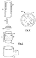
- the coupler 108 has an outer ring 114 and an inner ring 116 that are connected together by spokes 118.
- the illustrated embodiment shows four spokes 118, but any number of spokes 118 can connect the outer and inner rings 114, 116. In this embodiment, the spokes 118 extend radially between the outer and inner rings 114, 116.
- Figure 3 is a sectional view of the shaft 100 having the magnetoelastic element 104 and coupler 100 attached.
- the shaft 102 has one portion 120 with a large diameter and another portion 122 with a smaller diameter. The two different diameters allow the shaft 102 to accommodate the coupler 100.
- the smaller diameter portion 122 of the shaft 110 fits through the inner ring 116 of the coupler 100, while the larger diameter portion 120 fits through the element 104 itself.
- the coupler 100 should fit securely inside the element 104, such as via an interference fit. Ideally, the coupler 100 should not slip or move relative to the element 104; instead, the coupler 100 and the element 104 should move together as if they are a single piece.
- the coupler 100 is attached to the smaller diameter portion 122 of the shaft 102 and the magnetoelastic element 104 is attached to the larger diameter portion 120 of the shaft 102.
- the shaft 102, coupler 100 and element 104 may be connected to each other via welding, interference fit, or any other method.
- the coupler 100 may also be attached to the middle of the shaft 102 rather than at the shaft's end. Regardless of how or where the coupler 100 attaches the element 104 to the shaft 102, the coupler 100 attenuates the torque applied to the shaft 102 so that the forces ultimately reaching the element 104 are smaller than those experienced by the shaft 102. More particularly, the smaller diameter portion 122 of the shaft 102 is allowed to twist inside the element 104 without directly twisting the element 104 itself.
- the coupler 100 transfers some, but not all, of the twisting forces in the shaft 102 to the element 104.
- torsion forces in the smaller portion 122 of the shaft 102 are absorbed and are transferred to the element 104 in part through the radial spokes 108.
- FIG. 1 through 3 reduces the torsion forces that reach the torsion forces that reach the element 104 via radially extending spokes 118.
- Figures 4 and 5 illustrate a coupler 200 according to another embodiment of the invention.
- the coupler 200 in this embodiment attaches a pair of outer rings 202a, 202b and a pair of inner rings 204a, 204b together via axial spokes 206 rather than radial spokes.
- Tabs 208 extending from the outer rings 202a, 202b and the inner rings 204a, 204b provide anchoring points for the axial spokes 206 while still allowing the inner rings 204a, 204b to twist independently of the outer rings 202a, 202b.
- this structure can allow reduction of the diameter difference between the smaller diameter portion 122 and the larger diameter portion 120 of the shaft 102 and also reduces the length of the smaller diameter portion 122, preserving more of the original shaft dimensions.
- the outer rings 202a, 202b are attached to the magnetoelastic element 104 and the inner rings 204a, 204b are attached to the shaft 102.
- the coupler 200 in this embodiment allows the smaller diameter portion 122 of the shaft 102 to twist more freely inside the element 104, causing the coupler 200 to absorb some of the torsion forces in the shaft 102 while transferring the remaining torsion forces to the element 104. As a result, the torsion forces experienced by the element 104 are lower than the torsion forces in the shaft 102.
- the coupler 100 acts as a spring member that absorbs some of the torsion forces in the shaft 102 before transferring the remaining forces to the element 104.
- the coupler 100, 200 allows the element 104 to twist an amount proportional to the applied torque in the shaft 102.
- the coupler 100, 200 is made of a resilient material with predictable deformation characteristics so that the relationship between the applied torque in the shaft 102 and the torque actually experienced by the element 104 can be calculated easily. Those of ordinary skill in the art would be able to determine, without undue experimentation, the relationship between the torsion forces in the element and the corresponding torsion forces in the shaft 102.
- the dimensions of the spokes, the inner ring, and the outer ring can be varied to vary the relationship between the shaft torsion forces and the element torsion forces.
- the relationship can be, for example, determined empirically.
- the magnetometer in the torque sensor (not shown) detects the torsion force experienced by the element 104 and calculates the applied torque from the measured torsion force.
- the coupler By connecting the magnetoelastic element 104 to the shaft 102 via the coupler rather than directly onto the shaft 102, the element 104 is protected from torsion forces that would otherwise permanently change the element's magnetic characteristics. Further, the coupler avoids the need to thicken the walls of the element 104 to handle larger torsion forces, reducing the total amount of space occupied by the element 104. The coupler therefore expands the safe operating region of torque sensors and allows torque sensors to sense higher levels of applied torque in the shaft 102 without transferring those higher, and possibly damaging, higher torsion forces directly to the element 104 itself.
- couplers 100 with spoked structures covers any compliant coupler structure.
- the coupler 100 can be incorporated into any torque sensor where torque limitations within the sensor components are a concern, such as a strain gauge, etc., and is not limited to torque sensors using magnetometers.
Landscapes
- Physics & Mathematics (AREA)
- Electromagnetism (AREA)
- General Physics & Mathematics (AREA)
- Power Steering Mechanism (AREA)
- Force Measurement Appropriate To Specific Purposes (AREA)
Abstract
Description
- The present invention is directed to torque sensors, and more particularly to couplers for magnetoelastic torque sensors that measure torque in a shaft by monitoring changes in a magnetic field generated by a magnetoelastic element coupled to the shaft.
- Torque sensors known in the art rely on a magnetoelastic element attached to a component to sense torsion forces in the component. Deformation in the component caused by applied torque deforms the magnetoelastic element, resulting in a magnetic field that is proportional to the applied torque. A magnetometer disposed near the element detects the magnitude and polarity of the magnetic field, which indicates the magnitude and polarity of the applied torque.
- To ensure that the deformation in the magnetoelastic element accurately reflects the torque applied to the shaft, the magnetoelastic element is usually a cylinder tightly coupled to the shaft. Depending on the material and process used to manufacture the magnetoelastic element, however, the applied torque may be so great that it causes irreversible changes in the element, permanently deforming it. For example, elements having a magnetoelastic coating applied to a substrate may be axially compressed before the coating is applied to optimize stresses in the coating. The substrate is ideally kept relatively thin in these types of elements, but minimizing substrate thickness also compromises the substrate's ability to handle larger applied torques.
- If permanent deformation of the element occurs due to excessive applied torque, the sensor does not return to zero when the shaft is released from the applied torque. This change in the magnetoelastic element is called "zero-shift" because the zero point of the magnetic field generated by the element shifts due to the permanent deformation.
- Current applications often place shafts in environments that allow the shaft to twist more than the magnetoelastic element is capable of handling without permanent deformation.
- Accordingly, the present invention is directed to a coupler that acts as an interface between the magnetoelastic element and the shaft. A portion of the shaft is allowed to twist freely inside the element, and the coupler transfers a portion of the torsion forces in the shaft to the element. The element deforms and generates a magnetic field corresponding to the applied torque in the shaft, but the torque in the element is less than the applied torque in the shaft. The applied torque can then be determined based on a relationship between the torque in the shaft and the torque in the element. By reducing the torsion forces actually reaching the element, the element can be used to measure forces that would ordinarily cause permanent deformation in the element.
- In one embodiment, a portion of the shaft has a reduced diameter to accommodate the coupler. The coupler is formed with an inner ring that accommodates the reduced diameter portion and an outer ring that fits inside the magnetoelastic element. The shaft portion having the original shaft diameter is attached to the element itself.
-
- Figure 1 is an exploded view of a shaft and torque sensor incorporating a coupler according to one embodiment of the invention;
- Figure 2 is a plan view of the coupler according to one embodiment of the invention;
- Figure 3 is a side sectional view of the coupler in Figure 1 attached to a shaft and magnetoelastic element;
- Figure 4 is a perspective view of a coupler according to another embodiment of the invention; and
- Figure 5 is a side sectional view of the coupler in Figure 3 attached to a shaft and magnetoelastic element.
-
- Referring to Figures 1 through 3, the invention is directed a
coupler 100 that couples ashaft 102 with a torque element, such as amagnetoelastic element 104. Themagnetoelastic element 104 cooperates with a response detector, such as amagnetometer 106, to form atorque sensor 108. Themagnetometer 106 measures changes in a magnetic field generated by theelement 104 when it is deformed via torsion forces. Other torque elements and response detectors may be used to form the torque sensor as long as the torque element generates a torque response in response to an applied torque and the response detector is designed to detect the specific torque response generated by the torque element and generate a corresponding output. Theelement 104 may have any structure that allows it to deform in a predictable manner based on the applied torque on theshaft 102, such as a sleeve made of magnetic material or, as illustrated in the Figures, adeformable sleeve 110 with amagnetic coating 112 applied on it. - Rather than allowing the
entire element 104 to contact theshaft 102 directly, thecoupler 100 acts as an interface between theelement 104 and theshaft 102. Thecoupler 100 prevents theelement 104 from experiencing torsion forces that may cause permanent deformation and zero shift. In one embodiment, thecoupler 108 has anouter ring 114 and aninner ring 116 that are connected together byspokes 118. The illustrated embodiment shows fourspokes 118, but any number ofspokes 118 can connect the outer andinner rings spokes 118 extend radially between the outer andinner rings - Figure 3 is a sectional view of the
shaft 100 having themagnetoelastic element 104 andcoupler 100 attached. In the embodiment shown in Figures 1 through 3, theshaft 102 has oneportion 120 with a large diameter and anotherportion 122 with a smaller diameter. The two different diameters allow theshaft 102 to accommodate thecoupler 100. Thesmaller diameter portion 122 of theshaft 110 fits through theinner ring 116 of thecoupler 100, while thelarger diameter portion 120 fits through theelement 104 itself. Thecoupler 100 should fit securely inside theelement 104, such as via an interference fit. Ideally, thecoupler 100 should not slip or move relative to theelement 104; instead, thecoupler 100 and theelement 104 should move together as if they are a single piece. - The
coupler 100 is attached to thesmaller diameter portion 122 of theshaft 102 and themagnetoelastic element 104 is attached to thelarger diameter portion 120 of theshaft 102. Theshaft 102,coupler 100 andelement 104 may be connected to each other via welding, interference fit, or any other method. Thecoupler 100 may also be attached to the middle of theshaft 102 rather than at the shaft's end. Regardless of how or where thecoupler 100 attaches theelement 104 to theshaft 102, thecoupler 100 attenuates the torque applied to theshaft 102 so that the forces ultimately reaching theelement 104 are smaller than those experienced by theshaft 102. More particularly, thesmaller diameter portion 122 of theshaft 102 is allowed to twist inside theelement 104 without directly twisting theelement 104 itself. Thecoupler 100 transfers some, but not all, of the twisting forces in theshaft 102 to theelement 104. In the embodiment shown in Figures 1 through 3, torsion forces in thesmaller portion 122 of theshaft 102 are absorbed and are transferred to theelement 104 in part through theradial spokes 108. - The
coupler 100 shown in Figures 1 through 3 reduces the torsion forces that reach the torsion forces that reach theelement 104 via radially extendingspokes 118. Figures 4 and 5 illustrate acoupler 200 according to another embodiment of the invention. Thecoupler 200 in this embodiment attaches a pair ofouter rings inner rings axial spokes 206 rather than radial spokes.Tabs 208 extending from theouter rings inner rings axial spokes 206 while still allowing theinner rings outer rings smaller diameter portion 122 and thelarger diameter portion 120 of theshaft 102 and also reduces the length of thesmaller diameter portion 122, preserving more of the original shaft dimensions. - The
outer rings magnetoelastic element 104 and theinner rings shaft 102. As in the previous embodiment, thecoupler 200 in this embodiment allows thesmaller diameter portion 122 of theshaft 102 to twist more freely inside theelement 104, causing thecoupler 200 to absorb some of the torsion forces in theshaft 102 while transferring the remaining torsion forces to theelement 104. As a result, the torsion forces experienced by theelement 104 are lower than the torsion forces in theshaft 102. - Regardless of the spoke orientation, the
coupler 100 acts as a spring member that absorbs some of the torsion forces in theshaft 102 before transferring the remaining forces to theelement 104. In general, thecoupler element 104 to twist an amount proportional to the applied torque in theshaft 102. Preferably, thecoupler shaft 102 and the torque actually experienced by theelement 104 can be calculated easily. Those of ordinary skill in the art would be able to determine, without undue experimentation, the relationship between the torsion forces in the element and the corresponding torsion forces in theshaft 102. Further, the dimensions of the spokes, the inner ring, and the outer ring can be varied to vary the relationship between the shaft torsion forces and the element torsion forces. The relationship can be, for example, determined empirically. In one embodiment, the magnetometer in the torque sensor (not shown) detects the torsion force experienced by theelement 104 and calculates the applied torque from the measured torsion force. - By connecting the
magnetoelastic element 104 to theshaft 102 via the coupler rather than directly onto theshaft 102, theelement 104 is protected from torsion forces that would otherwise permanently change the element's magnetic characteristics. Further, the coupler avoids the need to thicken the walls of theelement 104 to handle larger torsion forces, reducing the total amount of space occupied by theelement 104. The coupler therefore expands the safe operating region of torque sensors and allows torque sensors to sense higher levels of applied torque in theshaft 102 without transferring those higher, and possibly damaging, higher torsion forces directly to theelement 104 itself. - Note that although the embodiments shown above illustrate
couplers 100 with spoked structures, the invention covers any compliant coupler structure. Further, thecoupler 100 can be incorporated into any torque sensor where torque limitations within the sensor components are a concern, such as a strain gauge, etc., and is not limited to torque sensors using magnetometers. - It should be understood that various alternatives to the embodiments of the invention described herein may be employed in practicing the invention. It is intended that the following claims define the scope of the invention and that the method and apparatus within the scope of these claims and their equivalents be covered thereby.
Claims (16)
- A torque sensor that senses a torsion force applied to a shaft, comprising:a torque element connected to at least a portion of the shaft, wherein the torque element generates a torque response in response to the torsion force;a response detector in communication with the torque element, wherein the an output responsive to the torque response; anda coupler attached to the shaft and the torque element, wherein the coupler transfers a portion of the torsion force applied to the shaft to the torque element.
- The torque sensor of claim 1, wherein the torque element is a magnetoelastic element that generates a magnetic field as the torque response when deformed by the torsion force and the response detector is a magnetometer encircling at least a portion of the magnetoelastic element to sense the magnetic field.
- The torque sensor of claim 1, wherein the coupler comprises:an inner ring coupled to the shaft;an outer ring coupled to the torque element; anda plurality of spokes connecting the inner ring and the outer ring.
- The torque sensor of claim 3, wherein the plurality of spokes extends radially between the inner ring and the outer ring.
- The torque sensor of claim 3, wherein the plurality of spokes extends axially between the inner ring and the outer ring.
- The torque sensor of claim 5, further comprising a second inner ring and a second outer ring.
- The torque sensor of claim 6, wherein the second inner ring is connected to the outer ring and the second outer ring is connected to the inner ring via said plurality of spokes.
- The torque sensor of claim 3, wherein the shaft has a larger diameter portion corresponding to an inner diameter of the magnetoelastic element and a smaller diameter portion corresponding to a diameter of the inner ring.
- The torque sensor of claim 1, wherein the coupler is made of a resilient material.
- A coupler for transferring a torsion force applied to a shaft to a torque element in a torque sensor, comprising:a first surface connected to the shaft;a second surface connected to the ring; anda compliant portion connected to the first and second surfaces, wherein at least one of the first surface, second surface, and compliant portion transfers a portion of the torsion force applied to the shaft to the torque element.
- The coupler of claim 10, wherein the first surface is an inner ring, the second surface is an outer ring, and the compliant portion is a plurality of spokes connecting the inner ring and the outer ring.
- The coupler of claim 11, wherein the plurality of spokes extends radially between the inner ring and the outer ring.
- The coupler of claim 11, wherein the plurality of spokes extends axially between the inner ring and the outer ring.
- The coupler of claim 13, further comprising a second inner ring and a second outer ring, wherein the second inner ring is connected to the outer ring and the second outer ring is connected to the inner ring via said plurality of spokes.
- A torque sensor that senses a torsion force applied to a shaft, comprising:a magnetoelastic element encircling at least a portion of the shaft, wherein the magnetoelastic element generates a magnetic field when deformed by the torsion force;a magnetometer encircling at least a portion of the magnetoelastic element, wherein the magnetometer senses the magnetic field and generates an output responsive to the magnetic field; anda coupler attached to the shaft and the magnetoelastic element, wherein the coupler transfers a portion of the torsion force applied to the shaft to the magnetoelastic element, and wherein the coupler comprisesfirst and second inner rings,first and second outer rings, anda plurality of axially-extending spokes connecting the first inner ring to the second outer ring and connecting the first outer ring to the second inner ring.
- The torque sensor of claim 15, wherein the shaft has a larger diameter portion corresponding to an inner diameter of the magnetoelastic element and a smaller diameter portion corresponding to a diameter of the inner ring.
Applications Claiming Priority (2)
| Application Number | Priority Date | Filing Date | Title |
|---|---|---|---|
| US10/238,673 US6948384B2 (en) | 2002-09-10 | 2002-09-10 | Coupler for torque sensor |
| US238673 | 2002-09-10 |
Publications (3)
| Publication Number | Publication Date |
|---|---|
| EP1398607A2 true EP1398607A2 (en) | 2004-03-17 |
| EP1398607A3 EP1398607A3 (en) | 2004-06-23 |
| EP1398607B1 EP1398607B1 (en) | 2014-05-07 |
Family
ID=31887739
Family Applications (1)
| Application Number | Title | Priority Date | Filing Date |
|---|---|---|---|
| EP03077050.7A Expired - Lifetime EP1398607B1 (en) | 2002-09-10 | 2003-07-01 | Coupler for torque sensor |
Country Status (2)
| Country | Link |
|---|---|
| US (1) | US6948384B2 (en) |
| EP (1) | EP1398607B1 (en) |
Cited By (6)
| Publication number | Priority date | Publication date | Assignee | Title |
|---|---|---|---|---|
| EP1978343A3 (en) * | 2007-04-03 | 2009-11-04 | Shimano Inc. | Torsion-detecting sleeve member and torque-detecting device |
| DE102013018700A1 (en) | 2013-11-08 | 2015-05-13 | Schaeffler Technologies Gmbh & Co. Kg | Built-in element for receiving measuring instruments |
| DE102014205973A1 (en) | 2014-03-31 | 2015-10-01 | Schaeffler Technologies AG & Co. KG | Built-in element with a measuring device |
| DE102020117007A1 (en) | 2020-06-29 | 2021-12-30 | Schaeffler Technologies AG & Co. KG | Arrangement for detecting a torque on a machine element and vehicle with such an arrangement |
| DE102020120672A1 (en) | 2020-08-05 | 2022-02-10 | Schaeffler Technologies AG & Co. KG | Magnetoelastic torque sensor with a magnetized sleeve as the primary sensor |
| DE102020122116A1 (en) | 2020-08-25 | 2022-03-03 | Schaeffler Technologies AG & Co. KG | Torque sensor based on inverse magnetostriction |
Families Citing this family (4)
| Publication number | Priority date | Publication date | Assignee | Title |
|---|---|---|---|---|
| US7943421B2 (en) * | 2008-12-05 | 2011-05-17 | Taiwan Semiconductor Manufacturing Company, Ltd. | Component stacking using pre-formed adhesive films |
| JP5899090B2 (en) * | 2012-09-14 | 2016-04-06 | 日立オートモティブシステムズステアリング株式会社 | Torque sensor |
| FR3133080B1 (en) * | 2022-02-25 | 2024-05-31 | Ntn Snr Roulements | Method for producing an encoder |
| CN118294050B (en) * | 2024-04-25 | 2024-09-17 | 昆山朗德森机电科技有限公司 | High-precision torque sensor |
Citations (2)
| Publication number | Priority date | Publication date | Assignee | Title |
|---|---|---|---|---|
| DE3437379A1 (en) | 1983-10-12 | 1985-04-25 | Bently Nevada Corp., Minden, Nev. | Device for measuring the rotary or bending force exerted on a shaft |
| EP0442091A1 (en) | 1990-02-15 | 1991-08-21 | Robert Bosch Gmbh | Device for measuring the torque of a rotating or stationary machine part |
Family Cites Families (8)
| Publication number | Priority date | Publication date | Assignee | Title |
|---|---|---|---|---|
| US3729991A (en) * | 1971-05-17 | 1973-05-01 | Spearhead Inc | Capacitive displacement transducer |
| US4899598A (en) * | 1988-08-04 | 1990-02-13 | Caterpillar Inc. | Apparatus for measuring torque applied to a shaft |
| JP2884768B2 (en) * | 1989-12-08 | 1999-04-19 | 株式会社デンソー | Steering torque detector |
| FR2774349B1 (en) * | 1998-02-04 | 2000-03-03 | Roulements Soc Nouvelle | STEERING COLUMN WITH COUPLEMETER |
| FR2774348B1 (en) * | 1998-02-04 | 2000-03-03 | Roulements Soc Nouvelle | STEERING WHEEL ARM WITH INTEGRATED OR RELATED TORQUE SENSOR FOR VEHICLE STEERING DEVICE |
| US6418797B1 (en) * | 1998-03-04 | 2002-07-16 | Graber Products, Inc. | Apparatus and method for sensing power in a bicycle |
| SE517238C2 (en) * | 2000-09-27 | 2002-05-14 | Abb Ab | Torque encoder and use of a torque encoder |
| JP2004020527A (en) * | 2002-06-20 | 2004-01-22 | Nippon Soken Inc | Torque sensor |
-
2002
- 2002-09-10 US US10/238,673 patent/US6948384B2/en not_active Expired - Fee Related
-
2003
- 2003-07-01 EP EP03077050.7A patent/EP1398607B1/en not_active Expired - Lifetime
Patent Citations (2)
| Publication number | Priority date | Publication date | Assignee | Title |
|---|---|---|---|---|
| DE3437379A1 (en) | 1983-10-12 | 1985-04-25 | Bently Nevada Corp., Minden, Nev. | Device for measuring the rotary or bending force exerted on a shaft |
| EP0442091A1 (en) | 1990-02-15 | 1991-08-21 | Robert Bosch Gmbh | Device for measuring the torque of a rotating or stationary machine part |
Cited By (10)
| Publication number | Priority date | Publication date | Assignee | Title |
|---|---|---|---|---|
| EP1978343A3 (en) * | 2007-04-03 | 2009-11-04 | Shimano Inc. | Torsion-detecting sleeve member and torque-detecting device |
| CN101281070B (en) * | 2007-04-03 | 2012-06-20 | 株式会社岛野 | Torsion-detecting sleeve member and torque-detecting device using the same |
| DE102013018700A1 (en) | 2013-11-08 | 2015-05-13 | Schaeffler Technologies Gmbh & Co. Kg | Built-in element for receiving measuring instruments |
| WO2015067249A1 (en) | 2013-11-08 | 2015-05-14 | Schaeffler Technologies AG & Co. KG | Integration element for seating measuring equipment |
| US10041820B2 (en) | 2013-11-08 | 2018-08-07 | Schaeffler Technologies AG & Co. KG | Integration element for seating measuring equipment |
| DE102013018700B4 (en) * | 2013-11-08 | 2020-10-08 | Schaeffler Technologies AG & Co. KG | Installation element to accommodate measuring equipment |
| DE102014205973A1 (en) | 2014-03-31 | 2015-10-01 | Schaeffler Technologies AG & Co. KG | Built-in element with a measuring device |
| DE102020117007A1 (en) | 2020-06-29 | 2021-12-30 | Schaeffler Technologies AG & Co. KG | Arrangement for detecting a torque on a machine element and vehicle with such an arrangement |
| DE102020120672A1 (en) | 2020-08-05 | 2022-02-10 | Schaeffler Technologies AG & Co. KG | Magnetoelastic torque sensor with a magnetized sleeve as the primary sensor |
| DE102020122116A1 (en) | 2020-08-25 | 2022-03-03 | Schaeffler Technologies AG & Co. KG | Torque sensor based on inverse magnetostriction |
Also Published As
| Publication number | Publication date |
|---|---|
| EP1398607B1 (en) | 2014-05-07 |
| US6948384B2 (en) | 2005-09-27 |
| EP1398607A3 (en) | 2004-06-23 |
| US20040045374A1 (en) | 2004-03-11 |
Similar Documents
| Publication | Publication Date | Title |
|---|---|---|
| US6948384B2 (en) | Coupler for torque sensor | |
| US20080170817A1 (en) | Bearing Assemly With Integrated Sensor System | |
| EP2828043B1 (en) | High density actuator having a harmonic drive and a torque limiting assembly | |
| US7707893B2 (en) | Industrial robot | |
| CN102119324B (en) | Torque measuring device with redundant torque transmission paths and fail-safe mechanism | |
| US11248972B2 (en) | Torque sensor for a rotating element using a mechanical friction coupling | |
| JP2014512977A (en) | Power wrench with torque detection unit | |
| JP2018503828A (en) | Sensor device for indirectly detecting torque of shaft rotatably supported | |
| US9353797B2 (en) | Bearing ring for a bearing, in particular for a rolling or sliding bearing | |
| JP5411614B2 (en) | Tire acting force detection device | |
| EP1037029A3 (en) | Torque sensing apparatus | |
| EP2436936B1 (en) | Bolt preloading check system | |
| JP2007230507A (en) | Suspension system of vehicle, and ball stud used for suspension system | |
| KR100813681B1 (en) | Force sensor | |
| EP4232786B1 (en) | Multi-axis force-torque sensing device and holding structure for use therewith | |
| JP5495397B2 (en) | Force measuring ring with annular housing | |
| EP3296707B1 (en) | Retaining systems and methods | |
| JP2564055B2 (en) | Magnetostrictive torque sensor overload prevention device | |
| CN212228277U (en) | Novel diamond-shaped torque overload prevention sensor | |
| EP2438318B1 (en) | Load-measuring bearing unit | |
| JPS6130187Y2 (en) | ||
| JP7021835B2 (en) | Torque sensor | |
| JPS5852538A (en) | Torque detector | |
| WO2009076988A1 (en) | Bearing and sensor unit | |
| GB2238623A (en) | Torque measuring apparatus |
Legal Events
| Date | Code | Title | Description |
|---|---|---|---|
| PUAI | Public reference made under article 153(3) epc to a published international application that has entered the european phase |
Free format text: ORIGINAL CODE: 0009012 |
|
| AK | Designated contracting states |
Kind code of ref document: A2 Designated state(s): AT BE BG CH CY CZ DE DK EE ES FI FR GB GR HU IE IT LI LU MC NL PT RO SE SI SK TR |
|
| AX | Request for extension of the european patent |
Extension state: AL LT LV MK |
|
| PUAL | Search report despatched |
Free format text: ORIGINAL CODE: 0009013 |
|
| AK | Designated contracting states |
Kind code of ref document: A3 Designated state(s): AT BE BG CH CY CZ DE DK EE ES FI FR GB GR HU IE IT LI LU MC NL PT RO SE SI SK TR |
|
| AX | Request for extension of the european patent |
Extension state: AL LT LV MK |
|
| 17P | Request for examination filed |
Effective date: 20041102 |
|
| AKX | Designation fees paid |
Designated state(s): DE FR GB SE |
|
| 17Q | First examination report despatched |
Effective date: 20050217 |
|
| RAP1 | Party data changed (applicant data changed or rights of an application transferred) |
Owner name: CONTINENTAL AUTOMOTIVE SYSTEMS US, INC. |
|
| GRAP | Despatch of communication of intention to grant a patent |
Free format text: ORIGINAL CODE: EPIDOSNIGR1 |
|
| INTG | Intention to grant announced |
Effective date: 20131205 |
|
| GRAS | Grant fee paid |
Free format text: ORIGINAL CODE: EPIDOSNIGR3 |
|
| GRAA | (expected) grant |
Free format text: ORIGINAL CODE: 0009210 |
|
| RAP1 | Party data changed (applicant data changed or rights of an application transferred) |
Owner name: CONTINENTAL AUTOMOTIVE SYSTEMS, INC. |
|
| AK | Designated contracting states |
Kind code of ref document: B1 Designated state(s): DE FR GB SE |
|
| REG | Reference to a national code |
Ref country code: GB Ref legal event code: FG4D |
|
| REG | Reference to a national code |
Ref country code: DE Ref legal event code: R096 Ref document number: 60346118 Country of ref document: DE Effective date: 20140618 |
|
| PG25 | Lapsed in a contracting state [announced via postgrant information from national office to epo] |
Ref country code: SE Free format text: LAPSE BECAUSE OF FAILURE TO SUBMIT A TRANSLATION OF THE DESCRIPTION OR TO PAY THE FEE WITHIN THE PRESCRIBED TIME-LIMIT Effective date: 20140507 |
|
| REG | Reference to a national code |
Ref country code: DE Ref legal event code: R097 Ref document number: 60346118 Country of ref document: DE |
|
| PLBE | No opposition filed within time limit |
Free format text: ORIGINAL CODE: 0009261 |
|
| STAA | Information on the status of an ep patent application or granted ep patent |
Free format text: STATUS: NO OPPOSITION FILED WITHIN TIME LIMIT |
|
| 26N | No opposition filed |
Effective date: 20150210 |
|
| REG | Reference to a national code |
Ref country code: FR Ref legal event code: ST Effective date: 20150331 |
|
| GBPC | Gb: european patent ceased through non-payment of renewal fee |
Effective date: 20140807 |
|
| REG | Reference to a national code |
Ref country code: DE Ref legal event code: R097 Ref document number: 60346118 Country of ref document: DE Effective date: 20150210 |
|
| PG25 | Lapsed in a contracting state [announced via postgrant information from national office to epo] |
Ref country code: FR Free format text: LAPSE BECAUSE OF NON-PAYMENT OF DUE FEES Effective date: 20140731 |
|
| PG25 | Lapsed in a contracting state [announced via postgrant information from national office to epo] |
Ref country code: GB Free format text: LAPSE BECAUSE OF NON-PAYMENT OF DUE FEES Effective date: 20140807 |
|
| PGFP | Annual fee paid to national office [announced via postgrant information from national office to epo] |
Ref country code: DE Payment date: 20160731 Year of fee payment: 14 |
|
| REG | Reference to a national code |
Ref country code: DE Ref legal event code: R119 Ref document number: 60346118 Country of ref document: DE |
|
| PG25 | Lapsed in a contracting state [announced via postgrant information from national office to epo] |
Ref country code: DE Free format text: LAPSE BECAUSE OF NON-PAYMENT OF DUE FEES Effective date: 20180201 |