EP1398557A1 - Manufacturing process for a device for connection tubes or pipes to a pipe end and connection so obtained - Google Patents
Manufacturing process for a device for connection tubes or pipes to a pipe end and connection so obtained Download PDFInfo
- Publication number
- EP1398557A1 EP1398557A1 EP03292253A EP03292253A EP1398557A1 EP 1398557 A1 EP1398557 A1 EP 1398557A1 EP 03292253 A EP03292253 A EP 03292253A EP 03292253 A EP03292253 A EP 03292253A EP 1398557 A1 EP1398557 A1 EP 1398557A1
- Authority
- EP
- European Patent Office
- Prior art keywords
- pipe
- tube
- annular
- nozzle
- annular relief
- Prior art date
- Legal status (The legal status is an assumption and is not a legal conclusion. Google has not performed a legal analysis and makes no representation as to the accuracy of the status listed.)
- Granted
Links
Images

Classifications
-
- B—PERFORMING OPERATIONS; TRANSPORTING
- B29—WORKING OF PLASTICS; WORKING OF SUBSTANCES IN A PLASTIC STATE IN GENERAL
- B29C—SHAPING OR JOINING OF PLASTICS; SHAPING OF MATERIAL IN A PLASTIC STATE, NOT OTHERWISE PROVIDED FOR; AFTER-TREATMENT OF THE SHAPED PRODUCTS, e.g. REPAIRING
- B29C45/00—Injection moulding, i.e. forcing the required volume of moulding material through a nozzle into a closed mould; Apparatus therefor
- B29C45/14—Injection moulding, i.e. forcing the required volume of moulding material through a nozzle into a closed mould; Apparatus therefor incorporating preformed parts or layers, e.g. injection moulding around inserts or for coating articles
- B29C45/14598—Coating tubular articles
- B29C45/14614—Joining tubular articles
-
- B—PERFORMING OPERATIONS; TRANSPORTING
- B29—WORKING OF PLASTICS; WORKING OF SUBSTANCES IN A PLASTIC STATE IN GENERAL
- B29C—SHAPING OR JOINING OF PLASTICS; SHAPING OF MATERIAL IN A PLASTIC STATE, NOT OTHERWISE PROVIDED FOR; AFTER-TREATMENT OF THE SHAPED PRODUCTS, e.g. REPAIRING
- B29C45/00—Injection moulding, i.e. forcing the required volume of moulding material through a nozzle into a closed mould; Apparatus therefor
- B29C45/14—Injection moulding, i.e. forcing the required volume of moulding material through a nozzle into a closed mould; Apparatus therefor incorporating preformed parts or layers, e.g. injection moulding around inserts or for coating articles
- B29C45/1418—Injection moulding, i.e. forcing the required volume of moulding material through a nozzle into a closed mould; Apparatus therefor incorporating preformed parts or layers, e.g. injection moulding around inserts or for coating articles the inserts being deformed or preformed, e.g. by the injection pressure
- B29C45/14221—Injection moulding, i.e. forcing the required volume of moulding material through a nozzle into a closed mould; Apparatus therefor incorporating preformed parts or layers, e.g. injection moulding around inserts or for coating articles the inserts being deformed or preformed, e.g. by the injection pressure by tools, e.g. cutting means
-
- F—MECHANICAL ENGINEERING; LIGHTING; HEATING; WEAPONS; BLASTING
- F16—ENGINEERING ELEMENTS AND UNITS; GENERAL MEASURES FOR PRODUCING AND MAINTAINING EFFECTIVE FUNCTIONING OF MACHINES OR INSTALLATIONS; THERMAL INSULATION IN GENERAL
- F16L—PIPES; JOINTS OR FITTINGS FOR PIPES; SUPPORTS FOR PIPES, CABLES OR PROTECTIVE TUBING; MEANS FOR THERMAL INSULATION IN GENERAL
- F16L33/00—Arrangements for connecting hoses to rigid members; Rigid hose connectors, i.e. single members engaging both hoses
- F16L33/24—Arrangements for connecting hoses to rigid members; Rigid hose connectors, i.e. single members engaging both hoses with parts screwed directly on or into the hose
- F16L33/245—Arrangements for connecting hoses to rigid members; Rigid hose connectors, i.e. single members engaging both hoses with parts screwed directly on or into the hose the inner or outer part being moulded in situ
Definitions
- the invention relates to a device for connecting tubes or pipes to a mouthpiece and its method of production.
- Tube connection devices or pipes on a nozzle are generally used for pipe assembly conveying all kinds of fluids for internal combustion engine of vehicles automobiles or for any other application requiring a tube connection or pipes. It is therefore particularly important to prevent any risk of leakage during of this connection.
- WO-A-0077440 discloses a method of connecting tubes or pipes (a) on a tip (b) in which it is proposed to perform the molding of a material plastic (c) at least to the right of the zones in which the pipes cooperate with the tip.
- the molded plastics material (c) serves to secure the hose (a) on the nozzle (b) when withdrawing by applying a force of compression on the pipe (a).
- This plastic material (c) is in contact with both with the tip (b) and with the pipe (a) as shown in figure 1.
- patent FR-A-2,755,494 proposes, to cause deformation in the less elastic of an annular portion of the pipe, to force it to penetrate in at least one annular recess of the nozzle, to be applied under pressure fluid and solidifiable material around the pipe portion. So that's the matter injection which causes the deformation of the pipe as confirmed by the figures of the document in which FIG. 1 shows that, in the closed position of the mold, before injection, the pipe is not deformed.
- This solution is a complex solution to implement because sensitive to a large number of parameters (temperature, strength of materials) and requires on the one hand injection pressures on the other hand, large amounts of injection materials. In all This solution is characterized by the fact that the pipe is deformed during the injection of material and not before the injection of material so that the deformation is difficult to master.
- US Pat. No. 5,411,300 describes a solution in which the improvement of the waterproofing relies on two parameters, namely on the one hand the elasticity of the pipe coming to cover the tip, on the other hand, the coefficient removing the lid or overmolded ring.
- the pipe is chosen for allow an increase in its diameter of 20 to 30% during its fitting on the endpiece, which has the consequence of ensuring then a good sealing between tip and hose. Conversely, it is sometimes difficult to put such a hose on the tip.
- the withdrawal of the coin overmoulded chosen to prevent the appearance of tension cracks, promotes bringing the contact pressure of the pipe, the ring and the nozzle into contact pressure. In Consequently, the seal is essentially obtained by removing the material molded.
- the fact that the pipe may not penetrate the hollows between two annular reliefs of the tip is not addressed or appears as a priori settled by the elasticity of the pipe.
- the mold is thus realized in a such as the mold parts, represented at 50, for generating a deformation of the pipe, are distant from each other, in any case, from a distance greater than that separating two annular reliefs of the tip (see Figures 5, 10 and 11). These mold parts are therefore unable to allow the elimination of empty spaces made in the vicinity of the annular reliefs of the mouthpiece.
- An object of the present invention is therefore to propose a method and a device connections whose designs make it possible to eliminate the risks of leakage of fluids circulating in the pipes, especially when this fluid is under pressure, improving the seal being obtained by increasing the contact pressure between pipe and tip using mechanical means, without have to know the characteristics of the material injection process overmoulded or injected material.
- Another object of the present invention is to propose a method and a device connection which designs can fill at least partially the free spaces observed between inner surface of the pipe and surface outer end of the tip when the tip has annular reliefs and to reinforce the pressure of contact between tip and pipe at the top of these reliefs in order to form perfectly secure sealing barriers.
- the subject of the invention is a method of manufacturing a device for connecting tubes or pipes to a nozzle, the nozzle comprising at least one, preferably a plurality of, annular reliefs arranged at intervals along the outer surface of the nozzle and defining between them hollow, the tube or elastically deformable hose being fitted on the mouthpiece and delimiting, at the vicinity of at least one of the flanks of the annular relief of the mouthpiece, a space between the internal surface of the tube and the bottom of the hollow or the outer surface of the tip, said method comprising at least one step of introducing the tip on which at least one hose is fitted into the mold cavity of a mold such that at least one annular relief of the tip covered by a pipe extends inside said molding cavity, a step of deformation of the tube or pipe by means of support pieces of the suitable mold to exert support forces on the tube or pipe and a step of introduction of plastic material in the mold cavity formed between the support members of the mold and the right of the annular relief of the tip to form by overmold
- the mold consists of two half-shells respectively comprising at least one pair of projections to constitute the support pieces when the mold is closed, said protrusions extending, in the closed position of the mold, on either side of the annular relief and, preferably, in the vicinity of adjacent secondary annular reliefs, these projections defining between them, at the right of the annular relief, a molding cavity ring in which is introduced the plastic material overmoulding.
- the mold can have as many pieces as needed depending on the number of lanes of the mouthpiece.
- the projections exert two bearing forces causing on the one hand a stretching of the tube or pipe on either side of the point support of the upper end and secondly a compression of said tube or pipe against the tip.
- the pipe is kept in compression against the tip in areas that have been squeezed during molding in order to reinforce the tightness of the whole.
- the subject of the invention is also a device for connecting tubes or pipes on a tip, the tip comprising at least one, preferably a plurality of, annular reliefs disposed at intervals along the outer surface of the mouthpiece and defining between them hollows, the elastically deformable tube or pipe being fitted on the mouthpiece and delimiting, in the vicinity of at least one of the flanks of each annular relief of the tip, a free space between inner surface of the tube and bottom of the hollow, a retaining piece such as a ring being overmolded on the annular relief of the tube or pipe to the right of said annular relief called annular relief main feature, characterized in that the retainer holds, resting on the tip, the tube or pipe stretched on both sides of the main annular relief.
- the ring is only molded to the right of the annular relief of the mouthpiece so that it is in contact only with the tube or pipe and no longer also with the tip as was previously the case.
- the withdrawal of the overmolded ring is homogeneous on its together and thus promotes the tightening of the tube or pipe on the tip.
- the tube or pipe is stretched on either side of the annular relief the tip so as to bear against the tip, on either side of said relief, before overmolding the ring and thus at least partially fill the free spaces formed near the flanks of the main annular relief between the inner surface of the tube and the outer surface, also called the hollow of the mouthpiece.
- Using the mold support forces to fill at least partially these spaces can guarantee this filling.
- the values of withholding of a device of connection according to the invention are higher than for the devices overmolding according to the state of the art.
- the overmolded ring can easily follow the possible movements of the pipe. What could not be the case of an overmolding of the state of the technical related to the tip.
- the absence of connection between ring and tip allows a reduction of the stresses undergone by the ring during a displacement relative between pipe and ring. At the same time, however, the stretching mechanically limit relative movements between pipe and tip.
- secondary annular reliefs are provided on the mouthpiece of on either side of the annular relief, which is the main one, to the right of which is overmolded Ring.
- These secondary annular reliefs respectively have a height lower than the main annular relief.
- These secondary annular reliefs preferably of the same height, define between them a bearing surface of the tube or pipe in the state fitted on the tip.
- the space to be filled will be every time formed in the interval between main annular relief and secondary annular relief.
- Optimum support of the mold will be positioned each time, in this interval, of preferably in the vicinity of the secondary annular relief, when the space to be filled extends the entire length of the gap to form a sealing barrier additional.
- the retainer holds the tube or pipe stretched on either side of the main annular relief, the tube or pipe being also held in abutment against the tip between the annular reliefs secondary and the main annular relief.
- the main annular relief to the right of which is overmolded the ring, is made in the form of a fir-type rib and is equidistant from each secondary annular relief.
- the two annular reliefs may consist of a fir-type vein or respectively by a fir-type rib and an olive, the olive exerting a retainer function of the hose on the nozzle.
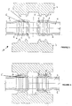
- connection device according to the invention shown in FIG. a three-way nozzle 1 on which are fitted pipes 2, a ring 3 being overmoulded on each pipe 2.
- the tip 1 has on each of its tracks a main annular relief 4 on which overlaps the pipe 2 fitted on the endpiece 1 and on the right which ring 3 is overmolded.
- Secondary annular reliefs 5, 6 are formed on the tip 1 on the part and other main annular relief 4.
- These secondary annular reliefs 5, 6 are preferably of the same height, less than that of the main annular relief 4, defining between them a surface support of the pipe 2 in the state fitted on the tip 1.
- the main annular relief 4 is made in the form of a rib fir type and is equidistant from each secondary annular relief 5, 6.
- One of the secondary annular reliefs consists of a fir-type vein 5 and the other of an olive 6, preventing tearing.
- the fir-type rib 5 of the secondary annular relief is such known in the state of the art, that is to say its slope favoring the fitting of the pipe 2 on the tip 1 while the fir-type rib constituting the main annular relief 4 is of the inverted type, that is to say that the rib of general conical shape flares towards the end of engagement of the pipe 2 on the tip 1, to further improve the seal.
- a tip 1 two lanes on which are fitted two pipes 2 covering respective main annular reliefs 4, is introduced into a mold M constituted two half-shells 7 which in the closed position of the mold M enclose the tip 1 and the two pipes 2 at the level of this main annular relief 4.
- the elastically deformable tube or pipe 2 is fitted on the end piece 1 and delimits, in the vicinity of at least one of the flanks of the main annular relief 4 of the tip 1, a free space E between inner surface of the tube and bottom of the hollow of the tip 1.
- This hollow corresponds to the outer surface of the tip extending between a main annular relief 4 and an annular relief secondary 5, 6 when this secondary annular relief 5, 6 is present or corresponds to the external surface of the tip 1 adjacent to the main annular relief 4 from which this relief originates.
- mold support parts 8 capable of exerting F support forces on the tube or pipe 2.
- This mold is in the form of two half-shells 7 which each comprise at least one pair of projections 8 which, in the closed position of the mold (FIG. 4), respectively exert a force F of support on the pipe 2 on either side of the main annular relief 4 and between it and a secondary annular relief 5 or 6.
- These supports 8 are made of such that at least one is disposed to the right of free space E between inner surface of the tube 2 and hollow of the tip.
- the ring 3 is made of polyamide 6.6, loaded or not.
Abstract
Description
L'invention concerne un dispositif de raccordement de tubes ou tuyaux sur un embout et son procédé de réalisation. Les dispositifs de raccordement de tubes ou tuyaux sur un embout sont généralement utilisés pour l'assemblage de tuyaux véhiculant toutes sortes de fluides pour moteur à combustion interne de véhicules automobiles ou pour toute autre application nécessitant une liaison de tubes ou tuyaux. Il est donc particulièrement important de prévenir tout risque de fuite lors de ce raccordement.The invention relates to a device for connecting tubes or pipes to a mouthpiece and its method of production. Tube connection devices or pipes on a nozzle are generally used for pipe assembly conveying all kinds of fluids for internal combustion engine of vehicles automobiles or for any other application requiring a tube connection or pipes. It is therefore particularly important to prevent any risk of leakage during of this connection.
On connaít par WO-A-0077440, un procédé de raccordement de tubes ou tuyaux (a) sur un embout (b) dans lequel on propose de réaliser le moulage d'une matière plastique (c) au moins au droit des zones dans lesquelles les tuyaux coopèrent avec l'embout. Lors du moulage, la matière plastique moulée (c) sert à fixer le tuyau (a) sur l'embout (b) lors de son retrait en appliquant un effort de compression sur le tuyau (a). Cette matière plastique (c) est en contact à la fois avec l'embout (b) et avec le tuyau (a) comme cela est visible dans la figure 1.WO-A-0077440 discloses a method of connecting tubes or pipes (a) on a tip (b) in which it is proposed to perform the molding of a material plastic (c) at least to the right of the zones in which the pipes cooperate with the tip. During molding, the molded plastics material (c) serves to secure the hose (a) on the nozzle (b) when withdrawing by applying a force of compression on the pipe (a). This plastic material (c) is in contact with both with the tip (b) and with the pipe (a) as shown in figure 1.
Il en résulte que, lors de variation de température, de pression et du fait que les matériaux du tuyau a et de l'embout b sont différents, les matériaux se déforment de manière différente d'un matériau à un autre, ce qui entraíne un risque de création de fuites.As a result, when there is a variation in temperature, pressure and the fact that materials of the pipe a and the tip b are different, the materials are deformed differently from one material to another, which leads to a risk of creating leaks.
De plus, le surmoulage de l'embout augmente inutilement le temps de cycle d'injection et la quantité de matière plastique injectéeIn addition, overmoulding the tip unnecessarily increases the cycle time of injection and the amount of plastic injected
Par ailleurs, plusieurs documents de l'état de la technique ont montré que pour obtenir une liaison parfaitement étanche entre un embout muni de relief(s) annulaire(s) et un tuyau élastiquement déformable emmanché sur l'embout, il fallait déformer le tuyau pour amener certaines de ses parties au contact de l'embout.Moreover, several documents of the state of the art have shown that for to obtain a perfectly tight connection between a tip provided with relief (s) annular (s) and an elastically deformable hose fitted on the endpiece, it had to deform the pipe to bring some of its parts into contact with the mouthpiece.
Ainsi, le brevet FR-A-2.755.494 propose, pour provoquer une déformation au moins élastique d'une portion annulaire du tuyau, pour le contraindre à pénétrer dans au moins un creux annulaire de l'embout, à appliquer sous pression une matière fluide et solidifiable autour de la portion de tuyau. C'est donc la matière d'injection qui provoque la déformation du tuyau comme le confirment les figures du document où la figure 1 montre, qu'en position fermée du moule, avant injection, le tuyau n'est pas déformé. Cette solution est une solution complexe à mettre en oeuvre car sensible à un grand nombre de paramètres (température, résistance des matériaux) et nécessite d'une part des pressions d'injection élevées, d'autre part, des quantités de matières d'injection importantes. En tout état de cause, cette solution se caractérise par le fait que le tuyau est déformé pendant l'injection de matière et non avant l'injection de matière de telle sorte que la déformation est difficilement maítrisable.Thus, patent FR-A-2,755,494 proposes, to cause deformation in the less elastic of an annular portion of the pipe, to force it to penetrate in at least one annular recess of the nozzle, to be applied under pressure fluid and solidifiable material around the pipe portion. So that's the matter injection which causes the deformation of the pipe as confirmed by the figures of the document in which FIG. 1 shows that, in the closed position of the mold, before injection, the pipe is not deformed. This solution is a complex solution to implement because sensitive to a large number of parameters (temperature, strength of materials) and requires on the one hand injection pressures on the other hand, large amounts of injection materials. In all This solution is characterized by the fact that the pipe is deformed during the injection of material and not before the injection of material so that the deformation is difficult to master.
Le brevet US-A-5.411.300 décrit quant à lui une solution dans laquelle l'amélioration de l'étanchéité repose sur deux paramètres, à savoir d'une part l'élasticité du tuyau venant à recouvrement de l'embout, d'autre part, le coefficient de retrait du couvercle ou bague surmoulée. En effet, le tuyau est choisi pour permettre une augmentation de son diamètre de 20 à 30 % lors de son emmanchement sur l'embout, ce qui a pour conséquence d'assurer ensuite une bonne étanchéité entre embout et tuyau. A l'inverse, il est parfois difficile d'emmancher un tel tuyau sur l'embout. Parallèlement, le retrait de la pièce surmoulée, choisi pour empêcher l'apparition de criques de tension, favorise l'amenée en pression de contact du tuyau, de la bague et de l'embout. En conséquence, l'étanchéité est essentiellement obtenue par le retrait de la matière surmoulée. Le fait que le tuyau puisse ne pas pénétrer dans les creux entre deux reliefs annulaires de l'embout n'est pas abordé ou apparaít comme a priori réglé par l'élasticité du tuyau. US Pat. No. 5,411,300 describes a solution in which the improvement of the waterproofing relies on two parameters, namely on the one hand the elasticity of the pipe coming to cover the tip, on the other hand, the coefficient removing the lid or overmolded ring. Indeed, the pipe is chosen for allow an increase in its diameter of 20 to 30% during its fitting on the endpiece, which has the consequence of ensuring then a good sealing between tip and hose. Conversely, it is sometimes difficult to put such a hose on the tip. At the same time, the withdrawal of the coin overmoulded, chosen to prevent the appearance of tension cracks, promotes bringing the contact pressure of the pipe, the ring and the nozzle into contact pressure. In Consequently, the seal is essentially obtained by removing the material molded. The fact that the pipe may not penetrate the hollows between two annular reliefs of the tip is not addressed or appears as a priori settled by the elasticity of the pipe.
Dans un mode de réalisation particulier, on décrit toutefois une solution dans laquelle on comprime des portions de tuyau avant injection de matière puis on assure un blocage axial de la bague surmoulée grâce au fait que la matière comprimée par des anneaux d'étanchéité faisant partie du moule s'expanse et forme des renflements de part et d'autre de la bague comme l'illustre la figure 11. Cette réalisation est donc destinée à renforcer l'immobilisation axiale de la bague sur le tuyau et non à permettre au tuyau de mieux adhérer à la surface de l'embout. Cette solution repose donc sur un écrasement de la matière constitutive du tuyau pour permettre à cette dernière, une fois le surmoulage effectué de s'expanser de part et d'autre de la bague et constituer ainsi des butées axiales. La solution décrite nécessite donc une déformation du tuyau, un surmoulage puis une expansion du tuyau de part et d'autre de la partie surmoulée. A aucun moment, le problème du comblement des espaces vides entre surface interne de tuyau et surface externe de l'embout n'est abordé. Le moule est donc réalisé de manière telle que les parties de moule, représentées en 50, destinées à générer une déformation du tuyau, sont éloignées l'une de l'autre, en tout état de cause, d'une distance supérieure à celle séparant deux reliefs annulaires de l'embout (voir figures 5, 10 et 11 ). Ces parties de moule sont donc dans l'incapacité de permettre la suppression des espaces vides réalisés au voisinage des reliefs annulaires de l'embout.In a particular embodiment, however, a solution is described in which one compresses parts of pipe before injection of material then one ensures an axial locking of the overmolded ring thanks to the fact that the material compressed by sealing rings forming part of the mold expands and forms bulges on either side of the ring as shown in Figure 11. This embodiment is therefore intended to reinforce the axial immobilization of the ring on the pipe and not to allow the pipe to adhere better to the surface of the mouthpiece. This solution is therefore based on a crushing of the constituent material of the pipe to allow the latter, once overmolding performed expand on both sides of the ring and thus constitute axial stops. The described solution therefore requires a deformation of the pipe, an overmolding and then a expansion of the pipe on both sides of the overmolded part. At no time, problem of filling voids between internal pipe surface and outer surface of the tip is not addressed. The mold is thus realized in a such as the mold parts, represented at 50, for generating a deformation of the pipe, are distant from each other, in any case, from a distance greater than that separating two annular reliefs of the tip (see Figures 5, 10 and 11). These mold parts are therefore unable to allow the elimination of empty spaces made in the vicinity of the annular reliefs of the mouthpiece.
Un but de la présente invention est donc de proposer un procédé et un dispositif de raccordement dont les conceptions permettent de supprimer les risques de fuite des fluides circulant dans les tuyaux, notamment lorsque ce fluide est sous pression, l'amélioration de l'étanchéité étant obtenue par augmentation de la pression de contact entre tuyau et embout à l'aide de moyens mécaniques, sans avoir à connaítre les caractéristiques du processus d'injection de la matière surmoulée ou de la matière injectée.An object of the present invention is therefore to propose a method and a device connections whose designs make it possible to eliminate the risks of leakage of fluids circulating in the pipes, especially when this fluid is under pressure, improving the seal being obtained by increasing the contact pressure between pipe and tip using mechanical means, without have to know the characteristics of the material injection process overmoulded or injected material.
Un autre but de la présente invention est de proposer un procédé et un dispositif de raccordement dont les conceptions permettent de combler au moins partiellement les espaces libres observés entre surface interne du tuyau et surface externe de l'embout lorsque l'embout possède des reliefs annulaires et de renforcer la pression de contact entre embout et tuyau au sommet de ces reliefs de manière à former des barrières d'étanchéité parfaitement sûres.Another object of the present invention is to propose a method and a device connection which designs can fill at least partially the free spaces observed between inner surface of the pipe and surface outer end of the tip when the tip has annular reliefs and to reinforce the pressure of contact between tip and pipe at the top of these reliefs in order to form perfectly secure sealing barriers.
A cet effet, l'invention a pour objet un procédé de fabrication d'un dispositif de raccordement de tubes ou tuyaux sur un embout, l'embout comportant au moins un, de préférence une pluralité de, reliefs annulaires disposés à intervalles le long de la surface externe de l'embout et définissant entre eux des creux, le tube ou tuyau élastiquement déformable étant emmanché sur l'embout et délimitant, au voisinage d'au moins l'un des flancs du relief annulaire de l'embout, un espace libre entre surface interne du tube et fond du creux ou de la surface externe de l'embout, ledit procédé comportant au moins une étape d'introduction de l'embout sur lequel est emmanché au moins un tuyau dans la cavité de moulage d'un moule de manière telle qu'au moins un relief annulaire de l'embout recouvert par un tuyau s'étende à l'intérieur de ladite cavité de moulage, une étape de déformation du tube ou tuyau par l'intermédiaire de pièces d'appui du moule apte à exercer des forces d'appui sur le tube ou tuyau et une étape d'introduction de matière plastique dans la cavité de moulage ménagée entre les pièces d'appui du moule et au droit du relief annulaire de l'embout pour former par surmoulage une pièce, telle qu'une bague, procédé caractérisé en ce qu'un seul relief annulaire de l'embout étant disposé dans la cavité de moulage, pour déformer le tube ou tuyau, on exerce, par l'intermédiaire des pièces d'appui, une force d'appui sur le tube ou tuyau de part et d'autre dudit relief annulaire de l'embout, et en ce qu'on provoque par ces appuis, dont au moins l'un est disposé au droit de l'espace libre entre surface interne du tube et creux ou surface externe de l'embout, l'étirement du tube ou tuyau qui vient en appui sur l'embout de part et d'autre dudit relief annulaire en comblant au moins partiellement l'espace ménagé de manière à renforcer l'étanchéité de l'ensemble.For this purpose, the subject of the invention is a method of manufacturing a device for connecting tubes or pipes to a nozzle, the nozzle comprising at least one, preferably a plurality of, annular reliefs arranged at intervals along the outer surface of the nozzle and defining between them hollow, the tube or elastically deformable hose being fitted on the mouthpiece and delimiting, at the vicinity of at least one of the flanks of the annular relief of the mouthpiece, a space between the internal surface of the tube and the bottom of the hollow or the outer surface of the tip, said method comprising at least one step of introducing the tip on which at least one hose is fitted into the mold cavity of a mold such that at least one annular relief of the tip covered by a pipe extends inside said molding cavity, a step of deformation of the tube or pipe by means of support pieces of the suitable mold to exert support forces on the tube or pipe and a step of introduction of plastic material in the mold cavity formed between the support members of the mold and the right of the annular relief of the tip to form by overmolding a piece, such as a ring, characterized in that a single annular relief of the nozzle being disposed in the molding cavity, for deforming the tube or pipe, a bearing force is exerted on the tube via the support members pipe on either side of said annular relief of the tip, and in that causes by these supports, of which at least one is disposed to the right of free space between inner surface of the tube and hollow or outer surface of the tip, the stretching of the tube or pipe that bears on the tip on both sides of said relief ring at least partially filling the space provided so as to strengthen the tightness of the whole.
L'étirement ainsi réalisé améliore la pression de contact entre tuyau et embout et donc l'étanchéité. Il renforce parallèlement le maintien du tuyau sur l'embout. En outre, un tel procédé permet de limiter l'encombrement de la bague, en particulier son épaisseur.The stretching thus achieved improves the contact pressure between pipe and tip and therefore the seal. It reinforces the parallel maintenance of the pipe on the tip. In Moreover, such a method makes it possible to limit the bulk of the ring, in particular its thickness.
Selon un mode de mise en oeuvre préféré du procédé, le moule est constitué de deux demi-coquilles comportant respectivement au moins une paire de saillies pour constituer les pièces d'appui lorsque le moule est fermé, lesdites saillies s'étendant, en position fermée du moule, de part et d'autre du relief annulaire et, de préférence, au voisinage de reliefs annulaires adjacents dit secondaires, ces saillies définissant entre elles, au droit du relief annulaire, une cavité de moulage annulaire dans laquelle est introduite la matière plastique à surmouler.According to a preferred embodiment of the method, the mold consists of two half-shells respectively comprising at least one pair of projections to constitute the support pieces when the mold is closed, said protrusions extending, in the closed position of the mold, on either side of the annular relief and, preferably, in the vicinity of adjacent secondary annular reliefs, these projections defining between them, at the right of the annular relief, a molding cavity ring in which is introduced the plastic material overmoulding.
Le moule peut comporter autant de pièces que nécessaires en fonction de nombre de voies de l'embout.The mold can have as many pieces as needed depending on the number of lanes of the mouthpiece.
Ainsi, lorsque le moule est fermé, les saillies exercent deux forces d'appui provoquant d'une part un étirement du tube ou tuyau de part et d'autre du point d'appui haut de l'embout et d'autre part une compression dudit tube ou tuyau contre l'embout. A l'issue du moulage, le tuyau est maintenu en compression contre l'embout dans les zones ayant subi une compression lors du moulage de manière à renforcer l'étanchéité de l'ensemble.Thus, when the mold is closed, the projections exert two bearing forces causing on the one hand a stretching of the tube or pipe on either side of the point support of the upper end and secondly a compression of said tube or pipe against the tip. At the end of the molding, the pipe is kept in compression against the tip in areas that have been squeezed during molding in order to reinforce the tightness of the whole.
Il est à noter que la présence de reliefs annulaires secondaires au voisinage du relief annulaire principal au droit duquel la bague est surmoulée permet de créer de nouvelles barrières d'étanchéité immédiatement au voisinage des parties où le tuyau a été maintenu en appui contre la surface externe de l'embout. Il en résulte une nouvelle amélioration de l'étanchéité de l'ensemble.It should be noted that the presence of secondary annular reliefs in the vicinity of main annular relief at the right of which the ring is overmolded makes it possible to create new sealing barriers immediately in the vicinity of the parts where the pipe was held in abutment against the outer surface of the nozzle. It results a further improvement of the tightness of the whole.
L'invention a encore pour objet un dispositif de raccordement de tubes ou tuyaux sur un embout, l'embout comportant au moins un, de préférence une pluralité de, reliefs annulaires disposés à intervalle le long de la surface externe de l'embout et définissant entre eux des creux, le tube ou tuyau élastiquement déformable étant emmanché sur l'embout et délimitant, au voisinage d'au moins l'un des flancs de chaque relief annulaire de l'embout, un espace libre entre surface interne du tube et fond du creux, une pièce de retenue telle qu'une bague étant surmoulée sur le relief annulaire du tube ou tuyau au droit dudit relief annulaire dit relief annulaire principal, caractérisé en ce que la pièce de retenue maintient, en appui sur l'embout, le tube ou tuyau étiré de part et d'autre du relief annulaire principal.The subject of the invention is also a device for connecting tubes or pipes on a tip, the tip comprising at least one, preferably a plurality of, annular reliefs disposed at intervals along the outer surface of the mouthpiece and defining between them hollows, the elastically deformable tube or pipe being fitted on the mouthpiece and delimiting, in the vicinity of at least one of the flanks of each annular relief of the tip, a free space between inner surface of the tube and bottom of the hollow, a retaining piece such as a ring being overmolded on the annular relief of the tube or pipe to the right of said annular relief called annular relief main feature, characterized in that the retainer holds, resting on the tip, the tube or pipe stretched on both sides of the main annular relief.
Ainsi, de manière avantageuse, la bague est uniquement surmoulée au droit du relief annulaire principal de l'embout de telle sorte qu'elle n'est en contact qu'avec le tube ou tuyau et non plus également avec l'embout comme cela était auparavant le cas. Le retrait de la bague ainsi surmoulée est homogène sur son ensemble et favorise donc le serrage du tube ou tuyau sur l'embout.Thus, advantageously, the ring is only molded to the right of the annular relief of the mouthpiece so that it is in contact only with the tube or pipe and no longer also with the tip as was previously the case. The withdrawal of the overmolded ring is homogeneous on its together and thus promotes the tightening of the tube or pipe on the tip.
Le tube ou tuyau est étiré de part et d'autre du relief annulaire dit principal de l'embout de manière à venir en appui sur l'embout, de part et d'autre dudit relief, préalablement au surmoulage de la bague et ainsi combler au moins partiellement les espaces libres formés au voisinage des flancs du relief annulaire principal entre surface interne du tube et surface externe encore appelée creux de l'embout. Le fait d'utiliser les forces d'appui du moule pour combler au moins partiellement ces espace permet de garantir ce comblement.The tube or pipe is stretched on either side of the annular relief the tip so as to bear against the tip, on either side of said relief, before overmolding the ring and thus at least partially fill the free spaces formed near the flanks of the main annular relief between the inner surface of the tube and the outer surface, also called the hollow of the mouthpiece. Using the mold support forces to fill at least partially these spaces can guarantee this filling.
De manière avantageuse, les valeurs de retenue à l'arrachement d'un dispositif de raccordement selon l'invention sont plus élevées que pour les dispositifs présentant un surmoulage selon l'état de la technique.Advantageously, the values of withholding of a device of connection according to the invention are higher than for the devices overmolding according to the state of the art.
En outre, la bague surmoulée peut suivre facilement les mouvements éventuels du tuyau. Ce qui ne pouvait pas être le cas d'un surmoulage de l'état de la technique lié à l'embout. Par ailleurs, l'absence de liaison entre bague et embout permet une réduction des contraintes subies par la bague lors d'un déplacement relatif entre tuyau et bague. Parallèlement, l'étirement obtenu permet toutefois de limiter mécaniquement les déplacements relatifs entre tuyau et embout.In addition, the overmolded ring can easily follow the possible movements of the pipe. What could not be the case of an overmolding of the state of the technical related to the tip. Moreover, the absence of connection between ring and tip allows a reduction of the stresses undergone by the ring during a displacement relative between pipe and ring. At the same time, however, the stretching mechanically limit relative movements between pipe and tip.
De préférence, des reliefs annulaires secondaires sont ménagés sur l'embout de part et d'autre du relief annulaire dit principal au droit duquel est surmoulée la bague. Ces reliefs annulaires secondaires présentent respectivement une hauteur inférieure au relief annulaire principal. Ces reliefs annulaires secondaires, de préférence de même hauteur, définissent entre eux une surface d'appui du tube ou tuyau à l'état emmanché sur l'embout. L'espace à combler sera à chaque fois formé dans l'intervalle entre relief annulaire principal et relief annulaire secondaire. Un appui optimal du moule sera positionné à chaque fois, dans cet intervalle, de préférence au voisinage du relief annulaire secondaire, lorsque l'espace à combler s'étend sur toute la longueur de l'intervalle pour former une barrière d'étanchéité supplémentaire.Preferably, secondary annular reliefs are provided on the mouthpiece of on either side of the annular relief, which is the main one, to the right of which is overmolded Ring. These secondary annular reliefs respectively have a height lower than the main annular relief. These secondary annular reliefs, preferably of the same height, define between them a bearing surface of the tube or pipe in the state fitted on the tip. The space to be filled will be every time formed in the interval between main annular relief and secondary annular relief. Optimum support of the mold will be positioned each time, in this interval, of preferably in the vicinity of the secondary annular relief, when the space to be filled extends the entire length of the gap to form a sealing barrier additional.
Selon cette forme de réalisation, la pièce de retenue maintient le tube ou tuyau étiré de part et d'autre du relief annulaire principal, le tube ou tuyau étant également maintenu en appui contre l'embout entre les reliefs annulaires secondaires et le relief annulaire principal. On favorise à nouveau l'étanchéité du raccordement réalisé. De préférence, le relief annulaire principal, au droit duquel est surmoulée la bague, est réalisé sous forme d'une nervure de type sapin et est équidistant de chaque relief annulaire secondaire. Les deux reliefs annulaires secondaires peuvent être constitués d'une nervure de type sapin ou respectivement par une nervure de type sapin et une olive, l'olive exerçant une fonction de retenue du tuyau sur l'embout.According to this embodiment, the retainer holds the tube or pipe stretched on either side of the main annular relief, the tube or pipe being also held in abutment against the tip between the annular reliefs secondary and the main annular relief. We again favor the watertightness of connection made. Preferably, the main annular relief, to the right of which is overmolded the ring, is made in the form of a fir-type rib and is equidistant from each secondary annular relief. The two annular reliefs may consist of a fir-type vein or respectively by a fir-type rib and an olive, the olive exerting a retainer function of the hose on the nozzle.
On décrira maintenant l'invention plus en détail en référence au dessin dans
lequel :
Le dispositif de raccordement selon l'invention représenté à la figure 2 comporte
un embout 1 à trois voies sur lequel sont emmanchés des tuyaux 2, une bague 3
étant surmoulée sur chaque tuyau 2.The connection device according to the invention shown in FIG.
a three-
L'embout 1 comporte sur chacune de ses voies un relief annulaire principal 4 sur
lequel vient à recouvrement le tuyau 2 emmanché sur l'embout 1 et au droit
duquel la bague 3 est surmoulée.The
Des reliefs annulaires secondaires 5, 6 sont ménagés sur l'embout 1 de part et
d'autre du relief annulaire principal 4.Secondary
Ces reliefs annulaires secondaires 5, 6 sont de préférence d'une même hauteur,
inférieure à celle du relief annulaire principal 4, définissant entre eux une surface
d'appui du tuyau 2 à l'état emmanché sur l'embout 1.These secondary
De préférence, le relief annulaire principal 4 est réalisé sous forme d'une nervure
de type sapin et est équidistant de chaque relief annulaire secondaire 5, 6.Preferably, the main
L'un des reliefs annulaires secondaires est constitué d'une nervure de type sapin
5 et l'autre d'une olive 6, empêchant l'arrachement.One of the secondary annular reliefs consists of a fir-
De préférence, la nervure de type sapin 5 du relief annulaire secondaire est telle
que connue dans l'état de la technique, c'est-à-dire sa pente favorisant
l'emmanchement du tuyau 2 sur l'embout 1 alors que la nervure de type sapin
constituant le relief annulaire principal 4 est du type inversé, c'est-à-dire que la
nervure d'allure générale conique s'évase vers l'extrémité d'engagement du tuyau
2 sur l'embout 1, pour améliorer encore l'étanchéité. Preferably, the fir-
De manière à réaliser le dispositif de raccordement selon l'invention, un embout 1
à deux voies sur lequel sont emmanchés deux tuyaux 2 à recouvrement des
reliefs annulaires principaux 4 respectifs, est introduit dans un moule M constitué
de deux demi-coquilles 7 qui en position fermée du moule M enserrent l'embout 1
et les deux tuyaux 2 au niveau de ce relief annulaire principal 4.In order to produce the connection device according to the invention, a
On note que, dans cette position, le tube ou tuyau 2 élastiquement déformable est
emmanché sur l'embout 1 et délimite, au voisinage d'au moins l'un des flancs du
relief annulaire principal 4 de l'embout 1, un espace libre E entre surface interne
du tube et fond du creux de l'embout 1. Ce creux correspond à la surface externe
de l'embout s'étendant entre un relief annulaire principal 4 et un relief annulaire
secondaire 5, 6 lorsque ce relief annulaire secondaire 5, 6 est présent ou
correspond à la surface externe de l'embout 1 jouxtant le relief annulaire principal
4 à partir duquel ce relief prend naissance.It is noted that, in this position, the elastically deformable tube or
Après introduction du relief annulaire principal 4 de l'embout 1 recouvert par le
tuyau 2 à l'intérieur de la cavité 9 de moulage, il est procédé à la déformation du
tube ou tuyau 2 par l'intermédiaire de pièces 8 d'appui du moule apte à exercer
des forces F d'appui sur le tube ou tuyau 2. Ce moule se présente sous forme de
deux demi-coquilles 7 qui comportent chacune au moins une paire de saillies 8
qui, en position fermée du moule (figure 4), exercent respectivement une force F
d'appui sur le tuyau 2 de part et d'autre du relief annulaire principal 4 et entre
celui-ci et un relief annulaire secondaire 5 ou 6. Ces appuis 8 sont réalisés de
manière telle qu'au moins l'un est disposé au droit de l'espace E libre entre
surface interne du tube 2 et creux de l'embout. On provoque ainsi un étirement du
tube ou tuyau 2 de part et d'autre du sommet du relief annulaire principal 4, en
amenant ce tube ou tuyau 2 en appui sur l'embout 1 de part et d'autre de ce relief
annulaire principal 4. On comble ainsi au moins partiellement l'espace E ménagé
et on renforce l'étanchéité de l'ensemble. Lorsque le moule est fermé et que le
tuyau est ainsi étiré, les saillies 8 délimitent entre elles, au droit du relief annulaire
principal 4, une cavité 9 annulaire dans laquelle peut être introduite la matière
plastique à surmouler pour former la bague 3. De préférence, la bague 3 est
réalisée en polyamide 6.6, chargée ou non.After introduction of the main
Claims (8)
procédé caractérisé en ce qu'un seul relief annulaire de l'embout (1) étant disposé dans la cavité (9) de moulage, pour déformer le tube ou tuyau (2), on exerce, par l'intermédiaire des pièces (8) d'appui, une force d'appui (F) sur le tube ou tuyau (2) de part et d'autre dudit relief annulaire de l'embout (1), et en ce qu'on provoque par ces appuis (8), dont au moins l'un est disposé au droit de l'espace libre entre surface interne du tube (2) et creux ou surface externe de l'embout, l'étirement du tube ou tuyau (2) qui vient en appui sur l'embout (1) de part et d'autre dudit relief annulaire (4) en comblant au moins partiellement l'espace (E) ménagé de manière à renforcer l'étanchéité de l'ensemble.A method of manufacturing a tube or pipe connection device (2) on a nozzle (1), the tip (1) having at least one, preferably a plurality of annular reliefs (4) arranged at intervals along the outer surface of the nozzle (1) and defining between them hollow, the tube or pipe (2) elastically deformable being fitted on the tip (1) and defining, in the vicinity of at least one of the flanks of the annular relief of the nozzle, a free space between the inner surface of the tube and the bottom of the hollow or of the external surface of the nozzle (1), said method comprising at least one step of introducing the nozzle (1) on which at least one pipe (2) is fitted in the mold cavity (9) of a mold (M) such that at least one annular relief of the end piece (1) covered by a pipe (2) extends inside said molding cavity (9), a step of deformation of the tube or pipe (2) by means of parts (8) for supporting the slack the device is capable of exerting bearing forces (F) on the tube or pipe (2) and a step of introducing plastic into the mold cavity (9) formed between the mold support parts (8) ( M) and to the right of the annular relief of the end piece (1) to form by overmolding a piece, such as a ring (3),
method characterized in that a single annular relief of the nozzle (1) being disposed in the cavity (9) for molding, to deform the tube or pipe (2), is exerted, through the pieces (8) a bearing force (F) on the tube or pipe (2) on either side of said annular relief of the end piece (1), and in that it is caused by these supports (8) , at least one of which is arranged in line with the free space between the inner surface of the tube (2) and the hollow or outer surface of the nozzle, the stretching of the tube or pipe (2) which bears against the end piece (1) on either side of said annular relief (4) at least partially filling the space (E) arranged so as to reinforce the tightness of the assembly.
caractérisé en ce que la pièce (3) de retenue maintient, en appui sur l'embout (1) le tube ou tuyau (2) étiré de part et d'autre du relief annulaire principal (4).Device for connecting tubes or pipes (2) to a nozzle (1), the nozzle (1) comprising at least one, preferably a plurality of annular reliefs (4) arranged at intervals along the outer surface of the nozzle nozzle (1) and defining between them hollow, the tube or pipe (2) elastically deformable being fitted on the end piece (1) and defining, in the vicinity of at least one of the flanks of each annular relief of the end piece, a free space between the inner surface of the tube and the bottom of the hollow, a retaining piece such as a ring (3) being overmoulded on the annular relief (4) of the tube or pipe (2) to the right of said annular relief ( 4) said main annular relief (4),
characterized in that the retaining piece (3) maintains, bearing on the nozzle (1) the tube or pipe (2) stretched on either side of the main annular relief (4).
caractérisé en ce que le relief annulaire principal (4), au droit duquel est surmoulée la bague (3), est réalisé sous forme d'une nervure de type sapin.Device according to claim 3,
characterized in that the main annular relief (4), on the right of which is overmolded the ring (3), is made in the form of a fir-type rib.
caractérisé en ce que des reliefs annulaires secondaires (5, 6) sont ménagés sur l'embout (1) de part et d'autre du relief annulaire (4) dit principal au droit duquel est surmoulée la bague (3), ces reliefs annulaires secondaires (5, 6) présentant respectivement une hauteur inférieure au relief annulaire principal (4), lesdits reliefs annulaires secondaires (5, 6), de préférence de même hauteur, définissant entre eux une surface d'appui du tube ou tuyau (2) à l'état emmanché sur l'embout (1).Device according to one of claims 3 and 4,
characterized in that secondary annular reliefs (5, 6) are provided on the end piece (1) on either side of the main said annular relief (4) to the right of which the ring (3) is overmoulded, these annular reliefs. secondary members (5, 6) respectively having a height less than the main annular relief (4), said secondary annular reliefs (5, 6), preferably of the same height, defining between them a bearing surface of the tube or pipe (2) in the state fitted on the end piece (1).
caractérisé en ce que les deux reliefs annulaires secondaires (5) sont constitués d'une nervure de type sapin.Device according to claim 5,
characterized in that the two secondary annular reliefs (5) consist of a fir-type rib.
caractérisé en ce que les deux reliefs annulaires secondaires sont constitués respectivement par une nervure de type sapin (5) et une olive (6).Device according to claim 5,
characterized in that the two secondary annular reliefs consist respectively of a fir-type rib (5) and an olive (6).
caractérisé en ce que le relief annulaire principal (4) de l'embout (1) est équidistant de chaque relief annulaire secondaire (5, 6).Device according to one of claims 6 and 7,
characterized in that the main annular relief (4) of the tip (1) is equidistant from each secondary annular relief (5, 6).
Applications Claiming Priority (2)
| Application Number | Priority Date | Filing Date | Title |
|---|---|---|---|
| FR0211297 | 2002-09-12 | ||
| FR0211297A FR2844575B1 (en) | 2002-09-12 | 2002-09-12 | DEVICE FOR CONNECTING TUBES OR PIPES TO A TIP |
Publications (2)
| Publication Number | Publication Date |
|---|---|
| EP1398557A1 true EP1398557A1 (en) | 2004-03-17 |
| EP1398557B1 EP1398557B1 (en) | 2006-04-26 |
Family
ID=31726036
Family Applications (1)
| Application Number | Title | Priority Date | Filing Date |
|---|---|---|---|
| EP03292253A Expired - Lifetime EP1398557B1 (en) | 2002-09-12 | 2003-09-12 | Manufacturing process for a device for connection tubes or pipes to a pipe end and connection so obtained |
Country Status (5)
| Country | Link |
|---|---|
| EP (1) | EP1398557B1 (en) |
| AT (1) | ATE324544T1 (en) |
| DE (1) | DE60304781T2 (en) |
| ES (1) | ES2264517T3 (en) |
| FR (1) | FR2844575B1 (en) |
Cited By (1)
| Publication number | Priority date | Publication date | Assignee | Title |
|---|---|---|---|---|
| EP2147768A1 (en) * | 2008-07-24 | 2010-01-27 | Compagnie Plastic Omnium | Method of manufacturing a component for a vehicle, in particular a technical front-end |
Families Citing this family (1)
| Publication number | Priority date | Publication date | Assignee | Title |
|---|---|---|---|---|
| DE102012021493A1 (en) * | 2012-10-31 | 2014-04-30 | Daimler Ag | Cross member arrangement and manufacturing method |
Citations (4)
| Publication number | Priority date | Publication date | Assignee | Title |
|---|---|---|---|---|
| US5411300A (en) | 1993-03-16 | 1995-05-02 | Toyoda Gosei Co., Ltd. | Hose connecting assembly |
| FR2755494A1 (en) | 1996-11-04 | 1998-05-07 | Nobel Plastiques | METHOD FOR LOCKING THE HANDLE OF A PLASTIC TUBE ON A MOUTHPIECE |
| WO2000077440A1 (en) | 1999-06-15 | 2000-12-21 | Teklas Kauçuk Sanayi Ve Ticaret A.S. | Hose connection part |
| US6315331B1 (en) * | 1998-03-13 | 2001-11-13 | The Gates Corporation | Molded hose joint assembly |
-
2002
- 2002-09-12 FR FR0211297A patent/FR2844575B1/en not_active Expired - Fee Related
-
2003
- 2003-09-12 AT AT03292253T patent/ATE324544T1/en not_active IP Right Cessation
- 2003-09-12 EP EP03292253A patent/EP1398557B1/en not_active Expired - Lifetime
- 2003-09-12 ES ES03292253T patent/ES2264517T3/en not_active Expired - Lifetime
- 2003-09-12 DE DE60304781T patent/DE60304781T2/en not_active Expired - Lifetime
Patent Citations (4)
| Publication number | Priority date | Publication date | Assignee | Title |
|---|---|---|---|---|
| US5411300A (en) | 1993-03-16 | 1995-05-02 | Toyoda Gosei Co., Ltd. | Hose connecting assembly |
| FR2755494A1 (en) | 1996-11-04 | 1998-05-07 | Nobel Plastiques | METHOD FOR LOCKING THE HANDLE OF A PLASTIC TUBE ON A MOUTHPIECE |
| US6315331B1 (en) * | 1998-03-13 | 2001-11-13 | The Gates Corporation | Molded hose joint assembly |
| WO2000077440A1 (en) | 1999-06-15 | 2000-12-21 | Teklas Kauçuk Sanayi Ve Ticaret A.S. | Hose connection part |
Cited By (2)
| Publication number | Priority date | Publication date | Assignee | Title |
|---|---|---|---|---|
| EP2147768A1 (en) * | 2008-07-24 | 2010-01-27 | Compagnie Plastic Omnium | Method of manufacturing a component for a vehicle, in particular a technical front-end |
| FR2934194A1 (en) * | 2008-07-24 | 2010-01-29 | Plastic Omnium Cie | METHOD FOR MANUFACTURING A VEHICLE ELEMENT, IN PARTICULAR A TECHNICAL FRONT PANEL |
Also Published As
| Publication number | Publication date |
|---|---|
| ES2264517T3 (en) | 2007-01-01 |
| FR2844575A1 (en) | 2004-03-19 |
| ATE324544T1 (en) | 2006-05-15 |
| DE60304781T2 (en) | 2007-04-26 |
| FR2844575B1 (en) | 2006-12-08 |
| EP1398557B1 (en) | 2006-04-26 |
| DE60304781D1 (en) | 2006-06-01 |
Similar Documents
| Publication | Publication Date | Title |
|---|---|---|
| EP0499561B1 (en) | A multi-piece collar, installation procedure and sealing element for same | |
| EP0964820B1 (en) | Double-walled tube with outer metal shell and inner plastic sheath | |
| WO2000015517A1 (en) | Cap with fluid seal | |
| FR2459413A1 (en) | SEALING DEVICE | |
| EP1145820A2 (en) | Method for producing a tank of thermoplastic material which has an attachment means for fixing an element to it and tank produced by this method | |
| FR2473993A1 (en) | CAPSULE WITH LATERAL SEAL SEAL | |
| FR2766253A1 (en) | CONNECTION DEVICE BETWEEN A TUBE AND A FLEXIBLE PIPE METHOD FOR MANUFACTURING SUCH A DEVICE | |
| EP0140171B1 (en) | Sealing ring for cast iron pipe couplings | |
| FR2647520A1 (en) | SEALING TRIM, EMBOITEMENT FOR RECEIVING THE SAME AND SEAL SEAL AS COMPLETED | |
| FR2762377A1 (en) | SEALING DEVICE FOR PIPE JOINTS | |
| FR2740199A1 (en) | MODULAR SLEEVE FOR PROTECTION, REPAIR OR RENOVATION OF A PIPE | |
| EP1398557B1 (en) | Manufacturing process for a device for connection tubes or pipes to a pipe end and connection so obtained | |
| FR2820191A1 (en) | SEALING FOR ASSEMBLY OF TUBULAR ELEMENTS OF FLUID CIRCUITS | |
| EP0825128B1 (en) | Element for connecting a dispensing device to the neck of a container | |
| FR2757442A1 (en) | Push-fitting tube connector production by pressure injection moulding | |
| FR2787548A1 (en) | COMPOSITE FLEXIBLE FOR TRANSPORTING FLUID AND MANUFACTURING METHOD THEREOF | |
| FR2657943A1 (en) | PLASTIC MATERIAL EMBEDDING TUBE AND METHOD OF MANUFACTURING SUCH TUBE. | |
| FR2864833A1 (en) | Concrete facing unit for e.g. piping system, has membrane seal adjusted relative to inner section of flange of annular sealing joint body, and having anchoring unit cooperating with anchoring unit present along flange | |
| FR2606119A1 (en) | Screw-type connection end-fitting for a pipe | |
| BE632376A (en) | ||
| FR2632707A1 (en) | Quick connection device and apparatus for implementing it | |
| FR2710085A1 (en) | Prefabricated hollow concrete element including a plug-together connection fitting with improved sealing | |
| EP0207828A1 (en) | Electrical connector with a deformable retaining element, and assembling process for such a connector | |
| WO2023089269A1 (en) | Compression member for a fluid transport pipe provided with an internal protective lining | |
| FR2537692A1 (en) | FLEXIBLE PRESSURE PIPE WITH MOLDED ENVELOPE |
Legal Events
| Date | Code | Title | Description |
|---|---|---|---|
| PUAI | Public reference made under article 153(3) epc to a published international application that has entered the european phase |
Free format text: ORIGINAL CODE: 0009012 |
|
| AK | Designated contracting states |
Kind code of ref document: A1 Designated state(s): AT BE BG CH CY CZ DE DK EE ES FI FR GB GR HU IE IT LI LU MC NL PT RO SE SI SK TR |
|
| AX | Request for extension of the european patent |
Extension state: AL LT LV MK |
|
| 17P | Request for examination filed |
Effective date: 20040812 |
|
| AKX | Designation fees paid |
Designated state(s): AT BE BG CH CY CZ DE DK EE ES FI FR GB GR HU IE IT LI LU MC NL PT RO SE SI SK TR |
|
| 17Q | First examination report despatched |
Effective date: 20050419 |
|
| GRAP | Despatch of communication of intention to grant a patent |
Free format text: ORIGINAL CODE: EPIDOSNIGR1 |
|
| GRAS | Grant fee paid |
Free format text: ORIGINAL CODE: EPIDOSNIGR3 |
|
| GRAA | (expected) grant |
Free format text: ORIGINAL CODE: 0009210 |
|
| RAP1 | Party data changed (applicant data changed or rights of an application transferred) |
Owner name: TRELLEBORG FLUID & ACOUSTIC SOLUTIONS (TFAS) |
|
| AK | Designated contracting states |
Kind code of ref document: B1 Designated state(s): AT BE BG CH CY CZ DE DK EE ES FI FR GB GR HU IE IT LI LU MC NL PT RO SE SI SK TR |
|
| PG25 | Lapsed in a contracting state [announced via postgrant information from national office to epo] |
Ref country code: NL Free format text: LAPSE BECAUSE OF FAILURE TO SUBMIT A TRANSLATION OF THE DESCRIPTION OR TO PAY THE FEE WITHIN THE PRESCRIBED TIME-LIMIT Effective date: 20060426 Ref country code: CZ Free format text: LAPSE BECAUSE OF FAILURE TO SUBMIT A TRANSLATION OF THE DESCRIPTION OR TO PAY THE FEE WITHIN THE PRESCRIBED TIME-LIMIT Effective date: 20060426 Ref country code: AT Free format text: LAPSE BECAUSE OF FAILURE TO SUBMIT A TRANSLATION OF THE DESCRIPTION OR TO PAY THE FEE WITHIN THE PRESCRIBED TIME-LIMIT Effective date: 20060426 Ref country code: GB Free format text: LAPSE BECAUSE OF FAILURE TO SUBMIT A TRANSLATION OF THE DESCRIPTION OR TO PAY THE FEE WITHIN THE PRESCRIBED TIME-LIMIT Effective date: 20060426 Ref country code: RO Free format text: LAPSE BECAUSE OF FAILURE TO SUBMIT A TRANSLATION OF THE DESCRIPTION OR TO PAY THE FEE WITHIN THE PRESCRIBED TIME-LIMIT Effective date: 20060426 Ref country code: SI Free format text: LAPSE BECAUSE OF FAILURE TO SUBMIT A TRANSLATION OF THE DESCRIPTION OR TO PAY THE FEE WITHIN THE PRESCRIBED TIME-LIMIT Effective date: 20060426 Ref country code: IE Free format text: LAPSE BECAUSE OF FAILURE TO SUBMIT A TRANSLATION OF THE DESCRIPTION OR TO PAY THE FEE WITHIN THE PRESCRIBED TIME-LIMIT Effective date: 20060426 Ref country code: SK Free format text: LAPSE BECAUSE OF FAILURE TO SUBMIT A TRANSLATION OF THE DESCRIPTION OR TO PAY THE FEE WITHIN THE PRESCRIBED TIME-LIMIT Effective date: 20060426 Ref country code: FI Free format text: LAPSE BECAUSE OF FAILURE TO SUBMIT A TRANSLATION OF THE DESCRIPTION OR TO PAY THE FEE WITHIN THE PRESCRIBED TIME-LIMIT Effective date: 20060426 |
|
| REG | Reference to a national code |
Ref country code: GB Ref legal event code: FG4D Free format text: NOT ENGLISH |
|
| REG | Reference to a national code |
Ref country code: IE Ref legal event code: FG4D Free format text: LANGUAGE OF EP DOCUMENT: FRENCH |
|
| REF | Corresponds to: |
Ref document number: 60304781 Country of ref document: DE Date of ref document: 20060601 Kind code of ref document: P |
|
| PG25 | Lapsed in a contracting state [announced via postgrant information from national office to epo] |
Ref country code: DK Free format text: LAPSE BECAUSE OF FAILURE TO SUBMIT A TRANSLATION OF THE DESCRIPTION OR TO PAY THE FEE WITHIN THE PRESCRIBED TIME-LIMIT Effective date: 20060726 Ref country code: SE Free format text: LAPSE BECAUSE OF FAILURE TO SUBMIT A TRANSLATION OF THE DESCRIPTION OR TO PAY THE FEE WITHIN THE PRESCRIBED TIME-LIMIT Effective date: 20060726 |
|
| PG25 | Lapsed in a contracting state [announced via postgrant information from national office to epo] |
Ref country code: PT Free format text: LAPSE BECAUSE OF FAILURE TO SUBMIT A TRANSLATION OF THE DESCRIPTION OR TO PAY THE FEE WITHIN THE PRESCRIBED TIME-LIMIT Effective date: 20060926 |
|
| PG25 | Lapsed in a contracting state [announced via postgrant information from national office to epo] |
Ref country code: MC Free format text: LAPSE BECAUSE OF NON-PAYMENT OF DUE FEES Effective date: 20060930 Ref country code: BE Free format text: LAPSE BECAUSE OF NON-PAYMENT OF DUE FEES Effective date: 20060930 |
|
| NLV1 | Nl: lapsed or annulled due to failure to fulfill the requirements of art. 29p and 29m of the patents act | ||
| REG | Reference to a national code |
Ref country code: IE Ref legal event code: FD4D |
|
| GBV | Gb: ep patent (uk) treated as always having been void in accordance with gb section 77(7)/1977 [no translation filed] |
Effective date: 20060426 |
|
| REG | Reference to a national code |
Ref country code: ES Ref legal event code: FG2A Ref document number: 2264517 Country of ref document: ES Kind code of ref document: T3 |
|
| PLBE | No opposition filed within time limit |
Free format text: ORIGINAL CODE: 0009261 |
|
| STAA | Information on the status of an ep patent application or granted ep patent |
Free format text: STATUS: NO OPPOSITION FILED WITHIN TIME LIMIT |
|
| 26N | No opposition filed |
Effective date: 20070129 |
|
| BERE | Be: lapsed |
Owner name: TRELLEBORG FLUID & ACOUSTIC SOLUTIONS (TFAS) Effective date: 20060930 |
|
| PG25 | Lapsed in a contracting state [announced via postgrant information from national office to epo] |
Ref country code: GR Free format text: LAPSE BECAUSE OF FAILURE TO SUBMIT A TRANSLATION OF THE DESCRIPTION OR TO PAY THE FEE WITHIN THE PRESCRIBED TIME-LIMIT Effective date: 20060727 |
|
| REG | Reference to a national code |
Ref country code: CH Ref legal event code: PL |
|
| PG25 | Lapsed in a contracting state [announced via postgrant information from national office to epo] |
Ref country code: BG Free format text: LAPSE BECAUSE OF FAILURE TO SUBMIT A TRANSLATION OF THE DESCRIPTION OR TO PAY THE FEE WITHIN THE PRESCRIBED TIME-LIMIT Effective date: 20060726 Ref country code: EE Free format text: LAPSE BECAUSE OF FAILURE TO SUBMIT A TRANSLATION OF THE DESCRIPTION OR TO PAY THE FEE WITHIN THE PRESCRIBED TIME-LIMIT Effective date: 20060426 |
|
| PG25 | Lapsed in a contracting state [announced via postgrant information from national office to epo] |
Ref country code: LI Free format text: LAPSE BECAUSE OF NON-PAYMENT OF DUE FEES Effective date: 20070930 Ref country code: CH Free format text: LAPSE BECAUSE OF NON-PAYMENT OF DUE FEES Effective date: 20070930 Ref country code: LU Free format text: LAPSE BECAUSE OF NON-PAYMENT OF DUE FEES Effective date: 20060912 Ref country code: HU Free format text: LAPSE BECAUSE OF FAILURE TO SUBMIT A TRANSLATION OF THE DESCRIPTION OR TO PAY THE FEE WITHIN THE PRESCRIBED TIME-LIMIT Effective date: 20061027 |
|
| PG25 | Lapsed in a contracting state [announced via postgrant information from national office to epo] |
Ref country code: CY Free format text: LAPSE BECAUSE OF FAILURE TO SUBMIT A TRANSLATION OF THE DESCRIPTION OR TO PAY THE FEE WITHIN THE PRESCRIBED TIME-LIMIT Effective date: 20060426 |
|
| REG | Reference to a national code |
Ref country code: FR Ref legal event code: CD |
|
| PGFP | Annual fee paid to national office [announced via postgrant information from national office to epo] |
Ref country code: DE Payment date: 20110923 Year of fee payment: 9 Ref country code: ES Payment date: 20110916 Year of fee payment: 9 Ref country code: TR Payment date: 20110823 Year of fee payment: 9 |
|
| PGFP | Annual fee paid to national office [announced via postgrant information from national office to epo] |
Ref country code: IT Payment date: 20110926 Year of fee payment: 9 |
|
| REG | Reference to a national code |
Ref country code: DE Ref legal event code: R119 Ref document number: 60304781 Country of ref document: DE Effective date: 20130403 |
|
| PG25 | Lapsed in a contracting state [announced via postgrant information from national office to epo] |
Ref country code: DE Free format text: LAPSE BECAUSE OF NON-PAYMENT OF DUE FEES Effective date: 20130403 |
|
| PG25 | Lapsed in a contracting state [announced via postgrant information from national office to epo] |
Ref country code: IT Free format text: LAPSE BECAUSE OF NON-PAYMENT OF DUE FEES Effective date: 20120912 |
|
| REG | Reference to a national code |
Ref country code: ES Ref legal event code: FD2A Effective date: 20131018 |
|
| PG25 | Lapsed in a contracting state [announced via postgrant information from national office to epo] |
Ref country code: ES Free format text: LAPSE BECAUSE OF NON-PAYMENT OF DUE FEES Effective date: 20120913 |
|
| PG25 | Lapsed in a contracting state [announced via postgrant information from national office to epo] |
Ref country code: TR Free format text: LAPSE BECAUSE OF NON-PAYMENT OF DUE FEES Effective date: 20120912 |
|
| REG | Reference to a national code |
Ref country code: FR Ref legal event code: PLFP Year of fee payment: 14 |
|
| REG | Reference to a national code |
Ref country code: FR Ref legal event code: PLFP Year of fee payment: 15 |
|
| REG | Reference to a national code |
Ref country code: FR Ref legal event code: PLFP Year of fee payment: 16 |
|
| PGFP | Annual fee paid to national office [announced via postgrant information from national office to epo] |
Ref country code: FR Payment date: 20220922 Year of fee payment: 20 |