EP1398538A2 - Chain tensioner - Google Patents
Chain tensioner Download PDFInfo
- Publication number
- EP1398538A2 EP1398538A2 EP20030018131 EP03018131A EP1398538A2 EP 1398538 A2 EP1398538 A2 EP 1398538A2 EP 20030018131 EP20030018131 EP 20030018131 EP 03018131 A EP03018131 A EP 03018131A EP 1398538 A2 EP1398538 A2 EP 1398538A2
- Authority
- EP
- European Patent Office
- Prior art keywords
- tensioner
- arm
- lifter
- chain
- transmission chain
- Prior art date
- Legal status (The legal status is an assumption and is not a legal conclusion. Google has not performed a legal analysis and makes no representation as to the accuracy of the status listed.)
- Granted
Links
- 230000005540 biological transmission Effects 0.000 claims abstract description 62
- 230000010355 oscillation Effects 0.000 claims abstract description 15
- 230000008878 coupling Effects 0.000 claims abstract description 6
- 238000010168 coupling process Methods 0.000 claims abstract description 6
- 238000005859 coupling reaction Methods 0.000 claims abstract description 6
- 238000010521 absorption reaction Methods 0.000 abstract description 6
- 230000002708 enhancing effect Effects 0.000 abstract description 3
- 229910000639 Spring steel Inorganic materials 0.000 description 3
- 229920003002 synthetic resin Polymers 0.000 description 3
- 239000000057 synthetic resin Substances 0.000 description 3
- 241001052209 Cylinder Species 0.000 description 2
- 210000000078 claw Anatomy 0.000 description 1
- 230000000694 effects Effects 0.000 description 1
- 239000000463 material Substances 0.000 description 1
- 230000002265 prevention Effects 0.000 description 1
Images


Classifications
-
- F—MECHANICAL ENGINEERING; LIGHTING; HEATING; WEAPONS; BLASTING
- F16—ENGINEERING ELEMENTS AND UNITS; GENERAL MEASURES FOR PRODUCING AND MAINTAINING EFFECTIVE FUNCTIONING OF MACHINES OR INSTALLATIONS; THERMAL INSULATION IN GENERAL
- F16H—GEARING
- F16H7/00—Gearings for conveying rotary motion by endless flexible members
- F16H7/08—Means for varying tension of belts, ropes, or chains
- F16H7/0848—Means for varying tension of belts, ropes, or chains with means for impeding reverse motion
-
- F—MECHANICAL ENGINEERING; LIGHTING; HEATING; WEAPONS; BLASTING
- F16—ENGINEERING ELEMENTS AND UNITS; GENERAL MEASURES FOR PRODUCING AND MAINTAINING EFFECTIVE FUNCTIONING OF MACHINES OR INSTALLATIONS; THERMAL INSULATION IN GENERAL
- F16H—GEARING
- F16H7/00—Gearings for conveying rotary motion by endless flexible members
- F16H7/08—Means for varying tension of belts, ropes, or chains
- F16H2007/0802—Actuators for final output members
- F16H2007/0812—Fluid pressure
-
- F—MECHANICAL ENGINEERING; LIGHTING; HEATING; WEAPONS; BLASTING
- F16—ENGINEERING ELEMENTS AND UNITS; GENERAL MEASURES FOR PRODUCING AND MAINTAINING EFFECTIVE FUNCTIONING OF MACHINES OR INSTALLATIONS; THERMAL INSULATION IN GENERAL
- F16H—GEARING
- F16H7/00—Gearings for conveying rotary motion by endless flexible members
- F16H7/08—Means for varying tension of belts, ropes, or chains
- F16H7/0848—Means for varying tension of belts, ropes, or chains with means for impeding reverse motion
- F16H2007/0859—Check valves
-
- F—MECHANICAL ENGINEERING; LIGHTING; HEATING; WEAPONS; BLASTING
- F16—ENGINEERING ELEMENTS AND UNITS; GENERAL MEASURES FOR PRODUCING AND MAINTAINING EFFECTIVE FUNCTIONING OF MACHINES OR INSTALLATIONS; THERMAL INSULATION IN GENERAL
- F16H—GEARING
- F16H7/00—Gearings for conveying rotary motion by endless flexible members
- F16H7/08—Means for varying tension of belts, ropes, or chains
- F16H2007/0863—Finally actuated members, e.g. constructional details thereof
- F16H2007/0872—Sliding members
Definitions
- the present invention relates to the improvement of a chain tensioner provided wi th a tensioner arm rockably supported by fixed structure and slidably touched to the outside on the loose side of a transmission chain without an end coupling a driving sprocket and a driven sprocket and a tensioner lifter supported by fixed structure for pressing the tensioner arm upon the side of the transmission chain.
- a tensioner lifter In a conventional type chain tensioner, a tensioner lifter directly presses the back of a tensioner arm. To facilitate the absorption of the oscillation of a transmission chain, it is desirable that the flexibility of the tensioner arm is enhanced and its oscillation absorption function is enhanced, however, then, in the conventional type, the tensioner lifter is directly oscillated by the tensioner arm, a load of the tensioner lifter is increased and the follow-up of the tensioner lifter for the transmission chain may be deteriorated.
- the invention is made in view of such a situation and the object is to provide a chain tensioner in which a load of a tensioner lifter is reduced, enhancing the oscillation absorption function of the tensioner lifter and the follow-up of the tensioner lifter for a transmission chain can be satisfactorily maintained.
- the invention is based upon a chain tensioner provided with a tensioner arm rockably supported by fixed structure and slidably touched to the outside on the loose side of a transmission chain without an end coupling a driving sprocket and a driven sprocket and a tensioner lifter supported by the fixed structure for pressing the tensioner arm upon the side of the transmission chain and is first characterized in that a control arm rockably supported by the fixed structure for transmitting the pressure of the tensioner lifter to the tensioner arm is inserted between the tensioner arm and the tensioner lifter.
- the oscillation of the transmission chain can be absorbed by applying suitable flexibility to the tensioner arm.
- the control arm is inserted between the tensioner arm and the tensioner lifter, the repulsion of the transmission chain for the tensioner arm is transmitted to the tensioner lifter after the repulsion is buffered by the suitable flexibility of the control arm and a load of the tensioner lifter can be reduced. Therefore, the follow-up of the transmission chain by the tensioner lifter can be satisfactorily performed, securing the desired useful life of the tensioner lifter.
- the invention is second characterized in that a point of the application of the pressure of the tensioner lifter upon the control arm is set to the middle of the center of the oscillation of the control arm and a point at which the control arm presses the tensioner arm.
- the tensioner arm can be greatly moved via the control arm at a relatively small stroke of a lifter rod of the tensioner lifter owing to the arm ratio of the control arm, as a result, the follow-up of the transmission chain by the tensioner lifter is further enhanced, not only the repulsion of the transmission chain is not directly transmitted to the tensioner lifter but the useful life of the tensioner lifter can be extended.
- the invention is third characterized in that a pressing part for pressing the outside of the transmission chain so that the pressing part can be slid is provided to the control arm between the end of the tensioner arm and the sprocket in the vicinity of the end.
- the contact ratio of the transmission chain and the driving or driven sprocket in the vicinity of the end of the tensioner arm is enhanced and the invention can contribute to the enhancement of chain transmission efficiency.
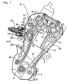
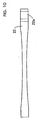
- Fig. 1 is a side view showing a timing transmission gear for a valve gear of an engine provided with a chain tensioner according to the invention
- Fig. 2 is a plan showing a tensioner arm of the chain tensioner
- Fig. 3 is a side view showing the tensioner arm
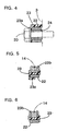
- Fig. 4 is a sectional view viewed along a line 4-4 in Fig. 3
- Fig. 5 is a sectional view viewed along a line 5-5 in Fig. 3
- Fig. 6 is a sectional view viewed along a line 6-6 in Fig.
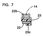
- Fig. 7 is a sectional view viewed along a line 7-7 in Fig.
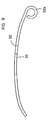
- Fig. 8 is a plan showing the body of the tensioner arm
- Fig. 9 is a side view showing the body of the tensioner arm
- Fig. 10 shows another embodiment of the invention corresponding to Fig. 8.
- an engine E for a motorcycle is arranged in a state in which the head is inclined in front of a vehicle.
- the body Ea of the engine E is composed of a crankcase 1, a cyl inder block 2 and a cyl inder head 3 , a crankshaf t 4 is supported by the crankcase 1, a camshaft for intake air 5 and a camshaft for exhaust 6 are supported by the cylinder head 3, and the crankshaft 4, the camshaft for intake air 5 and the camshaft for exhaust 6 are coupled by a timing transmission gear 10.
- the timing transmission gear 10 is composed of a driving sprocket 11 fixed to the crankshaft 4, first and second driven sprockets 12, 13 respectively fixed to the camshaft for intake air 5 and the camshaft for exhaust 6 and a transmission chain 14 without an end wound on the driving sprocket 11, the first and second driven sprockets 12, 13 .
- the first and second driven sprockets 12, 13 both have double teeth of the number of the teeth of the driving sprocket 11 and are driven in a direction shown by an arrow A at half reduction ratio from the driving sprocket 11.
- a chain tensioner 15 On the loose side of the transmission chain 14, a chain tensioner 15 according to the invention for applying fixed tension to it is arranged.
- the chain tensioner 15 is composed of a tensioner arm 16, a control arm 17 and a tensioner lifter 18.
- the tensioner arm 16 is composed of a band tensioner arm body 22 rockably supported via a first pivot 20 by the cylinder block 2 in the vicinity of the driving sprocket 11 and made of a spring steel plate and curved toward the outside on the loose side of the transmission chain 14 and a tensioner shoe 23 made of flexible synthetic resin that covers the front of the tensioner arm body 22 and is slidingly touched to the outside on the loose side of the transmission chain 14, and as a whole, suitable flexibility that can absorb the oscillation of the transmission chain 14 is applied.
- the tensioner arm body 22 and the tensioner shoe 23 are respectively provided with a boss 22a and a boss 23a supported via a collar 24 by the first pivot 20 at each end, a chain guide groove 23b to which the loose side of the transmission chain 14 is fitted so that the loose side can be slid is formed on the front of the tensioner shoe 23 and at the back of the tensioner shoe, plural holding claws 23c that hold the tensioner arm body 22 lapped over the tensioner shoe are formed.
- an arc-shaped cut-out 25 is formed in the middle from the first pivot 20 to a point N pressed by the control arm 17 on both sides of the tensioner arm body 22 and hereby, the width in the middle of the tensioner arm body 22 is set so that it is smaller than the width at both ends of the arm body 22.
- the control arm 17 is made of a spring steel plate like the tensioner arm body 22 , is supported in the vicinity of the first driven sprocket 12 via a second pivot 21 by the cylinder head 3 so that the control arm can be oscillated and the oscillated end is touched to the back on the side of the oscillated end of the tensioner arm body 22.
- a pressure plate 27 is bonded to the back in the middle of the control arm 17 via cushion material 26 such as rubber and the tensioner lifter 18 for pressing the pressure plate 27 on the side of the tensioner arm 16 is attached to the cylinder head 3.
- a point P of the application of the pressure of the tensioner lifter 18 upon the control arm 17 is set in the middle of the center O of the second pivot 21 which is the center of the oscillation of the control arm 17 and the pressure point N of the control arm 17 upon the tensioner arm 16.
- the control arm 17 is provided with an auxiliary shoe 28 made of synthetic resin and slidingly touched to the outside of the transmission chain 14 between the first driven sprocket 12 and the end of the tensioner arm 16.
- the tensioner lifter 18 is composed of a lifter case 29 fixed to the cylinder head 3 , a hollow lifter rod 3 0 supported by the lifter case 29 so that the rod cannot be turned and opposite to the pressure plate 27, a screw shaft 31 screwed to a hollow part of the lifter rod 30 and a twisted coil spring 32 for turning and pressing the screw shaft 31 in a traveling direction of the lifter rod 30 in the lifter case 29 as heretofore well-known. Therefore, the torsional moment of the twisted coil spring 32 is converted to a thrust load by the screw shaft 31 and is amplified to be pressure that presses the lifter rod 30 on the side of the control arm 17.
- timing transmission gear 10 While the timing transmission gear 10 is operated, that is, when the driving sprocket 11 drives the first and second driven sprockets 12 , 13 via the transmission chain 14, the engaged state of each sprocket 11 to 13 of the transmission chain 14 is always kept suitable and efficient chain transmission is achieved by transmitting pressure which the tensioner lifter 18 applies to the pressure plate 27 of the control arm 17 by the lifter rod 30 to the tensioner arm 16 via the control arm 17, transmitting it to the loose side of the transmission chain 14 and applying fixed tension to the transmission chain 14.
- the oscillation caused during transmission of the transmission chain 14 is effectively absorbed by the suitable deflection of the flexible tensioner arm 16.
- the control arm 17 is inserted between the tensioner arm 16 and the tensioner lifter 18, the repulsion of the transmission chain 14 for the tensioner arm 16 is transmitted to the tensioner lifter 18 after the repulsion is buffered by the suitable deflection of the control arm 17 and a load of the tensioner lifter 18 can be reduced. Therefore, the follow-up of the tensioner lifter 18 for the transmission chain 14 can be satisfactorily performed, securing the desired useful life of the tensioner lifter 18.
- the tensioner arm 16 can be greatly moved via the control arm 17 at a relatively small stroke of the lifter rod 30 of the tensioner lifter 18 owing to the arm ratio of the control arm 17, as a result, the follow-up of the tensioner lifter 18 for the transmission chain 14 is further enhanced, and not only the repulsion of the transmission chain 14 is not directly transmitted to the tensioner lifter 18 but the useful life of the tensioner lifter 18 can be extended.
- control arm 17 presses the auxiliary shoe 28 upon the outside of the transmission chain 14 between the first driven sprocket 12 and the tensioner arm 16 by the pressure of the tensioner lifter 18, contact ratio between the transmission chain 14 and the f irst driven sprocket 12 is enhanced and the control arm contributes to the enhancement of chain transmission efficiency.
- the tensioner arm 16 is composed of the tensioner arm body 22 made of a spring steel plate and the flexible tensioner shoe 23 made of synthetic resin that covers the front of the tensioner arm body 22 and is directly slidingly touched to the transmission chain 14 and the arc-shaped cut-out 25 the width of which is smaller than the width of each end is provided on both sides of the middle of the tensioner arm body 22, the flexibility in the middle of the tensioner arm body 22 is enhanced, the oscillation absorption function for the transmission chain 14 can be enhanced, the natural frequency of the tensioner arm body 22 is different in each part because the width of the tensioner arm body 22 is dif ferent in each part and the tensioner arm can also contribute to the prevention of the resonance of the tensioner arm body 22.
- desired flexibility can be simply applied to the middle of the tensioner arm body 22 by selecting the depth and the number of the cut-outs 25.
- this embodiment is characterized in that the width of a tensioner arm body 22 is gradually reduced from the both ends of the arm body 22 toward the center and as the configuration of the other parts is similar to that in the prior embodiment, the same reference number is allocated to a part corresponding to that in the prior embodiment in Fig. 10 and the description is omitted. According to this embodiment, the similar effect to that in the prior embodiment can be also achieved.
- the invention is not limited to the above-mentioned embodiments and various design changes are possible in a range which does not deviate from the object of the invention.
- the first pivot 20 for supporting the tensioner arm 16 may be also arranged on the side of the first driven sprocket 12 and the second pivot 21 for supporting the control arm 17 may be also arranged on the side of the driving sprocket 11.
- the oscillation of the transmission chain can be absorbed by applying suitable flexibility to the tensioner arm.
- the control arm is inserted between the tensioner arm and the tensioner lifter, the repulsion of the transmission chain for the tensioner arm is transmitted to the tensioner lifter after the repulsion is buffered by the suitable deflection of the control arm and a load of the tensioner lifter can be reduced. Therefore, the follow-up of the tensioner lifter for the transmission chain can be satisfactorily performed, securing the desired useful life of the tensioner lifter.
- the tensioner arm in addition to the first characteristic, as the point of the application of the pressure of the tensioner lifter upon the control arm is set to the middle of the center of the oscillation of the control arm and the point at which the control arm presses the tensioner arm, the tensioner arm can be greatly moved via the control arm at a relatively small stroke of the lifter rod of the tensioner lifter owing to the arm ratio of the control arm, as a result, the follow-up of the tensioner lifter for the transmission chain is further enhanced, and the repulsion of the transmission chain is not directly transmitted to the tensioner lifter but the useful life of the tensioner lifter can be extended.
- the pressing part for slidably pressing the outside of the transmission chain is provided to the control arm between the end of the tensioner arm and the sprocket in the vicinity of the end, the contact ratio of the transmission chain and the driving or driven sprocket close to the end of the tensioner arm is enhanced and chain transmission efficiency can be enhanced.
Abstract
Description
- The present invention relates to the improvement of a chain tensioner provided wi th a tensioner arm rockably supported by fixed structure and slidably touched to the outside on the loose side of a transmission chain without an end coupling a driving sprocket and a driven sprocket and a tensioner lifter supported by fixed structure for pressing the tensioner arm upon the side of the transmission chain.
- Such a chain tensioner is already known as disclosed in a patent document 1 for example.
- Japanese published examined patent application No. Sho63-29963
- In a conventional type chain tensioner, a tensioner lifter directly presses the back of a tensioner arm. To facilitate the absorption of the oscillation of a transmission chain, it is desirable that the flexibility of the tensioner arm is enhanced and its oscillation absorption function is enhanced, however, then, in the conventional type, the tensioner lifter is directly oscillated by the tensioner arm, a load of the tensioner lifter is increased and the follow-up of the tensioner lifter for the transmission chain may be deteriorated.
- The invention is made in view of such a situation and the object is to provide a chain tensioner in which a load of a tensioner lifter is reduced, enhancing the oscillation absorption function of the tensioner lifter and the follow-up of the tensioner lifter for a transmission chain can be satisfactorily maintained.
- To achieve the object, the invention is based upon a chain tensioner provided with a tensioner arm rockably supported by fixed structure and slidably touched to the outside on the loose side of a transmission chain without an end coupling a driving sprocket and a driven sprocket and a tensioner lifter supported by the fixed structure for pressing the tensioner arm upon the side of the transmission chain and is first characterized in that a control arm rockably supported by the fixed structure for transmitting the pressure of the tensioner lifter to the tensioner arm is inserted between the tensioner arm and the tensioner lifter.
- The fixed structure corresponds to an engine body Ea in embodiments described later of the invention.
- According to the first characteristic, the oscillation of the transmission chain can be absorbed by applying suitable flexibility to the tensioner arm. In addition, as the control arm is inserted between the tensioner arm and the tensioner lifter, the repulsion of the transmission chain for the tensioner arm is transmitted to the tensioner lifter after the repulsion is buffered by the suitable flexibility of the control arm and a load of the tensioner lifter can be reduced. Therefore, the follow-up of the transmission chain by the tensioner lifter can be satisfactorily performed, securing the desired useful life of the tensioner lifter.
- Besides, in addition to the first characteristic, the invention is second characterized in that a point of the application of the pressure of the tensioner lifter upon the control arm is set to the middle of the center of the oscillation of the control arm and a point at which the control arm presses the tensioner arm.
- According to the second characteristic, the tensioner arm can be greatly moved via the control arm at a relatively small stroke of a lifter rod of the tensioner lifter owing to the arm ratio of the control arm, as a result, the follow-up of the transmission chain by the tensioner lifter is further enhanced, not only the repulsion of the transmission chain is not directly transmitted to the tensioner lifter but the useful life of the tensioner lifter can be extended.
- Further, in addition to the first or second characteristic, the invention is third characterized in that a pressing part for pressing the outside of the transmission chain so that the pressing part can be slid is provided to the control arm between the end of the tensioner arm and the sprocket in the vicinity of the end.
- The pressing part corresponds to an
auxiliary shoe 28 in an embodiment described later of the invention. - According to the third characteristic, the contact ratio of the transmission chain and the driving or driven sprocket in the vicinity of the end of the tensioner arm is enhanced and the invention can contribute to the enhancement of chain transmission efficiency.
- Preferred embodiments of the present invention will be described hereinafter with reference to the accompanying drawings, in which:
- Fig. 1 is a side view showing a timing transmission gear for a valve gear of an engine provided with a chain tensioner according to the invention;
- Fig. 2 is a plan showing a tensioner arm of the chain tensioner;
- Fig. 3 is a side view showing the tensioner arm;
- Fig. 4 is a sectional view viewed along a line 4-4 in Fig. 3;
- Fig. 5 is a sectional view viewed along a line 5-5 in Fig. 3;
- Fig. 6 is a sectional view viewed along a line 6-6 in Fig. 3;
- Fig. 7 is a sectional view viewed along a line 7-7 in Fig. 3;
- Fig. 8 is a plan showing a tensioner arm body in the tensioner arm;
- Fig. 9 is a side view showing the tensioner arm body; and
- Fig. 10 shows another embodiment of the invention and corresponds to Fig. 8.
-
- Suitable embodiments of the invention shown in the drawings will be described below.
- Fig. 1 is a side view showing a timing transmission gear for a valve gear of an engine provided with a chain tensioner according to the invention, Fig. 2 is a plan showing a tensioner arm of the chain tensioner, Fig. 3 is a side view showing the tensioner arm, Fig. 4 is a sectional view viewed along a line 4-4 in Fig. 3, Fig. 5 is a sectional view viewed along a line 5-5 in Fig. 3, Fig. 6 is a sectional view viewed along a line 6-6 in Fig. 3, Fig. 7 is a sectional view viewed along a line 7-7 in Fig. 3, Fig. 8 is a plan showing the body of the tensioner arm, Fig. 9 is a side view showing the body of the tensioner arm and Fig. 10 shows another embodiment of the invention corresponding to Fig. 8.
- First, as shown in Fig. 1, an engine E for a motorcycle is arranged in a state in which the head is inclined in front of a vehicle. The body Ea of the engine E is composed of a crankcase 1, a
cyl inder block 2 and acyl inder head 3 , acrankshaf t 4 is supported by the crankcase 1, a camshaft forintake air 5 and a camshaft forexhaust 6 are supported by thecylinder head 3, and thecrankshaft 4, the camshaft forintake air 5 and the camshaft forexhaust 6 are coupled by atiming transmission gear 10. - The
timing transmission gear 10 is composed of a drivingsprocket 11 fixed to thecrankshaft 4, first and second drivensprockets intake air 5 and the camshaft forexhaust 6 and atransmission chain 14 without an end wound on the drivingsprocket 11, the first and second drivensprockets sprockets sprocket 11 and are driven in a direction shown by an arrow A at half reduction ratio from the drivingsprocket 11. - On the loose side of the
transmission chain 14, achain tensioner 15 according to the invention for applying fixed tension to it is arranged. - The
chain tensioner 15 is composed of atensioner arm 16, acontrol arm 17 and atensioner lifter 18. - As shown in Figs. 1 to 7, the
tensioner arm 16 is composed of a bandtensioner arm body 22 rockably supported via afirst pivot 20 by thecylinder block 2 in the vicinity of the drivingsprocket 11 and made of a spring steel plate and curved toward the outside on the loose side of thetransmission chain 14 and atensioner shoe 23 made of flexible synthetic resin that covers the front of thetensioner arm body 22 and is slidingly touched to the outside on the loose side of thetransmission chain 14, and as a whole, suitable flexibility that can absorb the oscillation of thetransmission chain 14 is applied. Thetensioner arm body 22 and thetensioner shoe 23 are respectively provided with aboss 22a and aboss 23a supported via acollar 24 by thefirst pivot 20 at each end, achain guide groove 23b to which the loose side of thetransmission chain 14 is fitted so that the loose side can be slid is formed on the front of thetensioner shoe 23 and at the back of the tensioner shoe,plural holding claws 23c that hold thetensioner arm body 22 lapped over the tensioner shoe are formed. - As shown in Figs. 8 and 9, an arc-shaped cut-out 25 is formed in the middle from the
first pivot 20 to a point N pressed by thecontrol arm 17 on both sides of thetensioner arm body 22 and hereby, the width in the middle of thetensioner arm body 22 is set so that it is smaller than the width at both ends of thearm body 22. - As shown in Fig. 1 again, the
control arm 17 is made of a spring steel plate like thetensioner arm body 22 , is supported in the vicinity of the first drivensprocket 12 via asecond pivot 21 by thecylinder head 3 so that the control arm can be oscillated and the oscillated end is touched to the back on the side of the oscillated end of thetensioner arm body 22. Apressure plate 27 is bonded to the back in the middle of thecontrol arm 17 viacushion material 26 such as rubber and thetensioner lifter 18 for pressing thepressure plate 27 on the side of thetensioner arm 16 is attached to thecylinder head 3. - A point P of the application of the pressure of the
tensioner lifter 18 upon thecontrol arm 17 is set in the middle of the center O of thesecond pivot 21 which is the center of the oscillation of thecontrol arm 17 and the pressure point N of thecontrol arm 17 upon thetensioner arm 16. - The
control arm 17 is provided with anauxiliary shoe 28 made of synthetic resin and slidingly touched to the outside of thetransmission chain 14 between the first drivensprocket 12 and the end of thetensioner arm 16. - The
tensioner lifter 18 is composed of alifter case 29 fixed to thecylinder head 3 , ahollow lifter rod 3 0 supported by thelifter case 29 so that the rod cannot be turned and opposite to thepressure plate 27, ascrew shaft 31 screwed to a hollow part of thelifter rod 30 and atwisted coil spring 32 for turning and pressing thescrew shaft 31 in a traveling direction of thelifter rod 30 in thelifter case 29 as heretofore well-known. Therefore, the torsional moment of thetwisted coil spring 32 is converted to a thrust load by thescrew shaft 31 and is amplified to be pressure that presses thelifter rod 30 on the side of thecontrol arm 17. - Next, the action of the embodiment will be described.
- While the
timing transmission gear 10 is operated, that is, when the drivingsprocket 11 drives the first and second drivensprockets transmission chain 14, the engaged state of eachsprocket 11 to 13 of thetransmission chain 14 is always kept suitable and efficient chain transmission is achieved by transmitting pressure which thetensioner lifter 18 applies to thepressure plate 27 of thecontrol arm 17 by thelifter rod 30 to thetensioner arm 16 via thecontrol arm 17, transmitting it to the loose side of thetransmission chain 14 and applying fixed tension to thetransmission chain 14. - The oscillation caused during transmission of the
transmission chain 14 is effectively absorbed by the suitable deflection of theflexible tensioner arm 16. In addition, as thecontrol arm 17 is inserted between thetensioner arm 16 and thetensioner lifter 18, the repulsion of thetransmission chain 14 for thetensioner arm 16 is transmitted to thetensioner lifter 18 after the repulsion is buffered by the suitable deflection of thecontrol arm 17 and a load of thetensioner lifter 18 can be reduced. Therefore, the follow-up of thetensioner lifter 18 for thetransmission chain 14 can be satisfactorily performed, securing the desired useful life of thetensioner lifter 18. - Further, as the point P of the application of the pressure of the
tensioner lifter 18 upon thecontrol arm 17 is set to the middle of the center O of the oscillation of thecontrol arm 17 and the point N at which thecontrol arm 17 presses thetensioner arm 16, thetensioner arm 16 can be greatly moved via thecontrol arm 17 at a relatively small stroke of thelifter rod 30 of thetensioner lifter 18 owing to the arm ratio of thecontrol arm 17, as a result, the follow-up of thetensioner lifter 18 for thetransmission chain 14 is further enhanced, and not only the repulsion of thetransmission chain 14 is not directly transmitted to thetensioner lifter 18 but the useful life of thetensioner lifter 18 can be extended. - Further, as the
control arm 17 presses theauxiliary shoe 28 upon the outside of thetransmission chain 14 between the first drivensprocket 12 and thetensioner arm 16 by the pressure of thetensioner lifter 18, contact ratio between thetransmission chain 14 and the f irst drivensprocket 12 is enhanced and the control arm contributes to the enhancement of chain transmission efficiency. - As the
tensioner arm 16 is composed of thetensioner arm body 22 made of a spring steel plate and theflexible tensioner shoe 23 made of synthetic resin that covers the front of thetensioner arm body 22 and is directly slidingly touched to thetransmission chain 14 and the arc-shaped cut-out 25 the width of which is smaller than the width of each end is provided on both sides of the middle of thetensioner arm body 22, the flexibility in the middle of thetensioner arm body 22 is enhanced, the oscillation absorption function for thetransmission chain 14 can be enhanced, the natural frequency of thetensioner arm body 22 is different in each part because the width of thetensioner arm body 22 is dif ferent in each part and the tensioner arm can also contribute to the prevention of the resonance of thetensioner arm body 22. - In addition, as the width of the
chain guide groove 23b of thetensioner shoe 23 to which thetransmission chain 14 is fitted is fixed overall though surface pressure between thetensioner arm body 22 and thetensioner shoe 23 is large in a location in which the width of thetensioner arm body 22 is small, surface pressure between thetensioner shoe 23 and thetransmission chain 14 is not particularly large, the wear resistance of thetensioner shoe 23 is not damaged and the durability of thetensioner arm 17 can be secured. - Besides, desired flexibility can be simply applied to the middle of the
tensioner arm body 22 by selecting the depth and the number of the cut-outs 25. - Finally, to explain another embodiment shown in Fig. 10 of the invention, this embodiment is characterized in that the width of a
tensioner arm body 22 is gradually reduced from the both ends of thearm body 22 toward the center and as the configuration of the other parts is similar to that in the prior embodiment, the same reference number is allocated to a part corresponding to that in the prior embodiment in Fig. 10 and the description is omitted. According to this embodiment, the similar effect to that in the prior embodiment can be also achieved. - The invention is not limited to the above-mentioned embodiments and various design changes are possible in a range which does not deviate from the object of the invention. For example, in reverse to the above-mentioned embodiments, the
first pivot 20 for supporting thetensioner arm 16 may be also arranged on the side of the first drivensprocket 12 and thesecond pivot 21 for supporting thecontrol arm 17 may be also arranged on the side of the drivingsprocket 11. - As described above, according to the first characteristic of the invention, in the chain tensioner provided with the tensioner arm rockably supported by fixed structure and slidably touched to the outside on the loose side of the transmission chain without an end coupling the driving sprocket and the driven sprocket and the tensioner lifter supported by the fixed structure for pressing the tensioner arm on the side of the transmission chain, as the control arm rockably supported by the fixed structure for transmitting the pressure of the tensioner lifter to the tensioner arm is inserted between the tensioner arm and the tensioner lifter, the oscillation of the transmission chain can be absorbed by applying suitable flexibility to the tensioner arm. In addition, as the control arm is inserted between the tensioner arm and the tensioner lifter, the repulsion of the transmission chain for the tensioner arm is transmitted to the tensioner lifter after the repulsion is buffered by the suitable deflection of the control arm and a load of the tensioner lifter can be reduced. Therefore, the follow-up of the tensioner lifter for the transmission chain can be satisfactorily performed, securing the desired useful life of the tensioner lifter.
- Besides, according to the second characteristic of the invention, in addition to the first characteristic, as the point of the application of the pressure of the tensioner lifter upon the control arm is set to the middle of the center of the oscillation of the control arm and the point at which the control arm presses the tensioner arm, the tensioner arm can be greatly moved via the control arm at a relatively small stroke of the lifter rod of the tensioner lifter owing to the arm ratio of the control arm, as a result, the follow-up of the tensioner lifter for the transmission chain is further enhanced, and the repulsion of the transmission chain is not directly transmitted to the tensioner lifter but the useful life of the tensioner lifter can be extended.
- Further, according to the third characteristic of the invention, in addition to the first or second characteristic, as the pressing part for slidably pressing the outside of the transmission chain is provided to the control arm between the end of the tensioner arm and the sprocket in the vicinity of the end, the contact ratio of the transmission chain and the driving or driven sprocket close to the end of the tensioner arm is enhanced and chain transmission efficiency can be enhanced.
- Subject: To reduce a load of a tensioner lifter, enhancing the oscillation absorption function of the tensioner lifter in a chain tensioner.
- Solving Means: In a chain tensioner provided with a
tensioner arm 16 rockably supported by fixed structure Ea and relatively slidably touched to the outside on the loose side of atransmission chain 14 without an end coupling a drivingsprocket 11 and a drivensprocket 12 and atensioner lifter 18 supported by the fixed structure Ea for pressing thetensioner arm 16 on the side of thetransmission chain 14, acontrol arm 17 rockably supportedby the fixed structure Ea for transmitting the pressure of thetensioner lifter 18 to thetensioner arm 16 is inserted between thetensioner arm 16 and thetensioner lifter 18. -
Claims (3)
- A chain tensioner provided with a tensioner arm (16) rockably supported by fixed structure (Ea) and slidably touched to the outside on the loose side of a transmission chain (14) without an end coupling a driving sprocket (11) and a driven sprocket (12) and a tensioner lifter (18) supported by fixed structure (Ea) for pressing the tensioner arm (16) upon the side of the transmission chain (14), wherein:a control arm (17) rockably supported by fixed structure (Ea) for transmitting the pressure of the tensioner lifter (18) to the tensioner arm (16) is inserted between the tensioner arm (16) and the tensioner lifter (18).
- A chain tensioner according to Claim 1, wherein:a point (P) of the application of the pressure of the tensioner lifter (18) upon the control arm (17) is set to the middle of the center (O) of the oscillation of the control arm (17) and a point (N) at which the control arm (17) presses the tensioner arm (16).
- A chain tensioner according to Claim 1 or 2, wherein:a pressing part (28) slidably touched to the outside of the transmission chain (14) is provided to the control arm (17) between the end of the tensioner arm (16) and the sprocket (12) in the vicinity of the end.
Applications Claiming Priority (2)
| Application Number | Priority Date | Filing Date | Title |
|---|---|---|---|
| JP2002266035 | 2002-09-11 | ||
| JP2002266035A JP4065169B2 (en) | 2002-09-11 | 2002-09-11 | Chain tensioner device |
Publications (3)
| Publication Number | Publication Date |
|---|---|
| EP1398538A2 true EP1398538A2 (en) | 2004-03-17 |
| EP1398538A3 EP1398538A3 (en) | 2008-01-23 |
| EP1398538B1 EP1398538B1 (en) | 2009-12-09 |
Family
ID=31884786
Family Applications (1)
| Application Number | Title | Priority Date | Filing Date |
|---|---|---|---|
| EP03018131A Expired - Lifetime EP1398538B1 (en) | 2002-09-11 | 2003-08-08 | Chain tensioner |
Country Status (9)
| Country | Link |
|---|---|
| US (1) | US7074146B2 (en) |
| EP (1) | EP1398538B1 (en) |
| JP (1) | JP4065169B2 (en) |
| CN (1) | CN1309975C (en) |
| BR (1) | BR0302883B1 (en) |
| CA (1) | CA2436929C (en) |
| DE (1) | DE60330423D1 (en) |
| ES (1) | ES2336088T3 (en) |
| MX (1) | MXPA03007559A (en) |
Cited By (1)
| Publication number | Priority date | Publication date | Assignee | Title |
|---|---|---|---|---|
| WO2007033879A1 (en) * | 2005-09-21 | 2007-03-29 | Schaeffler Kg | Traction mechanism drive for an internal combustion engine |
Families Citing this family (15)
| Publication number | Priority date | Publication date | Assignee | Title |
|---|---|---|---|---|
| JP3999610B2 (en) * | 2002-09-11 | 2007-10-31 | 本田技研工業株式会社 | Chain tensioner device |
| JP2006250208A (en) * | 2005-03-09 | 2006-09-21 | Tsubakimoto Chain Co | Guide for transmission |
| US7641577B2 (en) * | 2005-06-28 | 2010-01-05 | Borgwarner Inc. | Mechanical chain tensioner with compliant blade spring |
| US7628719B2 (en) * | 2005-10-26 | 2009-12-08 | Borgwarner, Inc. | Mechanical strap tensioner for multi-strand tensioning |
| JP4573901B2 (en) | 2008-04-14 | 2010-11-04 | 本田技研工業株式会社 | Chain tensioner device |
| KR100986379B1 (en) | 2008-10-01 | 2010-10-08 | 현대자동차주식회사 | Apparatus for Releasing Tension of Timing Means in Vehicle |
| WO2010059698A1 (en) * | 2008-11-18 | 2010-05-27 | Cloyes Gear And Products, Inc. | Blade tensioner with captured spring |
| JP5143200B2 (en) * | 2009-09-09 | 2013-02-13 | 本田技研工業株式会社 | Chain tensioner device |
| JP2014145398A (en) * | 2013-01-28 | 2014-08-14 | Tsubakimoto Chain Co | Chain guide |
| DE102013004456B3 (en) * | 2013-03-14 | 2014-09-18 | Iwis Motorsysteme Gmbh & Co. Kg | Clamping rail with spring-loaded pressing area |
| US9850989B2 (en) * | 2014-10-22 | 2017-12-26 | Schaeffler Technologies AG & Co. KG | Compliant tensioner arm |
| CN104832611B (en) * | 2015-04-10 | 2017-06-13 | 浙江亚特电器有限公司 | A kind of tool-free auto-tensioning system |
| JP6408974B2 (en) * | 2015-10-21 | 2018-10-17 | 株式会社椿本チエイン | Chain guide |
| CN106051075B (en) * | 2016-07-14 | 2020-02-14 | 广东格兰仕微波炉电器制造有限公司 | Damping structure with transmission |
| JP7260749B2 (en) * | 2019-02-12 | 2023-04-19 | 株式会社椿本チエイン | chain guide |
Citations (2)
| Publication number | Priority date | Publication date | Assignee | Title |
|---|---|---|---|---|
| JPS6329963B2 (en) | 1985-01-14 | 1988-06-16 | Yanmar Agricult Equip | |
| DE19652852A1 (en) | 1995-12-18 | 1997-06-19 | Borg Warner Automotive | Hydraulic chain tensioner |
Family Cites Families (9)
| Publication number | Priority date | Publication date | Assignee | Title |
|---|---|---|---|---|
| JPS57134055A (en) * | 1981-02-10 | 1982-08-19 | Honda Motor Co Ltd | Tensioner device for endless belt |
| JPS59174445U (en) | 1983-05-10 | 1984-11-21 | 本田技研工業株式会社 | Chain tensioner device |
| JPS60155046A (en) * | 1984-01-25 | 1985-08-14 | Borg Warner Ootomooteibu Kk | Pressure urging device for chain tensioner |
| JPH07117129B2 (en) * | 1986-06-24 | 1995-12-18 | ヤマハ発動機株式会社 | Chain guide for overhead camshaft engine |
| JP2843462B2 (en) * | 1992-06-16 | 1999-01-06 | 大同工業株式会社 | Tensioner |
| JPH102386A (en) * | 1996-06-13 | 1998-01-06 | Tsubakimoto Chain Co | Ratchet type tensioner with cushioning mechanism |
| JPH1068452A (en) * | 1996-08-28 | 1998-03-10 | Hokushin Ind Inc | Tensioner of chain |
| US6155941A (en) * | 1998-12-15 | 2000-12-05 | Borgwarner Inc. | Hydraulic tensioner having a flexible blade arm |
| JP4651778B2 (en) * | 2000-06-15 | 2011-03-16 | ボルグワーナー・モールステック・ジャパン株式会社 | Blade tensioner |
-
2002
- 2002-09-11 JP JP2002266035A patent/JP4065169B2/en not_active Expired - Fee Related
-
2003
- 2003-08-08 DE DE60330423T patent/DE60330423D1/en not_active Expired - Lifetime
- 2003-08-08 ES ES03018131T patent/ES2336088T3/en not_active Expired - Lifetime
- 2003-08-08 EP EP03018131A patent/EP1398538B1/en not_active Expired - Lifetime
- 2003-08-11 CA CA002436929A patent/CA2436929C/en not_active Expired - Fee Related
- 2003-08-20 CN CNB031545831A patent/CN1309975C/en not_active Expired - Fee Related
- 2003-08-22 MX MXPA03007559A patent/MXPA03007559A/en active IP Right Grant
- 2003-08-25 US US10/646,741 patent/US7074146B2/en active Active
- 2003-08-25 BR BRPI0302883-6A patent/BR0302883B1/en active IP Right Grant
Patent Citations (2)
| Publication number | Priority date | Publication date | Assignee | Title |
|---|---|---|---|---|
| JPS6329963B2 (en) | 1985-01-14 | 1988-06-16 | Yanmar Agricult Equip | |
| DE19652852A1 (en) | 1995-12-18 | 1997-06-19 | Borg Warner Automotive | Hydraulic chain tensioner |
Cited By (1)
| Publication number | Priority date | Publication date | Assignee | Title |
|---|---|---|---|---|
| WO2007033879A1 (en) * | 2005-09-21 | 2007-03-29 | Schaeffler Kg | Traction mechanism drive for an internal combustion engine |
Also Published As
| Publication number | Publication date |
|---|---|
| CA2436929C (en) | 2006-06-20 |
| CN1493799A (en) | 2004-05-05 |
| US7074146B2 (en) | 2006-07-11 |
| ES2336088T3 (en) | 2010-04-08 |
| EP1398538B1 (en) | 2009-12-09 |
| BR0302883A (en) | 2004-08-24 |
| MXPA03007559A (en) | 2004-03-17 |
| JP2004100886A (en) | 2004-04-02 |
| BR0302883B1 (en) | 2012-07-10 |
| US20040132569A1 (en) | 2004-07-08 |
| DE60330423D1 (en) | 2010-01-21 |
| CN1309975C (en) | 2007-04-11 |
| CA2436929A1 (en) | 2004-03-11 |
| EP1398538A3 (en) | 2008-01-23 |
| JP4065169B2 (en) | 2008-03-19 |
Similar Documents
| Publication | Publication Date | Title |
|---|---|---|
| EP1398538B1 (en) | Chain tensioner | |
| EP1400725B1 (en) | Chain tensioner | |
| US4553509A (en) | Chain drive of a reciprocating-piston internal combustion engine | |
| US20070066428A1 (en) | Traction mechanism | |
| JP4563544B2 (en) | Balancer chain device for engine timing system | |
| JP4755751B2 (en) | Tensioning device | |
| JP3545804B2 (en) | Internal combustion engine with two rows of cylinders | |
| JP2000179633A (en) | Timing system and engine timing system | |
| EP0866241A1 (en) | Guide posts for guiding and damping chain movement | |
| KR100235450B1 (en) | Tensioner | |
| EP1182378A2 (en) | Chain or belt tensioner arm | |
| JP3149876B1 (en) | Chain tensioner device for internal combustion engine | |
| JPH10281244A (en) | Support structure of timing chain guide member of engine | |
| JPH1068452A (en) | Tensioner of chain | |
| JP4919886B2 (en) | Tensioner device | |
| JPH06288446A (en) | Chain tensioner device for engine | |
| JP3755132B2 (en) | Chain blade tensioner system | |
| US7404777B2 (en) | Power transmission incorporating tensioner lever | |
| JP2581022Y2 (en) | Engine accessory drive | |
| JP4274359B2 (en) | Tension device for endless belt for power transmission | |
| JPH08270455A (en) | Chain tensioner for internal combustion engine | |
| JPH10281243A (en) | Chain guide of engine | |
| JPH02283818A (en) | Mounting structure for chain guide | |
| JPH08135464A (en) | Chain tensioner mounting device of internal combustion engine | |
| JPH0211255U (en) |
Legal Events
| Date | Code | Title | Description |
|---|---|---|---|
| PUAI | Public reference made under article 153(3) epc to a published international application that has entered the european phase |
Free format text: ORIGINAL CODE: 0009012 |
|
| AK | Designated contracting states |
Kind code of ref document: A2 Designated state(s): AT BE BG CH CY CZ DE DK EE ES FI FR GB GR HU IE IT LI LU MC NL PT RO SE SI SK TR |
|
| AX | Request for extension of the european patent |
Extension state: AL LT LV MK |
|
| PUAL | Search report despatched |
Free format text: ORIGINAL CODE: 0009013 |
|
| AK | Designated contracting states |
Kind code of ref document: A3 Designated state(s): AT BE BG CH CY CZ DE DK EE ES FI FR GB GR HU IE IT LI LU MC NL PT RO SE SI SK TR |
|
| AX | Request for extension of the european patent |
Extension state: AL LT LV MK |
|
| 17P | Request for examination filed |
Effective date: 20080527 |
|
| AKX | Designation fees paid |
Designated state(s): DE ES FR GB IT |
|
| 17Q | First examination report despatched |
Effective date: 20080911 |
|
| GRAP | Despatch of communication of intention to grant a patent |
Free format text: ORIGINAL CODE: EPIDOSNIGR1 |
|
| GRAS | Grant fee paid |
Free format text: ORIGINAL CODE: EPIDOSNIGR3 |
|
| GRAA | (expected) grant |
Free format text: ORIGINAL CODE: 0009210 |
|
| RIN1 | Information on inventor provided before grant (corrected) |
Inventor name: IBUKURO, HIDEOC/O KABUSHIKI KAISHA HONDA GIJUTSU K Inventor name: FUJIKUBO, MAKOTOC/O KABUSHIKI KAISHA HONDA GIJUTSU Inventor name: FURUYA, MASASHIC/O KABUSHIKI KAISHA HONDA GIJUTSU Inventor name: SONOBATA, AKIRAC/O KABUSHIKI KAISHA HONDA GIJUTSU |
|
| AK | Designated contracting states |
Kind code of ref document: B1 Designated state(s): DE ES FR GB IT |
|
| REG | Reference to a national code |
Ref country code: GB Ref legal event code: FG4D |
|
| REF | Corresponds to: |
Ref document number: 60330423 Country of ref document: DE Date of ref document: 20100121 Kind code of ref document: P |
|
| REG | Reference to a national code |
Ref country code: ES Ref legal event code: FG2A Ref document number: 2336088 Country of ref document: ES Kind code of ref document: T3 |
|
| PLBE | No opposition filed within time limit |
Free format text: ORIGINAL CODE: 0009261 |
|
| STAA | Information on the status of an ep patent application or granted ep patent |
Free format text: STATUS: NO OPPOSITION FILED WITHIN TIME LIMIT |
|
| PGFP | Annual fee paid to national office [announced via postgrant information from national office to epo] |
Ref country code: ES Payment date: 20100915 Year of fee payment: 8 |
|
| 26N | No opposition filed |
Effective date: 20100910 |
|
| PGFP | Annual fee paid to national office [announced via postgrant information from national office to epo] |
Ref country code: GB Payment date: 20100811 Year of fee payment: 8 |
|
| PGFP | Annual fee paid to national office [announced via postgrant information from national office to epo] |
Ref country code: FR Payment date: 20110818 Year of fee payment: 9 |
|
| GBPC | Gb: european patent ceased through non-payment of renewal fee |
Effective date: 20110808 |
|
| PG25 | Lapsed in a contracting state [announced via postgrant information from national office to epo] |
Ref country code: GB Free format text: LAPSE BECAUSE OF NON-PAYMENT OF DUE FEES Effective date: 20110808 |
|
| REG | Reference to a national code |
Ref country code: DE Ref legal event code: R084 Ref document number: 60330423 Country of ref document: DE Effective date: 20120523 |
|
| REG | Reference to a national code |
Ref country code: FR Ref legal event code: ST Effective date: 20130430 |
|
| REG | Reference to a national code |
Ref country code: ES Ref legal event code: FD2A Effective date: 20130606 |
|
| PG25 | Lapsed in a contracting state [announced via postgrant information from national office to epo] |
Ref country code: ES Free format text: LAPSE BECAUSE OF NON-PAYMENT OF DUE FEES Effective date: 20110809 |
|
| PG25 | Lapsed in a contracting state [announced via postgrant information from national office to epo] |
Ref country code: FR Free format text: LAPSE BECAUSE OF NON-PAYMENT OF DUE FEES Effective date: 20120831 |
|
| PGFP | Annual fee paid to national office [announced via postgrant information from national office to epo] |
Ref country code: IT Payment date: 20180621 Year of fee payment: 16 |
|
| PG25 | Lapsed in a contracting state [announced via postgrant information from national office to epo] |
Ref country code: IT Free format text: LAPSE BECAUSE OF NON-PAYMENT OF DUE FEES Effective date: 20190808 |
|
| PGFP | Annual fee paid to national office [announced via postgrant information from national office to epo] |
Ref country code: DE Payment date: 20210630 Year of fee payment: 19 |
|
| REG | Reference to a national code |
Ref country code: DE Ref legal event code: R119 Ref document number: 60330423 Country of ref document: DE |
|
| PG25 | Lapsed in a contracting state [announced via postgrant information from national office to epo] |
Ref country code: DE Free format text: LAPSE BECAUSE OF NON-PAYMENT OF DUE FEES Effective date: 20230301 |