EP1398480A2 - Fuel injection control system for internal combustion engine - Google Patents
Fuel injection control system for internal combustion engine Download PDFInfo
- Publication number
- EP1398480A2 EP1398480A2 EP03018840A EP03018840A EP1398480A2 EP 1398480 A2 EP1398480 A2 EP 1398480A2 EP 03018840 A EP03018840 A EP 03018840A EP 03018840 A EP03018840 A EP 03018840A EP 1398480 A2 EP1398480 A2 EP 1398480A2
- Authority
- EP
- European Patent Office
- Prior art keywords
- injection
- valve
- fuel injection
- fuel
- downstream
- Prior art date
- Legal status (The legal status is an assumption and is not a legal conclusion. Google has not performed a legal analysis and makes no representation as to the accuracy of the status listed.)
- Granted
Links
Images


Classifications
-
- F—MECHANICAL ENGINEERING; LIGHTING; HEATING; WEAPONS; BLASTING
- F02—COMBUSTION ENGINES; HOT-GAS OR COMBUSTION-PRODUCT ENGINE PLANTS
- F02D—CONTROLLING COMBUSTION ENGINES
- F02D41/00—Electrical control of supply of combustible mixture or its constituents
- F02D41/30—Controlling fuel injection
- F02D41/3094—Controlling fuel injection the fuel injection being effected by at least two different injectors, e.g. one in the intake manifold and one in the cylinder
-
- F—MECHANICAL ENGINEERING; LIGHTING; HEATING; WEAPONS; BLASTING
- F02—COMBUSTION ENGINES; HOT-GAS OR COMBUSTION-PRODUCT ENGINE PLANTS
- F02D—CONTROLLING COMBUSTION ENGINES
- F02D41/00—Electrical control of supply of combustible mixture or its constituents
- F02D41/02—Circuit arrangements for generating control signals
- F02D41/04—Introducing corrections for particular operating conditions
- F02D41/10—Introducing corrections for particular operating conditions for acceleration
-
- F—MECHANICAL ENGINEERING; LIGHTING; HEATING; WEAPONS; BLASTING
- F02—COMBUSTION ENGINES; HOT-GAS OR COMBUSTION-PRODUCT ENGINE PLANTS
- F02D—CONTROLLING COMBUSTION ENGINES
- F02D41/00—Electrical control of supply of combustible mixture or its constituents
- F02D41/30—Controlling fuel injection
- F02D41/32—Controlling fuel injection of the low pressure type
- F02D41/34—Controlling fuel injection of the low pressure type with means for controlling injection timing or duration
- F02D41/345—Controlling injection timing
-
- Y—GENERAL TAGGING OF NEW TECHNOLOGICAL DEVELOPMENTS; GENERAL TAGGING OF CROSS-SECTIONAL TECHNOLOGIES SPANNING OVER SEVERAL SECTIONS OF THE IPC; TECHNICAL SUBJECTS COVERED BY FORMER USPC CROSS-REFERENCE ART COLLECTIONS [XRACs] AND DIGESTS
- Y02—TECHNOLOGIES OR APPLICATIONS FOR MITIGATION OR ADAPTATION AGAINST CLIMATE CHANGE
- Y02T—CLIMATE CHANGE MITIGATION TECHNOLOGIES RELATED TO TRANSPORTATION
- Y02T10/00—Road transport of goods or passengers
- Y02T10/10—Internal combustion engine [ICE] based vehicles
- Y02T10/40—Engine management systems
Definitions
- the present invention relates to a fuel injection control system for an internal combustion engine, and more particularly to a fuel injection control system in an internal combustion engine in which respective fuel inj ection valves on the upstream and downstream sides have been arranged with a throttle valve interposed therebetween.
- the volumetric efficiency is improved because heat is taken from intake air when injection fuel vaporizes. Therefore, the engine output can be increased as compared with when the fuel injection valve is provided downstream from the throttle valve.
- Fig. 7 is a cross-sectional view showing a major portion of a conventional internal combustion engine in which two fuel injection valves have been arranged, and with the throttle valve 52 of the intake pipe 51 interposed, there have been arranged a first fuel injection valve 50a on the downstream side and a second fuel injection valve 50b on the upstream side.
- the present invention is characterized in that in a fuel injection system for an internal combustion engine provided with an intake pipe equipped with a throttle valve, an upstream fuel injection valve provided upstream from this throttle valve, and a downstream fuel injection valve provided downstream from the throttle valve, there are included means for controlling fuel injection quantity of each of the fuel injection valves on the basis of plural parameters including throttle opening and engine speed, and means for detecting an accelerated driving state to increase and correct the quantity of injection fuel, and the above-described accelerated increase in quantity and correction increases injection quantity of the downstream fuel injection valve.
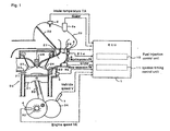
- FIG. 1 is a general block diagram showing a fuel inj action system according to one embodiment of the present invention, and on a combustion chamber 21 of the engine 20, there are opened an intake port 22 and an exhaust port 23.
- Each port 22 and 23 is provided with an intake valve 24 and an exhaust valve 25 respectively, and an ignition plug 26 is provided.
- a throttle valve 28 for adjusting intake air quantity in accordance with its opening ⁇ TH, a throttle sensor 5 for detecting the opening ⁇ TH and a vacuum sensor 6 for detecting intake manifold vacuum PB.
- an air cleaner 29 At a terminal of the intake passage 27, there is provided an air cleaner 29. Within the air cleaner 29, there is provided an air filter 30, and open air is taken into the intake passage 27 through this air filter 30.
- an engine speed sensor 4 for detecting engine speed NE on the basis of a rotation angle of a crank.
- a vehicle speed sensor 7 for detecting vehicle speed V.
- a water temperature sensor 3 for detecting cooling water temperature TW representing the engine temperature.
- An ECU (Engine Control Unit) 1 includes a fuel injection control unit 10 and an ignition timing control unit 11.
- the fuel injection control unit 10 outputs, on the basis of signals (process values) obtained by detecting by each of the above-described sensors, injection signals Qupper and Qlower to each injection valve 8a, 8b on the upstream and downstream sides.
- Each of these injection signals is a pulse signal having pulse width responsive to the injection quantity, and each inj ection valve 8a, 8b is opened by time corresponding to this pulse width to inject the fuel.
- the ignition timing control unit 11 controls ignition timing of an ignition plug 26.
- Fig. 2 is a functional block diagram for the fuel injection control unit 10, and the same symbols as in the foregoing represent the same or equal portions.
- a total injection quantity determination unit 101 determines a total quantity Qtotal of fuel to be injected from each fuel injection valve 8a, 8b on the upstream and downstream sides on the basis of the engine speed NE, the throttle opening ⁇ TH and intake pressure PB.
- An injection rate determination unit 102 refers to an injection rate table on the basis of the engine speed NE and throttle opening ⁇ TH to determine an injection rate Rupper of the upstream injection valve 8a.
- An injection rate Rlower of the downstream injection valve 8b is determined as (1 - Rupper).
- Fig. 3 is a view showing an example of the injection rate table, and in the present embodiment, an injection rate map is constituted with 15 items (Cne00 to Cne14) as a reference as the engine speed NE, and with 10 items (Cth0 to Cth9) as a reference as the throttle opening 6TH, and the injection rate Rupper of the upstream injection valve 8a is registered in advance at each combination of each engine speed NE and the throttle opening ⁇ TH.
- the injection rate determination unit 102 determines an inj ection rate Rupper corresponding to the engine speed NE and the throttle opening ⁇ TH that have been detected, by means of the four-point interpolation on the injection rate map.
- a correction factor calculation unit 103 calculates a manifold air pressure correction factor Kpb, an intake temperature correction factor Kta and cooling water temperature correction factor Ktw and the like on the basis of process values such as the manifold air pressure PB, the intake temperature TA and the cooling water temperature TW, and further calculates a total correction factor Ktotal by integrating these all correction factors.
- An injection quantity correction unit 104 includes an accelerated increase in quantity and correction unit 1041, and during acceleration, increases and corrects the injection quantity of the downstream inj ection valve 8b for acceleration.
- an upstream injection quantity determination unit 1051 determines injection quantity Qupper of the upstream injection valve 8a on the basis of the inj ection rate Rupper and the total inj ection quantity Qtotal .
- a downstream inj ection quantity determination unit 1052 determines the injection quantity Qlower of the downstream injection valve 8b on the basis of theupstreaminjectionquantity Qupper and the total injection quantity Qtotal.
- This handling is executed by interruption due to a crank pulse in a predetermined stage.
- a step S1 the engine speed NE is read in, and in a step S2, the throttle opening ⁇ TH is read in.
- a step S3 an hour rate of change ⁇ TH of the throttle opening ⁇ TH is calculated on the basis of a differential between a previous value for the throttle opening ⁇ TH obtained by detecting in the step S2 and this value.
- the manifold air pressure PB is read in.
- the hour rate of change ⁇ TH of the throttle opening ⁇ TH is compared with a reference rate of change ⁇ THref.
- the sequence will proceed to a step S7 because it is judged that the throttle handling is slow and the engine is in a steady state.
- the PB map is selected by the total injection quantity determination unit 101.
- Fig. 5 is a view showing an example of the PB map, and in the present embodiment, 15 items (Cne00 to Cne14) are defined as the engine speed NE, and 10 items (Cpb0 to Cpb9) are defined as the manifold air pressure PB, and the total injection quantity Qtotal is registered in advance at each combination of each engine speed NE and the manifold air pressure PB.
- the sequence will proceed to a step S6 because the engine is judged to be in a transient state.
- theTHmap is selectedby the total injection quantity determination unit 101.
- Fig. 6 is a view showing an example of the TH map, and in the present embodiment, 15 items (Cne00 to Cne14) are defined as the engine speed NE, and 10 items (Cth0 to Cth9) are defined as the throttle opening 6TH, and the total injection quantity Qtotal is registered in advance at each combination of each engine speed NE and the throttle opening ⁇ TH.
- the PB map 106 is retrieved on the basis of the engine speedNE and the manifold air pressure PB in response to the map selected, or the TH map 107 is retrieved on the basis of the engine speed NE and the throttle opening ⁇ TH to calculate the total injection quantity Qtotal.
- the total injection quantity determination unit 101 determines an injection rate Rupper responsive to the engine speed NE and the throttle opening ⁇ TH (or manifold air pressure PB) detected by means of four-point interpolation on each of the maps.
- the injection rate table is referred to on the basis of the engine speed NE and the throttle opening ⁇ TH, to determine the injection rate Rupper of the upstream injection valve 8a.
- the injection quantity Qlower of the downstream inj ection valve is calculated by adding, to a product of the total injection quantity Qtotal, the downstream injection rate (1 - Rupper) and a total correction factor Ktotal obtained by calculating by the correction factor calculation unit 103, a predetermined accelerated increase quantity value Tacc further obtained by calculating by the accelerated increase in quantity and correction unit 1041 and invalid injection time TiVB.
- the acceleration corrected quantity Tacc is calculated as a function of, for example, the rate of change of the throttle opening ⁇ TH and the manifold air pressure PB.
- the invalid injection time TiVB is time during which of the injection-valve opening time, perfect injection of fuel is not accompanied with, and is determined by type and structure of the fuel injection valve.
- the injection quantity Qupper of theupstream injection valve is calculated by adding, to a product of the total injection quantity Qtotal, the upstream injection rate Rupper and a total correction factor Ktotal obtained by calculating by the correction factor calculation unit 103, further invalid injection time TiVB.
- a driving signal responsive to the upstream injection quantity Qupper and the downstream injection quantity Qlower is supplied to the upstream fuel injection valve 8a and the downstream fuel injection valve 8b. Each fuel injection valve 8a, 8b is opened by time corresponding to the upper injection quantity Qupper and the downstream injection quantity Qlower to inject the fuel.
- the total injection quantity determination unit 101 determines a total quantity Qtotal of fuel to be injected from each fuel injection valve 8a, 8b on the upstream and downstream sides.
- the injection rate determination unit 102 determines an injection rate Rupper of the upstream injection valve 8a.
- the correction factor calculation unit 103 calculates a total correction factor Ktotal.
- the injection quantity correction unit 104 includes an accelerated increase in quantity and correction unit 1041, and during acceleration, increases and corrects only injection quantity of the downstream injection valve 8b for acceleration.
- the inj ection quantity determination unit 105 determines injection quantity Qupper of the upstream injection valve 8a on the basis of the injection rate Rupper and the total injection quantity Qtotal, and determines injection quantity Qlower of the downstream injection valve 8b on the basis of the upstream injection quantity Qupper and the total injection quantity Qtotal.
Landscapes
- Engineering & Computer Science (AREA)
- Chemical & Material Sciences (AREA)
- Combustion & Propulsion (AREA)
- Mechanical Engineering (AREA)
- General Engineering & Computer Science (AREA)
- Electrical Control Of Air Or Fuel Supplied To Internal-Combustion Engine (AREA)
- Combined Controls Of Internal Combustion Engines (AREA)
Abstract
Description
Claims (1)
- A fuel injection control system for an internal combustion engine (20), comprising:characterized in thatin a fuel injection system for an internal combustion engine provided with an intake pipe equipped with a throttle valve (28), an upstream fuel injection valve (8a) provided upstream from said throttle valve (28), and a downstream fuel injection valve (8b) provided downstream from said throttle valve (28),means (101, 102, 105) for controlling fuel injection quantity of each of said fuel injection valves (8a, 8b) on the basis of plural parameters including throttle opening (TH) and engine speed (NE), andmeans (104) for detecting an accelerated driving state to increase and correct the quantity of injection fuel,
said increase in quantity and correction increases injection quantity of said downstream fuel injection valve (8b).
Applications Claiming Priority (2)
| Application Number | Priority Date | Filing Date | Title |
|---|---|---|---|
| JP2002265660 | 2002-09-11 | ||
| JP2002265660A JP3996474B2 (en) | 2002-09-11 | 2002-09-11 | Fuel injection control device for internal combustion engine |
Publications (3)
| Publication Number | Publication Date |
|---|---|
| EP1398480A2 true EP1398480A2 (en) | 2004-03-17 |
| EP1398480A3 EP1398480A3 (en) | 2006-06-28 |
| EP1398480B1 EP1398480B1 (en) | 2012-06-06 |
Family
ID=31884778
Family Applications (1)
| Application Number | Title | Priority Date | Filing Date |
|---|---|---|---|
| EP03018840A Expired - Lifetime EP1398480B1 (en) | 2002-09-11 | 2003-08-19 | Fuel injection control system for internal combustion engine |
Country Status (4)
| Country | Link |
|---|---|
| US (1) | US6848428B2 (en) |
| EP (1) | EP1398480B1 (en) |
| JP (1) | JP3996474B2 (en) |
| ES (1) | ES2386632T3 (en) |
Cited By (1)
| Publication number | Priority date | Publication date | Assignee | Title |
|---|---|---|---|---|
| EP1803924A3 (en) * | 2005-12-28 | 2011-06-15 | Honda Motor Co., Ltd. | Fuel injection system for engine |
Family Cites Families (14)
| Publication number | Priority date | Publication date | Assignee | Title |
|---|---|---|---|---|
| JPS608339B2 (en) * | 1979-01-23 | 1985-03-02 | トヨタ自動車株式会社 | Fuel injection method for fuel-injected internal combustion engines |
| JPS59134363A (en) * | 1983-01-20 | 1984-08-02 | Nippon Soken Inc | Fuel feeder for internal-combustion engine |
| US4612904A (en) * | 1983-02-15 | 1986-09-23 | Mazda Motor Corporation | Fuel injection system for internal combustion engines |
| US4819604A (en) * | 1986-12-10 | 1989-04-11 | Honda Giken Kogyo Kabushiki Kaisha | Fuel supply control method for internal combustion engines |
| US4825834A (en) * | 1986-12-10 | 1989-05-02 | Honda Giken Kogyo Kabushiki Kaisha | Fuel supply control method for internal combustion engines |
| JPH0799110B2 (en) * | 1987-08-17 | 1995-10-25 | 本田技研工業株式会社 | Air-fuel ratio feedback control method for internal combustion engine |
| JPH0249940A (en) * | 1988-08-11 | 1990-02-20 | Japan Electron Control Syst Co Ltd | Internal combustion engine fuel supply control device |
| JPH04183949A (en) * | 1990-11-19 | 1992-06-30 | Mazda Motor Corp | Engine fuel control device |
| JPH04191446A (en) * | 1990-11-22 | 1992-07-09 | Mazda Motor Corp | Fuel control device of engine |
| JP3333941B2 (en) * | 1992-02-06 | 2002-10-15 | マツダ株式会社 | Engine control device |
| US5284117A (en) * | 1992-04-27 | 1994-02-08 | Mitsubishi Denki Kabushiki Kaisha | Fuel supply apparatus for an internal combustion engine |
| JP3886193B2 (en) * | 1997-01-14 | 2007-02-28 | 本田技研工業株式会社 | Fuel injection device |
| SE522625C2 (en) * | 2000-04-19 | 2004-02-24 | Sem Ab | Methods and apparatus for internal combustion engine |
| JP4509420B2 (en) * | 2001-05-21 | 2010-07-21 | 本田技研工業株式会社 | Engine fuel injection control device |
-
2002
- 2002-09-11 JP JP2002265660A patent/JP3996474B2/en not_active Expired - Fee Related
-
2003
- 2003-08-19 EP EP03018840A patent/EP1398480B1/en not_active Expired - Lifetime
- 2003-08-19 ES ES03018840T patent/ES2386632T3/en not_active Expired - Lifetime
- 2003-08-25 US US10/646,740 patent/US6848428B2/en not_active Expired - Lifetime
Cited By (1)
| Publication number | Priority date | Publication date | Assignee | Title |
|---|---|---|---|---|
| EP1803924A3 (en) * | 2005-12-28 | 2011-06-15 | Honda Motor Co., Ltd. | Fuel injection system for engine |
Also Published As
| Publication number | Publication date |
|---|---|
| JP2004100619A (en) | 2004-04-02 |
| ES2386632T3 (en) | 2012-08-24 |
| EP1398480A3 (en) | 2006-06-28 |
| US20040069283A1 (en) | 2004-04-15 |
| EP1398480B1 (en) | 2012-06-06 |
| JP3996474B2 (en) | 2007-10-24 |
| US6848428B2 (en) | 2005-02-01 |
Similar Documents
| Publication | Publication Date | Title |
|---|---|---|
| EP1437498B1 (en) | 4−STROKE ENGINE CONTROL DEVICE AND CONTROL METHOD | |
| JP3976322B2 (en) | Engine control device | |
| US7100572B2 (en) | Fuel injection system and fuel injecting method for internal combustion engine | |
| EP1396633B1 (en) | Fuel injection system for internal combustion engine | |
| JPH06159114A (en) | Air-fuel ratio controller for internal combustion engine | |
| EP1398480B1 (en) | Fuel injection control system for internal combustion engine | |
| JP2002147269A (en) | Engine control device | |
| JP2812048B2 (en) | Electronic control unit for internal combustion engine | |
| CA2436968C (en) | Fuel injection system for internal combustion engine | |
| US7011604B2 (en) | Fuel injection control system for internal combustion engine | |
| JP3838526B2 (en) | Fuel injection control device and fuel injection control method for internal combustion engine | |
| EP1396628B1 (en) | Fuel injection system for internal combustion engine | |
| JPH0681914B2 (en) | Electronic control unit for internal combustion engine | |
| JP3397584B2 (en) | Electric throttle type internal combustion engine | |
| JP2004100589A (en) | Fuel injection device for internal combustion engine | |
| JPH06272601A (en) | Engine controller | |
| JPS61101634A (en) | Air-fuel ratio controlling method for internal-combustion engine | |
| JP2002317675A (en) | Air-fuel ratio control device for internal combustion engine | |
| JPH02104934A (en) | Fuel injection device for engine | |
| JPS63255540A (en) | Fuel control device of engine |
Legal Events
| Date | Code | Title | Description |
|---|---|---|---|
| PUAI | Public reference made under article 153(3) epc to a published international application that has entered the european phase |
Free format text: ORIGINAL CODE: 0009012 |
|
| AK | Designated contracting states |
Kind code of ref document: A2 Designated state(s): AT BE BG CH CY CZ DE DK EE ES FI FR GB GR HU IE IT LI LU MC NL PT RO SE SI SK TR |
|
| AX | Request for extension of the european patent |
Extension state: AL LT LV MK |
|
| PUAL | Search report despatched |
Free format text: ORIGINAL CODE: 0009013 |
|
| AK | Designated contracting states |
Kind code of ref document: A3 Designated state(s): AT BE BG CH CY CZ DE DK EE ES FI FR GB GR HU IE IT LI LU MC NL PT RO SE SI SK TR |
|
| AX | Request for extension of the european patent |
Extension state: AL LT LV MK |
|
| 17P | Request for examination filed |
Effective date: 20060622 |
|
| AKX | Designation fees paid |
Designated state(s): DE ES FR GB IT |
|
| 17Q | First examination report despatched |
Effective date: 20101129 |
|
| GRAP | Despatch of communication of intention to grant a patent |
Free format text: ORIGINAL CODE: EPIDOSNIGR1 |
|
| GRAS | Grant fee paid |
Free format text: ORIGINAL CODE: EPIDOSNIGR3 |
|
| GRAA | (expected) grant |
Free format text: ORIGINAL CODE: 0009210 |
|
| RIN1 | Information on inventor provided before grant (corrected) |
Inventor name: WATANABE, TSUGUO Inventor name: MACHIDA, KENICHI Inventor name: HAYASHI, TATSUO Inventor name: YUHARA, TOMOMI |
|
| AK | Designated contracting states |
Kind code of ref document: B1 Designated state(s): DE ES FR GB IT |
|
| REG | Reference to a national code |
Ref country code: GB Ref legal event code: FG4D |
|
| RIN2 | Information on inventor provided after grant (corrected) |
Inventor name: MACHIDA, KENICHI Inventor name: WATANABE, TSUGUO Inventor name: YUHARA, TOMOMI Inventor name: HAYASHI, TATSUO |
|
| REG | Reference to a national code |
Ref country code: DE Ref legal event code: R096 Ref document number: 60341121 Country of ref document: DE Effective date: 20120809 |
|
| REG | Reference to a national code |
Ref country code: ES Ref legal event code: FG2A Ref document number: 2386632 Country of ref document: ES Kind code of ref document: T3 Effective date: 20120824 |
|
| PLBE | No opposition filed within time limit |
Free format text: ORIGINAL CODE: 0009261 |
|
| STAA | Information on the status of an ep patent application or granted ep patent |
Free format text: STATUS: NO OPPOSITION FILED WITHIN TIME LIMIT |
|
| 26N | No opposition filed |
Effective date: 20130307 |
|
| REG | Reference to a national code |
Ref country code: DE Ref legal event code: R097 Ref document number: 60341121 Country of ref document: DE Effective date: 20130307 |
|
| REG | Reference to a national code |
Ref country code: FR Ref legal event code: PLFP Year of fee payment: 14 |
|
| REG | Reference to a national code |
Ref country code: FR Ref legal event code: PLFP Year of fee payment: 15 |
|
| PGFP | Annual fee paid to national office [announced via postgrant information from national office to epo] |
Ref country code: FR Payment date: 20170714 Year of fee payment: 15 Ref country code: GB Payment date: 20170816 Year of fee payment: 15 Ref country code: IT Payment date: 20170824 Year of fee payment: 15 Ref country code: ES Payment date: 20170901 Year of fee payment: 15 |
|
| PGFP | Annual fee paid to national office [announced via postgrant information from national office to epo] |
Ref country code: DE Payment date: 20180807 Year of fee payment: 16 |
|
| GBPC | Gb: european patent ceased through non-payment of renewal fee |
Effective date: 20180819 |
|
| PG25 | Lapsed in a contracting state [announced via postgrant information from national office to epo] |
Ref country code: IT Free format text: LAPSE BECAUSE OF NON-PAYMENT OF DUE FEES Effective date: 20180819 |
|
| PG25 | Lapsed in a contracting state [announced via postgrant information from national office to epo] |
Ref country code: FR Free format text: LAPSE BECAUSE OF NON-PAYMENT OF DUE FEES Effective date: 20180831 |
|
| REG | Reference to a national code |
Ref country code: ES Ref legal event code: FD2A Effective date: 20190918 |
|
| PG25 | Lapsed in a contracting state [announced via postgrant information from national office to epo] |
Ref country code: ES Free format text: LAPSE BECAUSE OF NON-PAYMENT OF DUE FEES Effective date: 20180820 Ref country code: GB Free format text: LAPSE BECAUSE OF NON-PAYMENT OF DUE FEES Effective date: 20180819 |
|
| REG | Reference to a national code |
Ref country code: DE Ref legal event code: R119 Ref document number: 60341121 Country of ref document: DE |
|
| PG25 | Lapsed in a contracting state [announced via postgrant information from national office to epo] |
Ref country code: DE Free format text: LAPSE BECAUSE OF NON-PAYMENT OF DUE FEES Effective date: 20200303 |