EP1398271A1 - Method and conveyor for conveying articles - Google Patents
Method and conveyor for conveying articles Download PDFInfo
- Publication number
- EP1398271A1 EP1398271A1 EP03103330A EP03103330A EP1398271A1 EP 1398271 A1 EP1398271 A1 EP 1398271A1 EP 03103330 A EP03103330 A EP 03103330A EP 03103330 A EP03103330 A EP 03103330A EP 1398271 A1 EP1398271 A1 EP 1398271A1
- Authority
- EP
- European Patent Office
- Prior art keywords
- conveyor
- flaps
- article
- blank
- Prior art date
- Legal status (The legal status is an assumption and is not a legal conclusion. Google has not performed a legal analysis and makes no representation as to the accuracy of the status listed.)
- Granted
Links
Images


Classifications
-
- B—PERFORMING OPERATIONS; TRANSPORTING
- B65—CONVEYING; PACKING; STORING; HANDLING THIN OR FILAMENTARY MATERIAL
- B65B—MACHINES, APPARATUS OR DEVICES FOR, OR METHODS OF, PACKAGING ARTICLES OR MATERIALS; UNPACKING
- B65B43/00—Forming, feeding, opening or setting-up containers or receptacles in association with packaging
- B65B43/08—Forming three-dimensional [3D] containers from sheet material
- B65B43/10—Forming three-dimensional [3D] containers from sheet material by folding the material
-
- B—PERFORMING OPERATIONS; TRANSPORTING
- B65—CONVEYING; PACKING; STORING; HANDLING THIN OR FILAMENTARY MATERIAL
- B65B—MACHINES, APPARATUS OR DEVICES FOR, OR METHODS OF, PACKAGING ARTICLES OR MATERIALS; UNPACKING
- B65B19/00—Packaging rod-shaped or tubular articles susceptible to damage by abrasion or pressure, e.g. cigarettes, cigars, macaroni, spaghetti, drinking straws or welding electrodes
- B65B19/02—Packaging cigarettes
- B65B19/22—Wrapping the cigarettes; Packaging the cigarettes in containers formed by folding wrapping material around formers
- B65B19/228—Preparing and feeding blanks
-
- B—PERFORMING OPERATIONS; TRANSPORTING
- B65—CONVEYING; PACKING; STORING; HANDLING THIN OR FILAMENTARY MATERIAL
- B65B—MACHINES, APPARATUS OR DEVICES FOR, OR METHODS OF, PACKAGING ARTICLES OR MATERIALS; UNPACKING
- B65B43/00—Forming, feeding, opening or setting-up containers or receptacles in association with packaging
- B65B43/12—Feeding flexible bags or carton blanks in flat or collapsed state; Feeding flat bags connected to form a series or chain
- B65B43/14—Feeding individual bags or carton blanks from piles or magazines
- B65B43/16—Feeding individual bags or carton blanks from piles or magazines by grippers
- B65B43/18—Feeding individual bags or carton blanks from piles or magazines by grippers by suction-operated grippers
- B65B43/185—Feeding individual bags or carton blanks from piles or magazines by grippers by suction-operated grippers specially adapted for carton blanks
Definitions
- the present invention relates to a method of conveying articles.
- the present invention relates to a method of conveying blanks by which to produce packets of cigarettes, to which the present invention refers purely by way of example.
- Blanks are normally supplied successively to respective pockets on a packing machine conveyor, and are fed along a given path, along which, they are paired with respective groups of cigarettes wrapped beforehand in sheets of foil. Once paired with a respective group, the blank is folded about the group by folding members on the packing machine.
- the blank is made of cardboard, and comprises tabs and flaps defined by cuts and crease lines.
- the crease lines are defined by incisions made in the cardboard, and which act as hinges about which the tabs and flaps are folded.
- each blank be set to a given position with respect to the group and the folding members to prevent the group from being placed on the crease lines, or the folding members from folding portions of the blank not meant to be folded.
- a method of conveying articles comprising the steps of feeding an article to a pocket travelling along a given path; retaining said article by gripping means associated with said pocket; and feeding the article along said path in a given direction by means of said pocket; the method being characterized by releasing said article from said gripping means, and pushing the article against a locating member of said pocket as said article is advanced.
- the present invention also relates to a conveyor for conveying articles.
- a conveyor for conveying articles comprising a pocket movable in a direction along a given path, and gripping means associated with said pocket to retain said article; and the conveyor being characterized by comprising folding devices located along the path and cooperating with said gripping means and with a locating member associated with said pocket.
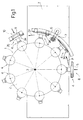
- Number 1 in Figure 1 indicates as a whole a conveyor of a packing machine (not shown) for packing cigarettes (not shown).
- Conveyor 1 is supported by a frame T, and comprises a drum 2 rotating about an axis 3; a number of gripping members 4 equally spaced about axis 3 (perpendicular to the Figure 1 plane) and movable in a direction D1 along a conveying path P of cardboard blanks 5; a guide 6 parallel to a portion of path P; and folding members 7 located along path P at guide 6.
- Each blank 5 is fed to a gripping member 4 of conveyor 1 at a feed station 8 located upstream from guide 6 in direction D1, and is paired with a group 9 of cigarettes, wrapped beforehand in a sheet of foil, at a pairing station 10 located downstream from guide 6 in direction D1.
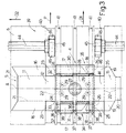
- blank 5 when flat, extends along and is symmetrical with respect to an axis A, and comprises a front panel 11, a bottom panel 12, a rear panel 13, a top panel 14; and a front lid panel 15.
- Tabs 16, 17, 18, 19 and 20 extend from panels 11, 13 and 15; panels 11-15 and tabs 16-20 are bounded by crease lines 21 parallel to axis A, and by crease lines 22 perpendicular to axis A; and a flap 23 extends from each tab 17, and is bounded with respect to tab 17 by a crease line 24.
- a flap 25 extends from each tab 18, and is bounded with respect to tab 18 by a crease line 26.
- Crease lines 21, 22, 24 and 26 are substantially incisions made in the cardboard of blank 5, and serve to fold panels 11-15, tabs 16-20, and flaps 23 and 25 easily with respect to adjacent panels 11-15 and/or tabs 17 and 18. In other words, crease lines 21, 22, 24 and 26 act as hinges.
- each gripping member 4 comprises a rod 27 connected to drum 2; a plate 28 fitted to rod 27 and having suction holes 29; two folding devices 30 and 31 hinged to plate 28 about respective axes 32 and 33 parallel to axis 3; and a locating member 34 integral with plate 28.
- Gripping member 4 comprises known mechanisms, not shown, for rotating the two folding devices 30 and 31 about respective axes 32 and 33. That is, member 4 comprises a variable-configuration pocket 35 defined by plate 28 and the two folding devices 30 and 31, which can be positioned substantially coplanar with plate 28, perpendicular to plate 28, or in intermediate positions between the coplanar and perpendicular positions.
- Locating member 34 comprises three teeth 36 located downstream from plate 28 in direction D1, and each having a free end 37 bent outwards of drum 2 and engaging a respective opening 38 in folding device 31.
- Guide 6 is in the form a cylindrical shell sector, which has an inner face 39 facing drum 2.
- Two grooves 40 are formed along face 39, extend parallel to path P, and provide for housing flaps 23 and 25 folded with respect to the rest of blank 5, and part of folding member 7; and three grooves 41 are also formed along face 39, extend parallel to path P, between grooves 40, and provide for housing ends 37 of teeth 36. That is, face 39 faces plates 28 of gripping members 4 travelling along guide 6.
- folding member 7 comprises a drive member 42; a shaft 43 parallel to axis 3 and rotated by drive member 42; and two shafts 44 parallel to and rotated by shaft 43, and having a folding devices 45 having lobes 46 for squarely folding flaps 23 and 25.
- Each folding device 45 is located between guide 6 and drum 2, and is synchronized with pockets 35 so that each lobe 46 folds a respective flap 23 or 25.
- each blank 5 is fed to a respective pocket 35 at feed station 8, and is gripped by plate 28 by means of suction holes 29, as shown in Figure 1.
- the blank 5 feed step comprises seating blank 5 inside the open pocket 35 with axis A of blank 5 substantially parallel to axis 3 of drum 2, with panel 13 on plate 28, and with tabs 17 and 18 at the two folding devices 30 and 31.
- Drum 2 is rotated continuously, and blank 5 is fed to pocket 35 without stopping gripping member 4 at feed station 8, so that blank 5 is positioned substantially accurately in a direction parallel to axis 3, but not so in travelling direction D1.
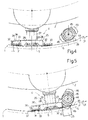
- Flaps 23 and 25 total four in number, and comprise two front flaps 23 and 25, i.e. upstream from plate 28 in direction D1 and two rear flaps 23 and 25, i.e. downstream from plate 28 in direction D1. More specifically, and with reference to Figure 4, lobes 46 are timed with front flaps 23 and 25 of a blank 5 theoretically positioned correctly. In Figure 5, lobes 46 gradually come into contact with and begin folding front flaps 23 and 25 about lines 24 and 26. At this stage, even if blank 5 is still some distance from ends 37, i.e. is not positioned correctly inside pocket 35, blank 5 is pushed against ends 37 by lobes 46 as they begin folding front flaps 23 and 25.
- both lobes 46 act simultaneously on the two front flaps 23 and 25, there is no danger of misalignment of axis A of blank 5 with respect to axis 3 of drum 2.
- the suction through holes 29 is reactivated to grip blank 5 in the definitely correct position, so that lobes 46, as shown in Figure 6, are timed with the two rear flaps 23 and 25, which are folded squarely with respect to the rest of blank 5.
- a group 9 is paired with blank 5 at station 10, and tabs 17 and 18 are folded by folding devices 30 and 31, together with flaps 23 and 25 already folded squarely with respect to tabs 17 and 18.
- folding devices 45 therefore also act as contrasting members by which to push blank 5 against locating member 34.
Landscapes
- Engineering & Computer Science (AREA)
- Mechanical Engineering (AREA)
- Making Paper Articles (AREA)
- Wrapping Of Specific Fragile Articles (AREA)
- Intermediate Stations On Conveyors (AREA)
- Specific Conveyance Elements (AREA)
- Structure Of Belt Conveyors (AREA)
- Chain Conveyers (AREA)
Abstract
Description
Claims (25)
- A method of conveying articles, comprising the steps of feeding an article (5) to a pocket (35) travelling along a given path (P); retaining said article (5) by gripping means (28, 29) associated with said pocket (35); and feeding the article (5) along said path (P) in a given direction (D1) by means of said pocket (35); the method being characterized by releasing said article (5) from said gripping means (28, 29), and pushing the article (5) against a locating member (34) of said pocket (35) as said article (5) is advanced.
- A method as claimed in Claim 1, characterized by retaining the article (5) by means of said gripping means (28, 29) once the article (5) rests against said locating member (34).
- A method as claimed in Claim 1 or 2, characterized in that said locating member (34) is located downstream from the gripping means (28, 29) with respect to the feed direction (D1).
- A method as claimed in Claim 3, characterized by pushing said article (5) against said locating member (34) by means of push means (45) located along said path (P) .
- A method as claimed in Claim 4, characterized in that said push means are folding devices (45).
- A method as claimed in Claim 5, characterized in that said articles are blanks (5); each blank (5) comprising panels (11, 12, 13, 14, 15), tabs (16, 17, 18, 19, 20) and flaps (23, 25).
- A method as claimed in Claim 6, characterized in that the tabs (16, 17, 18, 19, 20) are bounded with respect to the panels (11, 12, 13, 14, 15) by first crease lines (21, 22), and the flaps (23, 25) are bounded with respect to the tabs (17, 18) by second crease lines (24, 26); said second crease lines (24, 26) being substantially parallel to the feed direction (D1) .
- A method as claimed in Claim 7, characterized in that the blank (5) has a longitudinal axis (A) ; the method conveying each blank (5) with its longitudinal axis (A) crosswise to the feed direction (D1).
- A method as claimed in Claim 7 or 8, characterized in that said blank (5) comprises a first pair of flaps (23, 25) upstream with respect to the respective pocket (35), and a second pair of flaps (23, 25) downstream with respect to the pocket (35); the method folding the first pair of flaps (23, 25) by means of said folding devices (45) when said blank (5) is released from said gripping means (28, 29).
- A method as claimed in Claim 9, characterized by folding the second pair of flaps (23, 25) by means of said folding devices (45) when the blank (5) is retained by said gripping means (28, 29).
- A method as claimed in any one of Claims 1 to 10, characterized by feeding each article (5) between the respective pocket (35) and a guide (6), located along a portion of the path (P), when said gripping means (28, 29) are deactivated.
- A conveyor for conveying articles (5), the conveyor comprising a pocket (35) movable in a direction (D1) along a given path (P), and gripping means (28, 29) associated with said pocket (35) to retain said article (5); and the conveyor being characterized by comprising folding devices (45) located along the path (P) and cooperating with said gripping means (28, 29) and with a locating member (34) associated with said pocket (35).
- A conveyor as claimed in Claim 12, characterized in that said locating member (34) is located downstream with respect to the gripping means (28, 29).
- A conveyor as claimed in Claim 13, characterized in that said locating member (34) comprises stop members (37) for said article (5).
- A conveyor as claimed in any one of Claims 12 to 14, characterized in that said folding devices (45) are rotary folding devices (45) selectively positioned contacting said article (5).
- A conveyor as claimed in Claim 15, characterized in that said folding devices (45) rotate about an axis (44) perpendicular to said direction (D1) .
- A conveyor as claimed in Claim 16, characterized in that said articles are blanks (5); each blank (5) comprising panels (11, 12, 13, 14, 15), tabs (16, 17, 18, 19, 20) and flaps (23, 25); said folding devices (45) folding said flaps (23, 25) with respect to the rest of the blank (5); and said gripping means (28, 29) comprising a plate (28) and suction holes (29) for retaining one (13) of said panels (11, 12, 13, 14, 15).
- A conveyor as claimed in Claim 17, characterized in that the tabs (16, 17, 18, 19, 20) are bounded with respect to the panels (11, 12, 13, 14, 15) by first crease lines (21, 22), and the flaps (23, 25) are bounded with respect to the tabs (17, 18) by second crease lines (24, 26); said pocket (35) retaining said blank (5) with said second crease lines (24, 26) substantially parallel to said direction (D1).
- A conveyor as claimed in Claim 18 or 19, characterized in that said blank (5) comprises a first pair of flaps (23, 25) upstream with respect to the respective pocket (35), and a second pair of flaps (23, 25) downstream with respect to the pocket (35); each folding device (45) comprising a first lobe (46) for folding a flap in the first pair of flaps (23, 25), and a second lobe (46) for folding a flap in the second pair of flaps (23, 25) .
- A conveyor as claimed in any one of Claims 12 to 19, characterized by comprising a guide (6) located along a portion of the path (P).
- A conveyor as claimed in Claim 20, characterized by comprising a drum (2) rotating about an axis (3) of rotation and having a number of gripping members (4) equally spaced about the axis (3) of rotation; each gripping member (4) having a said pocket (35) .
- A conveyor as claimed in Claim 21, characterized in that said guide (6) comprises a face (39) facing said drum (2) .
- A conveyor as claimed in Claim 22, characterized in that said folding devices (45) are located between the guide (6) and the drum (2).
- A conveyor as claimed in Claim 22, characterized in that said guide comprises first grooves (40) extending parallel to the path (P) along said face (39) and for housing the folded flaps (23, 25).
- A conveyor as claimed in any one of Claims 22 to 24, characterized in that said guide (6) comprises second grooves (41) extending parallel to the path (P) and for partly housing the locating member (34).
Applications Claiming Priority (2)
| Application Number | Priority Date | Filing Date | Title |
|---|---|---|---|
| IT000570A ITBO20020570A1 (en) | 2002-09-10 | 2002-09-10 | METHOD AND CONVEYOR FOR ADVANCING ITEMS. |
| ITBO20020570 | 2002-09-10 |
Publications (2)
| Publication Number | Publication Date |
|---|---|
| EP1398271A1 true EP1398271A1 (en) | 2004-03-17 |
| EP1398271B1 EP1398271B1 (en) | 2007-04-25 |
Family
ID=31726536
Family Applications (1)
| Application Number | Title | Priority Date | Filing Date |
|---|---|---|---|
| EP03103330A Expired - Lifetime EP1398271B1 (en) | 2002-09-10 | 2003-09-09 | Method and conveyor for conveying articles |
Country Status (7)
| Country | Link |
|---|---|
| US (1) | US20040144621A1 (en) |
| EP (1) | EP1398271B1 (en) |
| JP (1) | JP4541669B2 (en) |
| CN (1) | CN1318267C (en) |
| AT (1) | ATE360574T1 (en) |
| DE (1) | DE60313408T2 (en) |
| IT (1) | ITBO20020570A1 (en) |
Citations (3)
| Publication number | Priority date | Publication date | Assignee | Title |
|---|---|---|---|---|
| DE1511585A1 (en) * | 1966-04-16 | 1969-09-11 | Focke Pfuhl Verpack Automat | Device for U-shaped folding of, in particular, foil blanks around packs |
| EP0806350A1 (en) * | 1996-05-06 | 1997-11-12 | G.D Societa' Per Azioni | Product manipulating method |
| EP0970885A1 (en) * | 1998-07-06 | 2000-01-12 | G. D Societa per Azioni | Unit for supplying blanks on a packing machine |
Family Cites Families (15)
| Publication number | Priority date | Publication date | Assignee | Title |
|---|---|---|---|---|
| US1992347A (en) * | 1934-01-02 | 1935-02-26 | Rosenberg Bros & Co | Nut branding machine |
| GB1171762A (en) * | 1965-11-01 | 1969-11-26 | Molins Machine Co Ltd | Improvements in or relating to Packing Machines. |
| US3556281A (en) * | 1968-11-05 | 1971-01-19 | George W Ashlock Co | Apparatus and method for handling and pitting prunes |
| DE3802644C2 (en) * | 1988-01-29 | 1999-10-07 | Focke & Co | Method and device for manufacturing folding boxes for cigarettes |
| IT1225504B (en) * | 1988-11-30 | 1990-11-20 | Gd Spa | METHOD FOR PACKAGING CIGARETTES IN RIGID HINGED LID PACKAGES |
| GB8924078D0 (en) * | 1989-10-26 | 1989-12-13 | Tetra Pak Ab | Continuous to intermittent feeding interface |
| IT1280369B1 (en) * | 1995-02-21 | 1998-01-20 | Gd Spa | CONTINUOUS CIGARETTE PACKING MACHINE |
| IT1281260B1 (en) * | 1995-04-27 | 1998-02-17 | Sasib Spa | METHOD AND DEVICE FOR PACKAGING PRODUCTS, IN PARTICULAR ASTIFORM, SUCH AS CIGARETTES, OR SIMILAR IN A PACKING SHEET |
| US5577439A (en) * | 1996-03-22 | 1996-11-26 | Ashlock Company, A Division Of Vistan Corporation | Apparatus for pitting prunes or dates |
| EP0820929A1 (en) * | 1996-07-26 | 1998-01-28 | G.D Societa' Per Azioni | Packet wrapping unit |
| DE19649543A1 (en) * | 1996-11-29 | 1998-06-04 | Focke & Co | Packaging machine with folding turret for the manufacture of (soft) cup packs for cigarettes |
| DE19720500A1 (en) * | 1997-05-16 | 1998-11-19 | Topack Verpacktech Gmbh | Method and device for folding the top flap of a blank for a cigarette packet |
| IT1309034B1 (en) * | 1999-03-09 | 2002-01-15 | Gd Spa | METHOD AND DEVICE FOR THE FORMATION OF A PACK OF CIGARETTES |
| IT1309687B1 (en) * | 1999-05-03 | 2002-01-30 | Gd Spa | METHOD AND DEVICE FOR THE SUPPLY OF GROUPS OF CIGARETTES TO A CONTINUOUS WRAPPING LINE OF A PACKAGING MACHINE |
| IT1309288B1 (en) * | 1999-06-10 | 2002-01-22 | Gd Spa | METHOD AND MACHINE FOR THE WRAPPING OF A PRODUCT IN A SHEET OF PAPERBOARDS HEAT-SEALABLE MATERIAL. |
-
2002
- 2002-09-10 IT IT000570A patent/ITBO20020570A1/en unknown
-
2003
- 2003-09-08 US US10/657,749 patent/US20040144621A1/en not_active Abandoned
- 2003-09-09 JP JP2003317417A patent/JP4541669B2/en not_active Expired - Fee Related
- 2003-09-09 EP EP03103330A patent/EP1398271B1/en not_active Expired - Lifetime
- 2003-09-09 AT AT03103330T patent/ATE360574T1/en not_active IP Right Cessation
- 2003-09-09 DE DE60313408T patent/DE60313408T2/en not_active Expired - Lifetime
- 2003-09-10 CN CNB031470939A patent/CN1318267C/en not_active Expired - Fee Related
Patent Citations (3)
| Publication number | Priority date | Publication date | Assignee | Title |
|---|---|---|---|---|
| DE1511585A1 (en) * | 1966-04-16 | 1969-09-11 | Focke Pfuhl Verpack Automat | Device for U-shaped folding of, in particular, foil blanks around packs |
| EP0806350A1 (en) * | 1996-05-06 | 1997-11-12 | G.D Societa' Per Azioni | Product manipulating method |
| EP0970885A1 (en) * | 1998-07-06 | 2000-01-12 | G. D Societa per Azioni | Unit for supplying blanks on a packing machine |
Also Published As
| Publication number | Publication date |
|---|---|
| EP1398271B1 (en) | 2007-04-25 |
| US20040144621A1 (en) | 2004-07-29 |
| ATE360574T1 (en) | 2007-05-15 |
| CN1318267C (en) | 2007-05-30 |
| CN1521089A (en) | 2004-08-18 |
| DE60313408T2 (en) | 2008-01-17 |
| JP4541669B2 (en) | 2010-09-08 |
| DE60313408D1 (en) | 2007-06-06 |
| JP2004262229A (en) | 2004-09-24 |
| ITBO20020570A1 (en) | 2004-03-11 |
Similar Documents
| Publication | Publication Date | Title |
|---|---|---|
| US5163268A (en) | Method of feeding and folding sheet material on a packing machine | |
| US5003755A (en) | Method and device for producing tubular wrappings | |
| US6694708B2 (en) | Method and machine for producing a rigid packet of cigarettes | |
| CA2028563C (en) | Continuous to intermittent feeding interface | |
| US20060037290A1 (en) | Wrap around carton packaging machine | |
| US7155882B2 (en) | Method of producing a hinged-lid wallet packet | |
| GB2200612A (en) | Transfer between rotary conveyors | |
| US11413840B2 (en) | Device for transferring folding boxes | |
| US7475525B2 (en) | Method and device for producing packs from at least two partial packs | |
| EP0860358B1 (en) | Product wrapping method and machine | |
| KR20170047350A (en) | Blank supply device and blank supply method using same | |
| EP1854724B1 (en) | Method and packing machine for producing packets of cigarettes | |
| EP1398271B1 (en) | Method and conveyor for conveying articles | |
| EP1884468A1 (en) | Method and unit for folding a lid reinforcing flap of a rigid, hinged-lid packet of cigarettes | |
| EP0792807B1 (en) | Method and unit for folding packing blanks along preformed bend lines | |
| EP1840032B1 (en) | Cigarette packing machine and method | |
| RU2228887C2 (en) | Cigarette packing machine | |
| US2931152A (en) | Can packaging machine | |
| US6901724B2 (en) | Method and unit for transferring wrappings | |
| US7607277B2 (en) | Work piece wrapping apparatus | |
| CN101056797B (en) | Apparatus and method for box making machine | |
| US5400571A (en) | Method and machine for producing cartons of cigarettes | |
| WO2015015409A1 (en) | Packaging machine and method for packing cigarettes. | |
| JPH10338416A (en) | Folding web manufacturing device | |
| US20250326509A1 (en) | Packaging unit for packaging articles into boxes and relative packaging method |
Legal Events
| Date | Code | Title | Description |
|---|---|---|---|
| PUAI | Public reference made under article 153(3) epc to a published international application that has entered the european phase |
Free format text: ORIGINAL CODE: 0009012 |
|
| AK | Designated contracting states |
Kind code of ref document: A1 Designated state(s): AT BE BG CH CY CZ DE DK EE ES FI FR GB GR HU IE IT LI LU MC NL PT RO SE SI SK TR |
|
| AX | Request for extension of the european patent |
Extension state: AL LT LV MK |
|
| 17P | Request for examination filed |
Effective date: 20040909 |
|
| AKX | Designation fees paid |
Designated state(s): AT BE BG CH CY CZ DE DK EE ES FI FR GB GR HU IE IT LI LU MC NL PT RO SE SI SK TR |
|
| GRAP | Despatch of communication of intention to grant a patent |
Free format text: ORIGINAL CODE: EPIDOSNIGR1 |
|
| GRAS | Grant fee paid |
Free format text: ORIGINAL CODE: EPIDOSNIGR3 |
|
| GRAA | (expected) grant |
Free format text: ORIGINAL CODE: 0009210 |
|
| AK | Designated contracting states |
Kind code of ref document: B1 Designated state(s): AT BE BG CH CY CZ DE DK EE ES FI FR GB GR HU IE IT LI LU MC NL PT RO SE SI SK TR |
|
| PG25 | Lapsed in a contracting state [announced via postgrant information from national office to epo] |
Ref country code: FI Free format text: LAPSE BECAUSE OF FAILURE TO SUBMIT A TRANSLATION OF THE DESCRIPTION OR TO PAY THE FEE WITHIN THE PRESCRIBED TIME-LIMIT Effective date: 20070425 |
|
| REG | Reference to a national code |
Ref country code: GB Ref legal event code: FG4D |
|
| REG | Reference to a national code |
Ref country code: IE Ref legal event code: FG4D |
|
| REG | Reference to a national code |
Ref country code: CH Ref legal event code: EP |
|
| REF | Corresponds to: |
Ref document number: 60313408 Country of ref document: DE Date of ref document: 20070606 Kind code of ref document: P |
|
| REG | Reference to a national code |
Ref country code: CH Ref legal event code: NV Representative=s name: BOVARD AG PATENTANWAELTE |
|
| PG25 | Lapsed in a contracting state [announced via postgrant information from national office to epo] |
Ref country code: SE Free format text: LAPSE BECAUSE OF FAILURE TO SUBMIT A TRANSLATION OF THE DESCRIPTION OR TO PAY THE FEE WITHIN THE PRESCRIBED TIME-LIMIT Effective date: 20070725 |
|
| PG25 | Lapsed in a contracting state [announced via postgrant information from national office to epo] |
Ref country code: ES Free format text: LAPSE BECAUSE OF FAILURE TO SUBMIT A TRANSLATION OF THE DESCRIPTION OR TO PAY THE FEE WITHIN THE PRESCRIBED TIME-LIMIT Effective date: 20070805 |
|
| PG25 | Lapsed in a contracting state [announced via postgrant information from national office to epo] |
Ref country code: PT Free format text: LAPSE BECAUSE OF FAILURE TO SUBMIT A TRANSLATION OF THE DESCRIPTION OR TO PAY THE FEE WITHIN THE PRESCRIBED TIME-LIMIT Effective date: 20070925 |
|
| ET | Fr: translation filed | ||
| NLV1 | Nl: lapsed or annulled due to failure to fulfill the requirements of art. 29p and 29m of the patents act | ||
| PG25 | Lapsed in a contracting state [announced via postgrant information from national office to epo] |
Ref country code: AT Free format text: LAPSE BECAUSE OF FAILURE TO SUBMIT A TRANSLATION OF THE DESCRIPTION OR TO PAY THE FEE WITHIN THE PRESCRIBED TIME-LIMIT Effective date: 20070425 |
|
| PG25 | Lapsed in a contracting state [announced via postgrant information from national office to epo] |
Ref country code: BE Free format text: LAPSE BECAUSE OF FAILURE TO SUBMIT A TRANSLATION OF THE DESCRIPTION OR TO PAY THE FEE WITHIN THE PRESCRIBED TIME-LIMIT Effective date: 20070425 |
|
| PG25 | Lapsed in a contracting state [announced via postgrant information from national office to epo] |
Ref country code: SI Free format text: LAPSE BECAUSE OF FAILURE TO SUBMIT A TRANSLATION OF THE DESCRIPTION OR TO PAY THE FEE WITHIN THE PRESCRIBED TIME-LIMIT Effective date: 20070425 Ref country code: DK Free format text: LAPSE BECAUSE OF FAILURE TO SUBMIT A TRANSLATION OF THE DESCRIPTION OR TO PAY THE FEE WITHIN THE PRESCRIBED TIME-LIMIT Effective date: 20070425 Ref country code: NL Free format text: LAPSE BECAUSE OF FAILURE TO SUBMIT A TRANSLATION OF THE DESCRIPTION OR TO PAY THE FEE WITHIN THE PRESCRIBED TIME-LIMIT Effective date: 20070425 Ref country code: BG Free format text: LAPSE BECAUSE OF FAILURE TO SUBMIT A TRANSLATION OF THE DESCRIPTION OR TO PAY THE FEE WITHIN THE PRESCRIBED TIME-LIMIT Effective date: 20070725 Ref country code: CZ Free format text: LAPSE BECAUSE OF FAILURE TO SUBMIT A TRANSLATION OF THE DESCRIPTION OR TO PAY THE FEE WITHIN THE PRESCRIBED TIME-LIMIT Effective date: 20070425 |
|
| PG25 | Lapsed in a contracting state [announced via postgrant information from national office to epo] |
Ref country code: SK Free format text: LAPSE BECAUSE OF FAILURE TO SUBMIT A TRANSLATION OF THE DESCRIPTION OR TO PAY THE FEE WITHIN THE PRESCRIBED TIME-LIMIT Effective date: 20070425 |
|
| PLBE | No opposition filed within time limit |
Free format text: ORIGINAL CODE: 0009261 |
|
| STAA | Information on the status of an ep patent application or granted ep patent |
Free format text: STATUS: NO OPPOSITION FILED WITHIN TIME LIMIT |
|
| 26N | No opposition filed |
Effective date: 20080128 |
|
| PG25 | Lapsed in a contracting state [announced via postgrant information from national office to epo] |
Ref country code: IT Free format text: LAPSE BECAUSE OF FAILURE TO SUBMIT A TRANSLATION OF THE DESCRIPTION OR TO PAY THE FEE WITHIN THE PRESCRIBED TIME-LIMIT Effective date: 20070425 Ref country code: MC Free format text: LAPSE BECAUSE OF NON-PAYMENT OF DUE FEES Effective date: 20070930 Ref country code: GR Free format text: LAPSE BECAUSE OF FAILURE TO SUBMIT A TRANSLATION OF THE DESCRIPTION OR TO PAY THE FEE WITHIN THE PRESCRIBED TIME-LIMIT Effective date: 20070726 |
|
| PG25 | Lapsed in a contracting state [announced via postgrant information from national office to epo] |
Ref country code: RO Free format text: LAPSE BECAUSE OF FAILURE TO SUBMIT A TRANSLATION OF THE DESCRIPTION OR TO PAY THE FEE WITHIN THE PRESCRIBED TIME-LIMIT Effective date: 20070425 |
|
| PG25 | Lapsed in a contracting state [announced via postgrant information from national office to epo] |
Ref country code: IE Free format text: LAPSE BECAUSE OF NON-PAYMENT OF DUE FEES Effective date: 20070910 |
|
| PG25 | Lapsed in a contracting state [announced via postgrant information from national office to epo] |
Ref country code: EE Free format text: LAPSE BECAUSE OF FAILURE TO SUBMIT A TRANSLATION OF THE DESCRIPTION OR TO PAY THE FEE WITHIN THE PRESCRIBED TIME-LIMIT Effective date: 20070425 |
|
| PG25 | Lapsed in a contracting state [announced via postgrant information from national office to epo] |
Ref country code: CY Free format text: LAPSE BECAUSE OF FAILURE TO SUBMIT A TRANSLATION OF THE DESCRIPTION OR TO PAY THE FEE WITHIN THE PRESCRIBED TIME-LIMIT Effective date: 20070425 |
|
| PG25 | Lapsed in a contracting state [announced via postgrant information from national office to epo] |
Ref country code: LU Free format text: LAPSE BECAUSE OF NON-PAYMENT OF DUE FEES Effective date: 20070909 |
|
| PG25 | Lapsed in a contracting state [announced via postgrant information from national office to epo] |
Ref country code: HU Free format text: LAPSE BECAUSE OF FAILURE TO SUBMIT A TRANSLATION OF THE DESCRIPTION OR TO PAY THE FEE WITHIN THE PRESCRIBED TIME-LIMIT Effective date: 20071026 Ref country code: TR Free format text: LAPSE BECAUSE OF FAILURE TO SUBMIT A TRANSLATION OF THE DESCRIPTION OR TO PAY THE FEE WITHIN THE PRESCRIBED TIME-LIMIT Effective date: 20070425 |
|
| PGFP | Annual fee paid to national office [announced via postgrant information from national office to epo] |
Ref country code: CH Payment date: 20100930 Year of fee payment: 8 |
|
| PGFP | Annual fee paid to national office [announced via postgrant information from national office to epo] |
Ref country code: FR Payment date: 20100930 Year of fee payment: 8 |
|
| REG | Reference to a national code |
Ref country code: CH Ref legal event code: PFA Owner name: G.D SOCIETA PER AZIONI Free format text: G.D SOCIETA PER AZIONI#VIA BATTINDARNO, 91#40133 BOLOGNA (IT) -TRANSFER TO- G.D SOCIETA PER AZIONI#VIA BATTINDARNO, 91#40133 BOLOGNA (IT) |
|
| REG | Reference to a national code |
Ref country code: CH Ref legal event code: PL |
|
| REG | Reference to a national code |
Ref country code: FR Ref legal event code: ST Effective date: 20120531 |
|
| PG25 | Lapsed in a contracting state [announced via postgrant information from national office to epo] |
Ref country code: CH Free format text: LAPSE BECAUSE OF NON-PAYMENT OF DUE FEES Effective date: 20110930 Ref country code: LI Free format text: LAPSE BECAUSE OF NON-PAYMENT OF DUE FEES Effective date: 20110930 |
|
| PG25 | Lapsed in a contracting state [announced via postgrant information from national office to epo] |
Ref country code: FR Free format text: LAPSE BECAUSE OF NON-PAYMENT OF DUE FEES Effective date: 20110930 |
|
| PGFP | Annual fee paid to national office [announced via postgrant information from national office to epo] |
Ref country code: GB Payment date: 20150928 Year of fee payment: 13 |
|
| GBPC | Gb: european patent ceased through non-payment of renewal fee |
Effective date: 20160909 |
|
| PG25 | Lapsed in a contracting state [announced via postgrant information from national office to epo] |
Ref country code: GB Free format text: LAPSE BECAUSE OF NON-PAYMENT OF DUE FEES Effective date: 20160909 |
|
| PGFP | Annual fee paid to national office [announced via postgrant information from national office to epo] |
Ref country code: DE Payment date: 20210929 Year of fee payment: 19 |
|
| REG | Reference to a national code |
Ref country code: DE Ref legal event code: R119 Ref document number: 60313408 Country of ref document: DE |
|
| PG25 | Lapsed in a contracting state [announced via postgrant information from national office to epo] |
Ref country code: DE Free format text: LAPSE BECAUSE OF NON-PAYMENT OF DUE FEES Effective date: 20230401 |