EP1398245A2 - Steering angle sensor unit - Google Patents
Steering angle sensor unit Download PDFInfo
- Publication number
- EP1398245A2 EP1398245A2 EP03024232A EP03024232A EP1398245A2 EP 1398245 A2 EP1398245 A2 EP 1398245A2 EP 03024232 A EP03024232 A EP 03024232A EP 03024232 A EP03024232 A EP 03024232A EP 1398245 A2 EP1398245 A2 EP 1398245A2
- Authority
- EP
- European Patent Office
- Prior art keywords
- angle sensor
- steering angle
- rotor member
- rotor
- rotary connector
- Prior art date
- Legal status (The legal status is an assumption and is not a legal conclusion. Google has not performed a legal analysis and makes no representation as to the accuracy of the status listed.)
- Granted
Links
Images


Classifications
-
- B—PERFORMING OPERATIONS; TRANSPORTING
- B60—VEHICLES IN GENERAL
- B60R—VEHICLES, VEHICLE FITTINGS, OR VEHICLE PARTS, NOT OTHERWISE PROVIDED FOR
- B60R16/00—Electric or fluid circuits specially adapted for vehicles and not otherwise provided for; Arrangement of elements of electric or fluid circuits specially adapted for vehicles and not otherwise provided for
- B60R16/02—Electric or fluid circuits specially adapted for vehicles and not otherwise provided for; Arrangement of elements of electric or fluid circuits specially adapted for vehicles and not otherwise provided for electric constitutive elements
- B60R16/023—Electric or fluid circuits specially adapted for vehicles and not otherwise provided for; Arrangement of elements of electric or fluid circuits specially adapted for vehicles and not otherwise provided for electric constitutive elements for transmission of signals between vehicle parts or subsystems
- B60R16/027—Electric or fluid circuits specially adapted for vehicles and not otherwise provided for; Arrangement of elements of electric or fluid circuits specially adapted for vehicles and not otherwise provided for electric constitutive elements for transmission of signals between vehicle parts or subsystems between relatively movable parts of the vehicle, e.g. between steering wheel and column
-
- B—PERFORMING OPERATIONS; TRANSPORTING
- B62—LAND VEHICLES FOR TRAVELLING OTHERWISE THAN ON RAILS
- B62D—MOTOR VEHICLES; TRAILERS
- B62D15/00—Steering not otherwise provided for
- B62D15/02—Steering position indicators ; Steering position determination; Steering aids
-
- G—PHYSICS
- G01—MEASURING; TESTING
- G01D—MEASURING NOT SPECIALLY ADAPTED FOR A SPECIFIC VARIABLE; ARRANGEMENTS FOR MEASURING TWO OR MORE VARIABLES NOT COVERED IN A SINGLE OTHER SUBCLASS; TARIFF METERING APPARATUS; MEASURING OR TESTING NOT OTHERWISE PROVIDED FOR
- G01D5/00—Mechanical means for transferring the output of a sensing member; Means for converting the output of a sensing member to another variable where the form or nature of the sensing member does not constrain the means for converting; Transducers not specially adapted for a specific variable
- G01D5/12—Mechanical means for transferring the output of a sensing member; Means for converting the output of a sensing member to another variable where the form or nature of the sensing member does not constrain the means for converting; Transducers not specially adapted for a specific variable using electric or magnetic means
- G01D5/244—Mechanical means for transferring the output of a sensing member; Means for converting the output of a sensing member to another variable where the form or nature of the sensing member does not constrain the means for converting; Transducers not specially adapted for a specific variable using electric or magnetic means influencing characteristics of pulses or pulse trains; generating pulses or pulse trains
- G01D5/245—Mechanical means for transferring the output of a sensing member; Means for converting the output of a sensing member to another variable where the form or nature of the sensing member does not constrain the means for converting; Transducers not specially adapted for a specific variable using electric or magnetic means influencing characteristics of pulses or pulse trains; generating pulses or pulse trains using a variable number of pulses in a train
- G01D5/2451—Incremental encoders
Definitions
- the present invention relates to a steering angle sensor unit mounted on a steering shaft of a motor vehicle and the like to detect information about the turn of a steering wheel and to electrically connect electric devices mounted on the steering wheel and a vehicle body.
- a device called a steering angle sensor unit which includes a combination of a steering angle sensor for detecting information about the turn of a steering wheel and a rotary connector for electrically connecting an electric device mounted on the steering wheel and an electric device mounted on a vehicle body.
- a steering angle sensor detects the steering angle and the steering direction of the steering wheel, and uses these to control the damping force of the suspension, the shift position of the automatic transmission, and the steering of the rear wheels of a four-wheel steering (4WS) vehicle.
- the steering angle sensor comprises a code plate mounted on a rotor section that is rotationally driven by the steering wheel, and a light emitting device and a photoreceptor mounted inside a casing for forming a stator section.
- a rotary connector permits the electrical connection between an electric device mounted on the steering wheel serving as a rotary member, and an electric device mounted on a vehicle body serving as a fixed member.
- a flexible electric cable or optical fiber cable (hereinafter generically referred to as “flexible cable”) is wound and held between a rotor section to be rotationally driven by the steering wheel and a casing for forming a stator section, the flexible cable being fixed to the rotor section at one end and to the stator section at the other end, and the electrical connection between the electric devices is permitted by winding and rewinding the flexible cable.
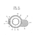
- FIG. 11 is a structural sectional view of a conventional steering angle sensor unit taken along line 11-11 in FIG. 12
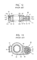
- FIG. 12 is a structural sectional view taken along line 12-12 in FIG. 11
- FIG. 13 is a structural sectional view taken along line 13-13 in FIG. 12.
- a steering angle sensor unit 80 comprises a rotor member 52 that is fixed to a steering shaft (not shown) of a vehicle and that turns with the operation of a steering wheel (not shown), a first casing 53 spaced around the rotor member 52 at a predetermined interval and having a smooth inner peripheral surface to serve as a stator member, a flexible cable 54 for forming a rotary connector, a winding core 56 fitted in or integrally formed with a second casing 55 having a smooth inner peripheral surface to wind the flexible cable 54 thereon, and the like.
- the first casing 53 and the second casing 55 are integrally formed, and the second casing 55 is spaced around the winding core 56 at a predetermined interval.
- a winding-assist member 57 that can turn coaxially with the winding core 56 is disposed between the second casing 55 and the winding core 56 at predetermined distances therefrom.
- a wall 58 is disposed between the first casing 53 and the second casing 55, and a cable path 59 is formed at the end of the wall 58.
- a steering angle sensor 70 contains a rotary connector 71.
- a photo-interrupter 61 is placed in the first casing 53 that does not move with the steering wheel being operated, and includes a photoreceptor 62 and a light emitting member 63 that sandwich the outer peripheral portion of the slit plate 60 and the through holes 60a.
- the photo-interrupter 61 also has a printed circuit board 64 for detecting signals that are output when the slit plate 60 blocks or passes the light travelling from the light emitting member 63 toward the photoreceptor 62.
- the rotor member 52 having the slit plate 60 fixed thereto is loosely fitted with a clearance in holes 53c and 53d formed through an upper wall 53a and a lower wall 53b of the first casing 53.
- the printed circuit board 64 is connected to both the photoreceptor 62 and the light emitting member 63, and is provided with a power supply circuit (not shown) for supplying electric power to the photoreceptor 62 and the light emitting member 63, and the like.
- One end of the flexible cable 54 is fixed to the rotor member 52 serving as a rotor in the steering angle sensor 70.
- the other end of the flexible cable 54 is wound on the winding core 56, fixed to the second casing 55, and electrically connected to an external output connector that is not shown.
- the rotor member 52 in the steering angle sensor unit 80 turns.
- the slit plate 60 also turns.
- light emitted from the light emitting member 63 in the photo-interrupter 61 is blocked by or passed through the through holes 60a of the slit plate 60 that turns between the light emitting member 63 and the photoreceptor 62.
- a detection signal (photocurrent) output from the photoreceptor 62 based on the light thus passed or blocked is output via an electric circuit formed on the printed circuit board 64.
- the turn angle of the steering shaft is calculated in a central processing unit (CPU), which is not shown, and the like.
- the turn angle of the steering shaft represents the steering amount or the steering angle of the steering wheel that is operated by a passenger in turning the vehicle.
- the turn state of the vehicle, the lateral acceleration of the vehicle body in the lateral direction, or the like is detected by using such calculated values, and this is used to control the vehicle in order to improve the stability of running of the vehicle or the riding comfort of the passenger, for example, to control the suspension.
- the flexible cable 54 for constituting the rotary connector 71 is wound around the rotor member 52 or rewound.
- This flexible cable 54 electrically connects an electric device on the side of the steering wheel and an electric device on the side of the vehicle body.
- the rotary connector generally comprises a pair of housings coupled so that they can relatively turn, and a flexible cable wound in an annular storage space defined between the housings. Both ends of the flexible cable are electrically led outside while they are fixed to the housings.
- One of the housings is used as a rotor member, and the other is used as a stator member. When the rotor member is turned in the forward or reverse direction, the flexible cable is wound up or rewound inside the storage space, depending on the turning direction.
- the rotary connector having such a structure is incorporated in a steering device of a motor vehicle, and used as a connecting means for electrically connecting a steering wheel and a column.
- a known mounting structure is widely adopted, in which a rotor member in a rotary connector is connected to a steering wheel and a stator member in the rotary connector is attached to a combination switch on the side of a column.
- This combination switch contains various switch units, such as a head-lamp switch and a wiper switch.
- the head-lamp switch is provided with an indicator cancel mechanism for causing a control lever at the right or left working position to automatically return to the center position.
- a cancel cam is formed at a part of the rotor member that projects from the bottom face of the stator member in the rotary connector, and a cancel lever in the indicator cancel mechanism is put into the turn area of the cancel cam, whereby the indicator cancel mechanism is operated by using the turning force of the rotor member.
- the cancel lever is driven by the cancel cam of the rotor member, and the control lever thereby automatically returns to the center position.
- the rotor member 52 to which the slit plate 60 is fixed, functions as both a rotor member in the steering angle sensor 70 and a rotor member in the rotary connector 71, and is loosely fitted with a clearance in the holes 53c and 53d that are formed through the upper wall 53a and the lower wall 53b of the first casing 53.
- the rotary connector 71 contains the flexible cable 54 and it does not stably turn when the flexible cable 54 is wound or rewound unless a predetermined clearance is ensured. Therefore, there is a need to provide some play between the rotor member and the stator member in the rotary connector 71.
- the rotation axis of the rotor member substantially deviates (offsets in the axial and radial directions). Since the slit plate 60 is fixed to the rotor member, the position of the slit passing between the photoreceptor 62 and the light emitting member 63 substantially changes, whereby the detection signal, obtained by the passage and block of light between the light emitting member 63 and the photoreceptor 62 with the turn of the slit plate 60, fluctuates and is not stable. In recent years, the steering angle sensor 70 has been required to have higher precision and higher resolution, and the adverse effect of the play is not negligible.
- stator member and the rotor member that are constituents of the rotary connector are not closely coupled to each other, and, in general, the rotor member is turnably coupled with some clearance with respect to a guide hole of the stator member so that this clearance absorbs the measuring errors and the mounting errors of the components. Therefore, there is a fear that the rotor member will turn within the clearance at an inclined angle with respect to the center axis of the stator member mounted on a casing of the combination switch. If the cancel cam is formed at the projecting portion of the rotor member, as in the related art mentioned above, the cancel cam and the cancel lever are prone to relative offset, thereby disabling the cancel lever.
- the present invention has been made to solve the problems of the related art, and has as an object the provision of a steering angle sensor unit formed by combining a rotary connector that needs a fixed play for smooth turn and a steering angle sensor that needs to limit the play for high precision and high resolution, without impairing the functions and performance thereof.
- a steering angle sensor unit including a rotary connector for electrically connecting an electric device mounted on a steering wheel and an electric device mounted on a vehicle body, and a steering angle sensor for detecting information about the turn of the steering wheel, wherein a rotor member in the rotary connector and a rotor member in the steering angle sensor are formed of separate members, one of the rotor member in the rotary connector and the rotor member in the steering angle sensor has a slot extending in the radial direction, the other rotor member has a projection having almost the same diameter as the minor diameter of the slot, and the slot and the projection are engaged with each other.
- a steering angle sensor unit including a rotary connector for electrically connecting an electric device mounted on a steering wheel and an electric device mounted on a vehicle body, and a steering angle sensor for detecting information about the turn of the steering wheel, wherein a rotor member in the rotary connector and a rotor member in the steering angle sensor are formed of separate members, the rotor member in the steering angle sensor has a slot extending in the radial direction, the rotor member in the rotary connector has a projection having almost the same diameter as the minor diameter of the slot, and the slot and the projection are engaged with each other.
- a coil spring is placed between the rotor member in the rotary connector and the rotor member in the steering angle sensor so that the resilient force of the coil spring resiliently urges both the rotor members in such a direction as to separate the rotor members.
- the rotor member in the rotary connector has a flexible engaging portion
- the rotor member in the steering angle sensor has a projection to be engaged with the flexible engaging portion
- the flexible engaging portion is engaged with the projection
- the flexible engaging portion and the slot extending in the radial direction that are formed in the rotor member of the rotary connector are located at positions spaced through an angle of 180° about the center axis of the rotor member.
- the steering angle sensor unit may include a plurality of flexible engaging portions.
- a steering angle sensor unit including a rotary connector for electrically connecting an electric device mounted on a steering wheel and an electric device mounted on a vehicle body, and a steering angle sensor for detecting information about the turn of the steering wheel, wherein a rotor member in the rotary connector and a rotor member in the steering angle sensor are formed of separate members, the rotor member in the rotary connector and the rotor member in the steering angle sensor have rotary engaging sections at which the rotor members are engaged with each other, a coil spring is placed between the rotor member in the rotary connector and the rotor member in the steering angle sensor, and the rotor members are resiliently urged by the resilient force of the coil spring in such a direction as to separate the rotor members.
- a steering angle sensor unit including a rotary connector for electrically connecting an electric device mounted on a steering wheel and an electric device mounted on a vehicle body, and a steering angle sensor for detecting information about the turn of the steering wheel, wherein stator members in the rotary connector and the steering angle sensor are combined with each other, rotor members in the rotary connector and the steering angle sensor are engaged via a play absorbing portion that permits the relative shift thereof in the radial direction, and the rotor member in the steering angle sensor has a cancel cam for operating an indicator cancel mechanism.
- the indicator cancel mechanism can be reliably operated by the cancel cam formed in the rotor member of the steering angle sensor.
- FIG. 1 is an exploded perspective view of a steering angle sensor unit according to a first embodiment of the present invention.
- the steering angle sensor unit comprises a rotary connector 200 and a steering angle sensor 210 that are made in elastic contact with each other by a coil spring 16.
- the rotary connector 200 generally comprises a pair of rotor members, an upper rotor member 1 and a lower rotor member 2, that are concentrically and turnably connected with respect to each other, a cable holder 5, a lower cover 6, and a flexible cable 9 that is held and wound in a space formed between the upper and lower rotor members 1 and 2, the cable holder 5, and the lower cover 6. Both ends of the flexible cable 9 are indirectly electrically led out of the cable holder 5 via an inner lead block 12 and an outer lead block 13. In this case, the inner lead block 12 is retained by the outer peripheral portion of the upper rotor member 1, and the outer lead block 13 is retained by the outer peripheral portion of the lower cover 6.
- the upper rotor member 1 and the lower rotor member 2 are used as a movable housing, and the combination of the cable holder 5 and the lower cover 6 is used as a fixed housing.
- the movable housing is turned clockwise or counterclockwise, the flexible cable 9 is wound or rewound inside the space.
- the upper and lower rotor members 1 and 2 serving as the movable housing and the cable holder 5 and the lower cover 6 serving as the fixed housing are relatively loosely engaged with each other.
- a relatively large clearance is formed in the engaged portion therebetween. The play between the movable housing and the fixed housing because of the clearance in the engaged portion keeps the turn of the rotary connector 200 stable.
- the fixed housing including the cable holder 5 and the lower cover 6 is fixed to a vehicle body
- the movable housing including the upper rotor member 1 and the lower rotor member 2 is fixed to a hub (not shown) of a steering shaft.
- Both ends of the flexible cable 9 are connected to electric devices in the vehicle body and a steering wheel via connectors 14 and 15, respectively.
- the rotary connector 200 is used as electrical connecting means for an automobile-installed air bag system, a horn circuit, and the like.
- FIG. 1 shows the steering angle sensor 210 in an inverted position.
- the steering angle sensor 210 generally comprises a pair of covers, an upper cover 7 and a lower cover 8, that are concentrically connected to each other, a first rotor member 3 and a second rotor member 4 that are turnably connected to the upper cover 7 and the lower cover 8, and a code plate 10 and a photo-interrupter 11 that are held in the space formed between the upper and lower covers 7 and 8 and the first and second rotor members 3 and 4.
- the photo-interrupter 11 is disposed so that it crosses over a through hole on the code plate 10.
- the code plate 10 and the photo-interrupter 11 constitute, for example, an absolute encoder that precisely detects the turn angle and the like based on the turn of the code plate 10.
- This code plate 10 is sandwiched and held between the first rotor member 3 and the second rotor member 4, and turns along therewith.
- a fixed housing including the upper cover 7 and the lower cover 8 is fixed to the fixed housing of the rotary connector 200, and a movable housing including the first rotor member 3 and the second rotor member 4 is engaged with the movable housing of the rotary connector 200.
- the photo-interrupter 11 outputs a detection signal.
- the clearance between the first and second rotor members 3 and 4 serving as the movable housing and the upper cover 7 and the lower cover 8 serving as the fixed housing in the steering angle sensor 210 is kept smaller and more precise than that of the rotary connector 200. This stabilizes the position of the code plate 10 with respect to the photo-interrupter 11 that is located in a direction intersecting the center axis of the rotor member (radial direction).
- the upper cover 7 and the lower cover 8 serving as the fixed housing in the steering angle sensor 210 and the cable holder 5 and the lower cover 6 serving as the fixed housing in the rotary connector 200 are combined into one by screws or the like, and the fixed housing in the rotary connector 200 is fixed to the vehicle body.
- the first and second rotor members 3 and 4 serving as the movable housing in the steering angle sensor 210 and the upper and lower rotor members 1 and 2 serving as the movable housing in the rotary connector 200 are engaged with each other, and the upper rotor member 1 in the rotary connector 1 is fixed to the hub of the steering shaft.
- FIGS. 2, 3, and 4 are plan, side, and bottom views of the lower rotor member 2 in the rotary connector 200, respectively.
- the lower rotor member 2 of the rotary connector 200 is made of a molding material, and almost shaped like a ring.
- the lower rotor member 2 includes a cylindrical portion 2b having a circular center hole 2a at the center thereof, and a circular flange portion 2c projecting out toward the periphery from the center of the cylindrical portion 2b.
- the cylindrical portion 2b has at the upper end a pair of notches 2h that are almost shaped like a pen tip and opposed to each other across the center axis of the cylindrical portion 2b, and a pair of cutouts 2i that are shifted from the notches 2h through an angle of 90°.
- the flange portion 2c has at a predetermined position thereon a slot 2d for forming a rotary engaging section that is almost elliptically shaped, has parallel long sides, and extends in the radial direction.
- the flange portion 2c also has a rectangular hole 2e for forming a rotary engaging section that is formed at a position shifted from the slot 2d through an angle of 180° about the center axis of the center hole 2a.
- a pair of retaining pieces 2f are formed in the shape of a fork projecting inwardly in parallel from one side of the hole 2e that is closer to the center hole 2a, and the retaining pieces 2f have elasticity in the circumferential direction of the flange portion 2c.
- the hole 2e and the retaining pieces 2f and 2f constitute a flexible engaging portion 2g that forms the rotary engaging section.
- the steering shaft (not shown) penetrates.
- FIGS. 5, 6, and 7 are plan, side, and cross-sectional views of the first rotor member 3 in the steering angle sensor 210, respectively.
- the first rotor member 3 in the steering angle sensor 210 is formed by molding a molding material in about the shape of a ring, and comprises an inner cylindrical portion 3b having a circular center hole 3a at the center thereof, an outer cylindrical portion 3d, and a flange portion 3e formed around the upper end of the outer cylindrical portion 3d.
- the inner cylindrical portion 3b and the outer cylindrical portion 3d are connected at the lower ends, and thereby combined into one.
- first cylindrical projection 3i that has a circular hole 3h at the center and projects upward to form the rotary engaging section
- second cylindrical projection 3j that is located symmetrically about the center axis of the center hole 3a with respect to the first projection 3i to form the rotary engaging section.
- third cylindrical projections 3k and 3m projecting outward are symmetrically positioned about the center axis of the center hole 3a.
- arc-shaped recesses 3c are formed, and a plurality of (e.g., three) connecting portions 3n are also formed.
- the connecting portions 3n have threaded holes 3p. Through the center hole 3a, the steering shaft (not shown) penetrates.
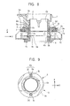
- FIG. 8 is a cross-sectional view showing the principal part of an engaged state of the lower rotor member 2 in the rotary connector 200 and the first rotor member 3 in the steering angle sensor 210 in the embodiment of the present invention
- FIG. 9 is an explanatory view showing the engaged state shown in FIG. 8.
- the fixed housing is formed by retaining the lower cover 6 with the cable holder 5 containing the flexible cable 9, the cylindrical portion 2b of the lower rotor member 2 is inserted through the hole 1b of the upper rotor member 1 so that the flange portion 1a of the upper rotor member 1 faces up and the flange portion 2c of the lower rotor member 2 faces down, and the upper rotor member 1 and the lower rotor member 2 are combined with the fixed housing by snapping together.
- the fixed housing is assembled by retaining the upper cover 7 and the lower cover 8 having the photo-interrupter 11 and the code plate 10 therebetween, and then, the third projections 3k and 3m formed on the lower surface of the first rotor member 3 are engaged with recesses 4b and 4c formed on the upper surface of the second rotor member 4 while the code plate 10 is engaged with the third projections 3k and 3m so that the flange portion 3e of the first rotor member 3 faces up and the flange portion 4a of the second rotor member 4 faces down. Then, the first rotor member 3 and the second rotor member 4 are combined as the movable housing by screws (not shown) while holding the code plate 10 therebetween.
- the coil spring 16 is placed between the outer wall of the cylindrical portion 2b of the lower rotor member 2 in the rotary connector 200 and the inner wall of the outer cylindrical portion 3d of the first rotor member 3 in the steering angle sensor 210, and the cable holder 5 in the rotary connector 200 and the upper cover 7 in the steering angle sensor 210 are combined by screws (not shown), whereby the steering angle sensor unit is assembled. In this state, the coil spring 16 is placed so as to lie on the upper faces of the connecting portions 3n in the first rotor member 3.
- the first rotor member 3 and the lower rotor member 2 are resiliently urged by the resilient force of the coil spring 16 in such a direction that they separate from each other.
- This resilient urging causes the lower side of the flange portion 3e of the first rotor member 3 in the steering angle sensor 210 to be always in contact with the upper side of an upper wall 7a of the upper cover 7.
- the first projection 3i and the second projection 3j which are formed on the flange portion 3e in the first rotor member 3 to constitute the rotary engaging sections, project toward the flange portion 2c of the lower rotor member 2.
- the first projection 3i is located inside the slot 2d that constitutes the rotary engaging section of the lower rotor member 2
- the second projection 3j is located between the pair of retaining pieces 2f and 2f that form the flexible engaging portion 2g serving as the rotary engaging section.
- the minor diameter of the slot 2d is almost equal to the diameter of the first projection 3i, and the engagement therebetween forms a minute clearance (e.g., a clearance of about 50 ⁇ m).
- the major diameter of the slot 2d is larger than the diameter of the first projection 3i. Therefore, the first projection 3i is allowed to move in the direction of the major diameter of the slot 2d.
- the second projection 3j is in elastic contact with the retaining pieces 2f having elasticity inside the hole 2e, and is movable within the hole 2e in a similar manner to the first projection 3i.
- the lower rotor member 2 of the rotary connector 200 has such a structure as to allow offset (play) in the direction intersecting the center axis after being coupled with the high-precision steering angle sensor 210.
- the play of the lower rotor member 2 in the X-Y direction is allowed by the movement of the first projection 3i of the first rotor member 3 in the direction of the major diameter of the slot 2d, and the play in the Z direction (the direction of the center axis) is allowed by the resilient force of the coil spring 16 because the coil spring 16 is interposed between the lower rotor member 2 and the first rotor member 3.
- both ends of the coil spring 16 may be fixedly caught by retaining portions (e.g., retaining holes) that are formed in the lower rotor member 2 and the first rotor member 3, respectively.
- the turn of the first rotor member 3 is precisely transmitted because the first projection 3i of the first rotor member 3 is engaged with the slot 2d of the lower rotor member 2 with little clearance therebetween.
- the first rotor member 3 does not move in the direction of the center axis (the axial direction) because of the resilient force of the coil spring 16, and the lower surface of the flange portion 3e thereof is always in contact with the upper surface of the upper wall 7a of the upper cover 7. Since the length between the flange portion 3e and the code plate 10 is precisely defined, the length between the upper wall 7a and the code plate 10 is always kept constant. Therefore, the positions of the photo-interrupter 11 and the code plate 10 formed in the upper cover 7, namely, the position of the code plate 10 in the gap of the photo-interrupter 11 in the axial direction, is made fixed, and a stable encoder output signal can be obtained.
- the lower rotor member 2 has the flexible engaging portion 2g besides the slot 2d. Since the outer peripheral surface of the second projection 3j of the first rotor member 3 that is engaged with the flexible engaging portion 2g is in contact with one of the retaining pieces 2f that form the flexible engaging portion 2g, the force of the contact also permits a constant turning force to be transmitted.
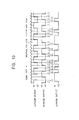
- FIG. 10 is a waveform chart showing detection signals output from the absolute encoder in the steering angle sensor 210.
- the absolute encoder detects A-phase, B-phase, and Z-phase output signals, and calculates the turn angle and the like.
- the absolute encoder calculates the turn direction (clockwise or counterclockwise) and the turn angle of the steering shaft by detecting the rising waveform and the falling waveform of the A-phase signal and the rising waveform and the falling waveform of the B-phase signal.
- the absolute encoder reads the rising and falling positions of the Z-phase signal as codes based on the rise and fall of the A-phase and B-phase signals, or counts the width thereof, and calculates the turn angle from the reference position according to an arithmetic table stored in a central processing unit (CPU).
- CPU central processing unit
- the rising positions and the falling positions of the waves of the phases always vary due to optical, electrical and mechanical factors.
- the output phase difference between the rising or falling position of the Z-phase signal and the rising or falling position of the A-phase or B-phase signal is taken as a mechanical angle ⁇ , when the value ⁇ , namely, the resolution, is 1.5° and there are no variations, all the mechanical angles ⁇ are 0 .75°.
- ⁇ namely, the resolution
- the lower rotor member 2 in the rotary connector 200 since the lower rotor member 2 in the rotary connector 200 has the slot 2c and the flexible engaging portion 2g, it is engaged with the first rotor member 3 in the steering angle sensor 210 at two points. This makes it possible to smoothly transmit the turn, to reduce the variations in the aforementioned angle ⁇ , and to thereby obtain a more stable and more precise output signal.
- the lower rotor member 2 in the rotary connector 200 has one flexible engaging portion 2g in the first embodiment of the present invention, it may be possible to form a plurality of flexible engaging portions 2g in the lower rotor member 2 and to form a plurality of projections in the first rotor member 3 of the steering angle sensor 210 corresponding to this plurality of flexible engaging portions 2g.
- the rotary engaging section in which the lower rotor member 2 has the slot 2d and the flexible engaging portion 2g and the first rotor member 3 has two projections, has been described in the first embodiment of the present invention, it is not limited to the above-described structure.
- the lower rotor member 2 may have two projections and the first rotor member 3 may have the slot 2d and the flexible engaging portion 2g.
- two flexible engaging portions 2g may be formed without forming the slot 2d.
- a steering angle sensor unit includes a rotary connector for electrically connecting an electrical component mounted on a steering wheel to a vehicle body, and a steering angle sensor for detecting information about the turn of the steering wheel, wherein stator members in the rotary connector and the steering angle sensor are fixed and combined with each other, rotor members in the rotary connector and the steering angle sensor are engaged via a play absorbing portion that permits the relative shift thereof in the radial direction, and the rotor member in the steering angle sensor has a cancel cam for operating an indicator cancel mechanism.
- one of the rotor members in the rotary connector and the steering angle sensor has a slot extending in the radial direction, and the other rotor member has a projection that is slidable inside the slot.
- FIG. 14 is a plan view showing a state in which a steering angle sensor unit of the second embodiment is attached to a combination switch
- FIG. 15 is an exploded perspective view of the steering angle sensor unit
- FIG. 16 is a bottom view of a lower rotor in a rotary connector of the steering angle sensor unit
- FIG. 17 is a plan view of an upper rotor in a steering angle sensor of the steering angle sensor
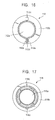
- FIG. 18 is a plan view showing a state in which the lower rotor in the rotary connector and the upper rotor in the steering angle sensor are coupled to each other
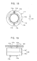
- FIG. 19 is an explanatory view showing a state in which the steering angle sensor unit and a steering wheel are connected to each other.
- a steering angle sensor unit 101 comprises a rotary connector 102 and a steering angle sensor 103 that are combined into one.
- This steering angle sensor unit 101 is to be incorporated as one unit component between a steering wheel and a combination switch on the side of a column.
- the combination switch has a casing 104 serving as an outer shell.
- the casing 104 has a plurality of supporting columns 104a, an insertion hole 105, and holder sections 106 opposing across the insertion hole 105 on the right and left sides thereof.
- a base 107a of a head-lamp switch 107 is fixed to one of the holder sections 106, and a control lever 108 for performing a right-and-left indication and an indication for passing is supported by the base 107a.
- the base 107a contains known mechanisms, such as a lock mechanism for locking the control lever 108 in the working position, an indicator cancel mechanism for causing the control lever 108 in the working position to automatically return to the center position.
- the leading end of a cancel lever 107b which is a constituent of the indicator canceling mechanism, projects into the insertion hole 105.
- a wiper switch is mounted on the other holder section 106.
- the rotary connector 102 comprises a cable holder 109 and a lower cover 110 that combined into a first stator member, and an upper rotor 111 and a lower rotor 112 that are combined into a first rotor member.
- a flat cable 113 is wound, for example, in a spiral form in an annular space defined between the first stator member (the cable holder 109 and the lower cover 110) and the first rotor member (the upper rotor 111 and the lower rotor 112). Both ends of the flat cable 113 are electrically led out of the stator member including the cable holder 109 and the like via an inner lead block 114 and an outer lead block 115.
- the inner lead block 114 is retained by the outer peripheral portion of the upper rotor 111, and the outer lead block 115 is retained by the outer peripheral portion of the lower cover 110.
- the upper rotor 111 has a pair of finger portions 111a that project outside from the top face of the cable holder 109.
- the upper rotor 111 and the lower rotor 112, and the cable holder 109 and the lower cover 110 are turnably coupled with a relatively large clearance.
- the play between the first rotor member and the first stator member because of the clearance keeps the turn of the rotary connector 102 stable.
- the steering angle sensor 103 which is shown in an inverted position in FIG. 15, comprises an upper cover 116 and a lower cover 117 that are combined into a second stator member, and an upper rotor 118 and a lower rotor 119 that are combined into a second rotor member.
- a code plate 120 is fixedly held between the upper rotor 118 and the lower rotor 119.
- the lower rotor 119 has a cylindrical member 119a that projects outside from the bottom face of the lower cover 117. Formed in a part of the cylindrical member 119a is a cancel cam 119b for operating the cancel lever 107b in the aforementioned indicator cancel mechanism.
- a photo-interrupter 121 is disposed in an annular space defined between the second stator member (the upper cover 116 and the lower cover 117) and the second rotor member (the upper rotor 118 and the lower rotor 119) so that it crosses over through holes of the code plate 120.
- the code plate 120 and the photo-interrupter 121 constitute, for example, an absolute encoder.
- the code plate 120 turns along with the upper and lower rotors 118 and 119, and an output signal regarding information about the turn of the code plate 120 is detected from the photo-interrupter 121.
- the clearance between the upper rotor 118 and the lower rotor 119, and the upper cover 116 and the lower cover 117 is set smaller more precisely than in the rotary connector 102, which stabilizes the position of the code plate 120 with respect to the photo-interrupter 121 that lies in a direction intersecting the center axis of the second rotor member (radial direction).
- the lower rotor 112 in the rotary connector 102 has a center hole 112a at the center thereof, and a ring-shaped flange portion 112b formed around the center hole 112a.
- the flange portion 112b has a slot 112c and a rectangular hole 112d disposed at opposing positions that are spaced through an angle of 180° about the center of the center hole 112a.
- the slot 112c is almost elliptically shaped, and is provided with parallel long sides extending in the radial direction.
- the rectangular hole 112 also extends in the radial direction, and is provided with elastic pieces 112e on both sides thereof.
- the upper rotor 118 in the steering angle sensor 103 has a center hole 118a at the center thereof, and a ring-shaped flange portion 118b formed around the center hole 118a.
- the flange portion 118b has a first cylindrical projection 118c and a second cylindrical projection 118d placed at opposing positions that are spaced through an angle of 180° about the center of the center hole 118a.
- the rotary connector 102 and the steering angle sensor 103 thus structured are combined and assembled as the steering angle sensor unit 101 as follows. That is, the cable holder 109 in the rotary connector 102 and the upper cover 116 in the steering angle sensor 103 are fixed by screws, which are not shown, in a state in which a coil spring 122 is interposed between the lower rotor 112 in the rotary connector 102 and the upper rotor 118 in the steering angle sensor 103, whereby the first stator member in the rotary connector 102 and the second stator member in the steering angle sensor 103 are fixed and combined with each other.
- the resilient urging causes the lower surface of the flange portion 118b of the upper rotor 118 to be always in contact with the top face of the upper cover 116.
- the first projection 118c and the second projection 118d of the upper rotor 118 are inserted in the slot 112c and the rectangular hole 112d of the lower rotor 112, respectively, as shown in FIG.
- the rotor member (the lower rotor 112) in the rotary connector 102 and the rotor member (the upper rotor 118) in the steering angle sensor 103 are coupled via two play absorbing portions that are formed of the engaged portion between the slot 112c and the first projection 118c and the engaged portion between the rectangular hole 112d and the second projection 118d.
- the minor diameter of the slot 112c and the diameter of the first projection 118c are almost equally set so that the slot 112c and the first projection 118c are engaged with a minute clearance (e.g., 50 ⁇ m). Since the major diameter of the slot 112c is set adequately larger than the diameter of the first projection 118c, the first projection 118c is allowed to move in the direction of the major diameter of the slot 112c. Similarly, the rectangular hole 112d and the second projection 118d are engaged with little clearance, and the major diameter of the rectangular hole 112d is set adequately larger than the diameter of the second projection 118d. Therefore, the second projection 118d is also allowed to move in the direction of the major diameter of the rectangular hole 112d.
- a minute clearance e.g. 50 ⁇ m
- the lower rotor 112 in the rotary connector 102 has such a structure as to allow the play in a direction intersecting the center axis (in the X-Y directions in FIG. 18) after being coupled to the high-precision steering angle sensor 103.
- the play in the direction of the center axis is allowed by the resilient force of the coil spring 122.
- the steering angle sensor unit 101 thus assembled is incorporated for use between the steering wheel and the combination switch on the side of the column, as mentioned above.
- the steering angle sensor unit 101 is laid on the casing 104 of the combination switch fixed to a column cover or the like, and the first and second stator members in the rotary connector 102 and the steering angle sensor 103, which has been combined into one, are screwed to the supporting columns 104b of the casing 104, as shown in FIG. 14.
- the cylindrical member 119a of the lower rotor 119 in the steering angle sensor 103 is inserted in the insertion hole 105 of the casing 104, and the cancel cam 119b formed on the cylindrical member 119a faces the leading end of the cancel lever 107b inside the insertion hole 105. Therefore, the relative position between the cancel cam 119b formed in the lower rotor 119 in the high-precision steering angle sensor 103, in which there is little clearance at the rotary engaging section, and the cancel lever 107b of the combination switch is precisely maintained.
- a steering wheel 123 is fixed to a steering shaft that is not shown, and the finger portions 111a formed on the upper rotor 111 in the rotary connector 102 are inserted in and caught by retaining holes 123a that are formed at predetermined positions of the steering wheel 123.
- both ends of the flat cable 113 are connected to the steering wheel 123 and the combination switch via connectors 124 and 125, respectively.
- electrical components mounted on the steering wheel 123 such as an air bag inflator, are connected to the combination switch via the flat cable 113 in the rotary connector 102.
- the lower rotor 112 in the rotary connector 102 has such a structure as to allow the play in the direction intersecting the center axis, the turn of the lower rotor 112 can be transmitted to the upper rotor 118 in the steering angle sensor 103 in which there is little clearance at the rotary engaging section. Furthermore, since the lower rotor 112 does not move in the direction of the center axis (the axial direction) because of the resilient force of the coil spring 122, the positions of the photo-interrupter 21 and the code plate 120 formed in the upper cover 116, namely, the operation gap, is fixed, which makes it possible to obtain a stable encoder output signal.
- the cancel cam 119b formed on the lower rotor 119 in the second rotor member turns inside the insertion hole 105. Therefore, when the steering wheel 123 is turned to the neutral position, the cancel cam 119b drives the cancel lever 107b, and the control lever 108 at the working position thereby automatically returns to the center position.
- the lower rotor 112 in the rotary connector 102 has such a structure as to allow the play in the direction intersecting the center axis thereof, the turn of the lower rotor 112 can be transmitted to the upper rotor 118 in the steering angle sensor 103 in which there is little clearance at the rotary engaging section, and the cancel lever 107b can be reliably operated by the cancel cam 119b of the lower rotor 119 that turns along with the upper rotor 118 in the steering angle sensor 103.
- the steering angle sensor may be disposed on the side of the steering wheel, and the rotary connector may be disposed under the steering angle sensor.
- the steering angle sensor since the steering angle sensor is directly turnediby the rotary connector, it can more precisely detect the steering angle of the steering wheel.
- the rotor member in the rotary connector and the rotor member in the steering angle sensor are formed of separate members, one of the rotor members in the rotary connector and the steering angle sensor has a slot extending in the radial direction, the other rotor member has a projection having almost the same diameter as the minor diameter of the slot, and the slot and the projection are engaged with each other.
- the coil spring is located between the rotor member in the rotary connector and the rotor member in the steering angle sensor, and both the rotor members are resiliently urged by the resilient force of the coil spring in such a direction as to separate the rotor members. Therefore, the flange portion of the rotor member in the steering angle sensor is always in contact with the upper wall of the upper cover, and the code plate fixed to the rotor member is always urged in the direction of the center axis. Thereby, the code plate and the photo-interrupter fixed to the fixed housing are located in a mutual stable relationship, which makes it possible to stabilize a detection signal from the photo-interrupter and to thereby provide a high-precision steering angle sensor unit.
- the rotor member in the rotary connector has a flexible engaging portion
- the rotor member in the steering angle sensor has a projection to be engaged with the flexible engaging portion
- the flexible engaging portion is engaged with the projection. Since the projections of the rotor member in the steering angle sensor are engaged at two points, with the flexible engaging portion and the slot, the turn of the rotor member in the rotary connector is more reliably transmitted to the rotor member in the steering angle sensor, which makes the turn more smooth.
- the turn of the rotor member in the rotary connector can be even more reliably transmitted to the rotor member in the steering angle sensor.
- the flexible engaging portion and the slot extending in the radial direction are formed on the flange portion of the rotor member in the rotary connector at positions spaced through an angle of 180° about the center axis of the rotor member, it is possible to provide a steering angle sensor unit that is able to most stably transmit the turn of the rotor member in the rotary connector to the rotor member in the steering angle sensor.
- the steering angle sensor for detecting information about the turn of the steering wheel is combined with the rotary connector, the rotor members in the steering angle sensor and the rotary connector are engaged via the play absorbing portion that permits the relative shift therebetween in the radial direction, and the rotor member in the steering angle sensor has the cancel cam for operating the indicator cancel mechanism. Since the relative offset between the rotor members in the rotary connector and the steering angle sensor in the radial direction is absorbed, it is possible to set a sufficiently small clearance between the stator member and the rotor member in the steering angle sensor while a required clearance is ensured between the stator member and the rotor member in the rotary connector, and to cause the cancel cam formed on the rotor member in the steering angle sensor to reliably operate the indicator cancel mechanism.
Abstract
Description
- The present invention relates to a steering angle sensor unit mounted on a steering shaft of a motor vehicle and the like to detect information about the turn of a steering wheel and to electrically connect electric devices mounted on the steering wheel and a vehicle body.
- Hitherto, a device called a steering angle sensor unit has been proposed which includes a combination of a steering angle sensor for detecting information about the turn of a steering wheel and a rotary connector for electrically connecting an electric device mounted on the steering wheel and an electric device mounted on a vehicle body.
- A steering angle sensor detects the steering angle and the steering direction of the steering wheel, and uses these to control the damping force of the suspension, the shift position of the automatic transmission, and the steering of the rear wheels of a four-wheel steering (4WS) vehicle. In general, the steering angle sensor comprises a code plate mounted on a rotor section that is rotationally driven by the steering wheel, and a light emitting device and a photoreceptor mounted inside a casing for forming a stator section. On the other hand, a rotary connector permits the electrical connection between an electric device mounted on the steering wheel serving as a rotary member, and an electric device mounted on a vehicle body serving as a fixed member. In some rotary connectors, a flexible electric cable or optical fiber cable (hereinafter generically referred to as "flexible cable") is wound and held between a rotor section to be rotationally driven by the steering wheel and a casing for forming a stator section, the flexible cable being fixed to the rotor section at one end and to the stator section at the other end, and the electrical connection between the electric devices is permitted by winding and rewinding the flexible cable.
- A conventional steering angle sensor unit will now be described.
- FIG. 11 is a structural sectional view of a conventional steering angle sensor unit taken along line 11-11 in FIG. 12, FIG. 12 is a structural sectional view taken along line 12-12 in FIG. 11, and FIG. 13 is a structural sectional view taken along line 13-13 in FIG. 12.
- As shown in FIGS. 11 to 13, a steering
angle sensor unit 80 comprises arotor member 52 that is fixed to a steering shaft (not shown) of a vehicle and that turns with the operation of a steering wheel (not shown), afirst casing 53 spaced around therotor member 52 at a predetermined interval and having a smooth inner peripheral surface to serve as a stator member, aflexible cable 54 for forming a rotary connector, a windingcore 56 fitted in or integrally formed with asecond casing 55 having a smooth inner peripheral surface to wind theflexible cable 54 thereon, and the like. - The
first casing 53 and thesecond casing 55 are integrally formed, and thesecond casing 55 is spaced around the windingcore 56 at a predetermined interval. A winding-assist member 57 that can turn coaxially with the windingcore 56 is disposed between thesecond casing 55 and the windingcore 56 at predetermined distances therefrom. Awall 58 is disposed between thefirst casing 53 and thesecond casing 55, and acable path 59 is formed at the end of thewall 58. - In the steering
angle sensor unit 80 having such a configuration, asteering angle sensor 70 contains arotary connector 71. - A description will now be given of the structure and placement of the
steering angle sensor 70 in the steeringangle sensor unit 80. - Fixed to the
rotor member 52 is aslit plate 60 having throughholes 60a that are spaced at predetermined intervals in the circumferential direction. A photo-interrupter 61 is placed in thefirst casing 53 that does not move with the steering wheel being operated, and includes aphotoreceptor 62 and alight emitting member 63 that sandwich the outer peripheral portion of theslit plate 60 and the throughholes 60a. The photo-interrupter 61 also has a printedcircuit board 64 for detecting signals that are output when theslit plate 60 blocks or passes the light travelling from thelight emitting member 63 toward thephotoreceptor 62. - The
rotor member 52 having theslit plate 60 fixed thereto is loosely fitted with a clearance inholes upper wall 53a and alower wall 53b of thefirst casing 53. The printedcircuit board 64 is connected to both thephotoreceptor 62 and thelight emitting member 63, and is provided with a power supply circuit (not shown) for supplying electric power to thephotoreceptor 62 and thelight emitting member 63, and the like. - The structure of the
rotary connector 71 will be next described. - One end of the
flexible cable 54 is fixed to therotor member 52 serving as a rotor in thesteering angle sensor 70. The other end of theflexible cable 54 is wound on the windingcore 56, fixed to thesecond casing 55, and electrically connected to an external output connector that is not shown. - Next, a description will be given of the operation of the steering
angle sensor unit 80 having the configuration mentioned above. - First, when the steering wheel (not shown) is operated, the
rotor member 52 in the steeringangle sensor unit 80 turns. Thereby, theslit plate 60 also turns. With the turn of theslit plate 60, light emitted from thelight emitting member 63 in the photo-interrupter 61 is blocked by or passed through the throughholes 60a of theslit plate 60 that turns between thelight emitting member 63 and thephotoreceptor 62. A detection signal (photocurrent) output from thephotoreceptor 62 based on the light thus passed or blocked is output via an electric circuit formed on the printedcircuit board 64. - Based on this output signal, the turn angle of the steering shaft is calculated in a central processing unit (CPU), which is not shown, and the like. The turn angle of the steering shaft represents the steering amount or the steering angle of the steering wheel that is operated by a passenger in turning the vehicle. The turn state of the vehicle, the lateral acceleration of the vehicle body in the lateral direction, or the like is detected by using such calculated values, and this is used to control the vehicle in order to improve the stability of running of the vehicle or the riding comfort of the passenger, for example, to control the suspension.
- When the
rotor member 52 turns, theflexible cable 54 for constituting therotary connector 71 is wound around therotor member 52 or rewound. Thisflexible cable 54 electrically connects an electric device on the side of the steering wheel and an electric device on the side of the vehicle body. - The rotary connector generally comprises a pair of housings coupled so that they can relatively turn, and a flexible cable wound in an annular storage space defined between the housings. Both ends of the flexible cable are electrically led outside while they are fixed to the housings. One of the housings is used as a rotor member, and the other is used as a stator member. When the rotor member is turned in the forward or reverse direction, the flexible cable is wound up or rewound inside the storage space, depending on the turning direction.
- The rotary connector having such a structure is incorporated in a steering device of a motor vehicle, and used as a connecting means for electrically connecting a steering wheel and a column. In this case, a known mounting structure is widely adopted, in which a rotor member in a rotary connector is connected to a steering wheel and a stator member in the rotary connector is attached to a combination switch on the side of a column. This combination switch contains various switch units, such as a head-lamp switch and a wiper switch. In general, the head-lamp switch is provided with an indicator cancel mechanism for causing a control lever at the right or left working position to automatically return to the center position.
- In a well-known manner, a cancel cam is formed at a part of the rotor member that projects from the bottom face of the stator member in the rotary connector, and a cancel lever in the indicator cancel mechanism is put into the turn area of the cancel cam, whereby the indicator cancel mechanism is operated by using the turning force of the rotor member. In this case, when the steering wheel is turned to the neutral position, since the rotor member in the rotary connector turns along with the steering wheel, the cancel lever is driven by the cancel cam of the rotor member, and the control lever thereby automatically returns to the center position.
- In the steering angle sensor unit having the configuration mentioned above, however, the
rotor member 52, to which theslit plate 60 is fixed, functions as both a rotor member in thesteering angle sensor 70 and a rotor member in therotary connector 71, and is loosely fitted with a clearance in theholes upper wall 53a and thelower wall 53b of thefirst casing 53. This is because therotary connector 71 contains theflexible cable 54 and it does not stably turn when theflexible cable 54 is wound or rewound unless a predetermined clearance is ensured. Therefore, there is a need to provide some play between the rotor member and the stator member in therotary connector 71. On the other hand, if there is a large clearance between the rotor member and the stator member in thesteering angle sensor 70, the rotation axis of the rotor member substantially deviates (offsets in the axial and radial directions). Since theslit plate 60 is fixed to the rotor member, the position of the slit passing between thephotoreceptor 62 and thelight emitting member 63 substantially changes, whereby the detection signal, obtained by the passage and block of light between thelight emitting member 63 and thephotoreceptor 62 with the turn of theslit plate 60, fluctuates and is not stable. In recent years, thesteering angle sensor 70 has been required to have higher precision and higher resolution, and the adverse effect of the play is not negligible. - Furthermore, the stator member and the rotor member that are constituents of the rotary connector are not closely coupled to each other, and, in general, the rotor member is turnably coupled with some clearance with respect to a guide hole of the stator member so that this clearance absorbs the measuring errors and the mounting errors of the components. Therefore, there is a fear that the rotor member will turn within the clearance at an inclined angle with respect to the center axis of the stator member mounted on a casing of the combination switch. If the cancel cam is formed at the projecting portion of the rotor member, as in the related art mentioned above, the cancel cam and the cancel lever are prone to relative offset, thereby disabling the cancel lever.
- The present invention has been made to solve the problems of the related art, and has as an object the provision of a steering angle sensor unit formed by combining a rotary connector that needs a fixed play for smooth turn and a steering angle sensor that needs to limit the play for high precision and high resolution, without impairing the functions and performance thereof.
- According to an aspect of the present invention, there is provided a steering angle sensor unit including a rotary connector for electrically connecting an electric device mounted on a steering wheel and an electric device mounted on a vehicle body, and a steering angle sensor for detecting information about the turn of the steering wheel, wherein a rotor member in the rotary connector and a rotor member in the steering angle sensor are formed of separate members, one of the rotor member in the rotary connector and the rotor member in the steering angle sensor has a slot extending in the radial direction, the other rotor member has a projection having almost the same diameter as the minor diameter of the slot, and the slot and the projection are engaged with each other.
- According to another aspect of the present invention, there is provided a steering angle sensor unit including a rotary connector for electrically connecting an electric device mounted on a steering wheel and an electric device mounted on a vehicle body, and a steering angle sensor for detecting information about the turn of the steering wheel, wherein a rotor member in the rotary connector and a rotor member in the steering angle sensor are formed of separate members, the rotor member in the steering angle sensor has a slot extending in the radial direction, the rotor member in the rotary connector has a projection having almost the same diameter as the minor diameter of the slot, and the slot and the projection are engaged with each other.
- Preferably, a coil spring is placed between the rotor member in the rotary connector and the rotor member in the steering angle sensor so that the resilient force of the coil spring resiliently urges both the rotor members in such a direction as to separate the rotor members.
- Preferably, the rotor member in the rotary connector has a flexible engaging portion, the rotor member in the steering angle sensor has a projection to be engaged with the flexible engaging portion, and the flexible engaging portion is engaged with the projection.
- Preferably, the flexible engaging portion and the slot extending in the radial direction that are formed in the rotor member of the rotary connector are located at positions spaced through an angle of 180° about the center axis of the rotor member.
- The steering angle sensor unit may include a plurality of flexible engaging portions.
- According to a further aspect of the present invention, there is provided a steering angle sensor unit including a rotary connector for electrically connecting an electric device mounted on a steering wheel and an electric device mounted on a vehicle body, and a steering angle sensor for detecting information about the turn of the steering wheel, wherein a rotor member in the rotary connector and a rotor member in the steering angle sensor are formed of separate members, the rotor member in the rotary connector and the rotor member in the steering angle sensor have rotary engaging sections at which the rotor members are engaged with each other, a coil spring is placed between the rotor member in the rotary connector and the rotor member in the steering angle sensor, and the rotor members are resiliently urged by the resilient force of the coil spring in such a direction as to separate the rotor members.
- According to a still further aspect of the present invention, there is provided a steering angle sensor unit including a rotary connector for electrically connecting an electric device mounted on a steering wheel and an electric device mounted on a vehicle body, and a steering angle sensor for detecting information about the turn of the steering wheel, wherein stator members in the rotary connector and the steering angle sensor are combined with each other, rotor members in the rotary connector and the steering angle sensor are engaged via a play absorbing portion that permits the relative shift thereof in the radial direction, and the rotor member in the steering angle sensor has a cancel cam for operating an indicator cancel mechanism. In such a configuration, since the relative offset between the rotor members in the rotary connector and the steering angle sensor in the radial direction is absorbed, it is possible to set a sufficiently small clearance between the stator member and the rotor member in the steering angle sensor while a necessary clearance is ensured between the stator member and the rotor member in the rotary connector. Therefore, the indicator cancel mechanism can be reliably operated by the cancel cam formed in the rotor member of the steering angle sensor.
- Further objects, features and advantages of the present invention will become apparent from the following description of the preferred embodiments with reference to the attached drawings.
- Embodiments of the invention will now be described, by way of example only, with reference to the accompanying drawings, in which:
- FIG. 1 is an exploded perspective view of a steering angle sensor unit according to a first embodiment of the present invention;
- FIG. 2 is a plan view of a lower rotor member in a rotary connector of the steering angle sensor unit according to the first embodiment;
- FIG. 3 is a side view of the lower rotor member shown in FIG. 2;
- FIG. 4 is a bottom view of the lower rotor member shown in FIG. 2;
- FIG. 5 is a plan view of a first rotor member in a steering angle sensor of the steering angle sensor unit according to the first embodiment;
- FIG. 6 is a side view of the first rotor member shown in FIG. 5;
- FIG.7 is a cross-sectional view of the first rotor member taken along line 7-7 in FIG. 5;
- FIG. 8 is a cross-sectional view showing the principal part of the steering angle sensor unit according to the first embodiment;
- FIG. 9 is an explanatory view of the steering angle sensor unit according to the first embodiment;
- FIG. 10 is a waveform chart showing the waveform of signals output from an absolute encoder in the steering angle sensor unit according to the present invention;
- FIG. 11 is a structural sectional view of a conventional steering angle sensor unit taken along line 11-11 in FIG. 12;
- FIG. 12 is a structural sectional view taken along line 12-12 in FIG. 11;
- FIG. 13 is a structural sectional view taken along line 13-13 in FIG. 12;
- FIG. 14 is a plan view showing a state in which a steering angle sensor unit according to a second embodiment of the present invention is attached to a combination switch:
- FIG. 15 is an exploded perspective view of the steering angle sensor unit according to the second embodiment;
- FIG. 16 is a bottom view of a lower rotor in a rotary connector of the steering angle sensor unit;
- FIG. 17 is an plan view of an upper rotor in a steering angle sensor of the steering angle sensor unit;
- FIG. 18 is a plan view showing a state in which the lower rotor in the rotary connector and the upper rotor in the steering angle sensor are coupled to each other; and
- FIG. 19 is an explanatory view showing a state in which the steering angle sensor unit of the second embodiment and a steering wheel are connected to each other.
-
- The preferred embodiments of the present invention will now be described with reference to the attached drawings.
- FIG. 1 is an exploded perspective view of a steering angle sensor unit according to a first embodiment of the present invention. As shown in FIG. 1, the steering angle sensor unit comprises a
rotary connector 200 and asteering angle sensor 210 that are made in elastic contact with each other by acoil spring 16. - First, a description will be given of the
rotary connector 200. - The
rotary connector 200 generally comprises a pair of rotor members, anupper rotor member 1 and alower rotor member 2, that are concentrically and turnably connected with respect to each other, acable holder 5, alower cover 6, and a flexible cable 9 that is held and wound in a space formed between the upper andlower rotor members cable holder 5, and thelower cover 6. Both ends of the flexible cable 9 are indirectly electrically led out of thecable holder 5 via aninner lead block 12 and anouter lead block 13. In this case, theinner lead block 12 is retained by the outer peripheral portion of theupper rotor member 1, and theouter lead block 13 is retained by the outer peripheral portion of thelower cover 6. - The
upper rotor member 1 and thelower rotor member 2 are used as a movable housing, and the combination of thecable holder 5 and thelower cover 6 is used as a fixed housing. When the movable housing is turned clockwise or counterclockwise, the flexible cable 9 is wound or rewound inside the space. - In the
rotary connector 200, the upper andlower rotor members cable holder 5 and thelower cover 6 serving as the fixed housing are relatively loosely engaged with each other. In the engaged portion therebetween, a relatively large clearance is formed. The play between the movable housing and the fixed housing because of the clearance in the engaged portion keeps the turn of therotary connector 200 stable. - In the
rotary connector 200 having such a general structure, the fixed housing including thecable holder 5 and thelower cover 6 is fixed to a vehicle body, and the movable housing including theupper rotor member 1 and thelower rotor member 2 is fixed to a hub (not shown) of a steering shaft. Both ends of the flexible cable 9 are connected to electric devices in the vehicle body and a steering wheel viaconnectors rotary connector 200 is used as electrical connecting means for an automobile-installed air bag system, a horn circuit, and the like. - The
steering angle sensor 210 will next be described. Incidentally, FIG. 1 shows thesteering angle sensor 210 in an inverted position. - Referring to FIG. 1, the
steering angle sensor 210 generally comprises a pair of covers, anupper cover 7 and alower cover 8, that are concentrically connected to each other, afirst rotor member 3 and asecond rotor member 4 that are turnably connected to theupper cover 7 and thelower cover 8, and acode plate 10 and a photo-interrupter 11 that are held in the space formed between the upper andlower covers second rotor members interrupter 11 is disposed so that it crosses over a through hole on thecode plate 10. Thecode plate 10 and the photo-interrupter 11 constitute, for example, an absolute encoder that precisely detects the turn angle and the like based on the turn of thecode plate 10. - This
code plate 10 is sandwiched and held between thefirst rotor member 3 and thesecond rotor member 4, and turns along therewith. - In the
steering angle sensor 210 thus generally structured, a fixed housing including theupper cover 7 and thelower cover 8 is fixed to the fixed housing of therotary connector 200, and a movable housing including thefirst rotor member 3 and thesecond rotor member 4 is engaged with the movable housing of therotary connector 200. The photo-interrupter 11 outputs a detection signal. - The clearance between the first and
second rotor members upper cover 7 and thelower cover 8 serving as the fixed housing in thesteering angle sensor 210 is kept smaller and more precise than that of therotary connector 200. This stabilizes the position of thecode plate 10 with respect to the photo-interrupter 11 that is located in a direction intersecting the center axis of the rotor member (radial direction). - As mentioned above, the
upper cover 7 and thelower cover 8 serving as the fixed housing in thesteering angle sensor 210 and thecable holder 5 and thelower cover 6 serving as the fixed housing in therotary connector 200 are combined into one by screws or the like, and the fixed housing in therotary connector 200 is fixed to the vehicle body. The first andsecond rotor members steering angle sensor 210 and the upper andlower rotor members rotary connector 200 are engaged with each other, and theupper rotor member 1 in therotary connector 1 is fixed to the hub of the steering shaft. - Next, a description will be given of the
lower rotor member 2 of therotary connector 200 in the first embodiment of the present invention. - FIGS. 2, 3, and 4 are plan, side, and bottom views of the
lower rotor member 2 in therotary connector 200, respectively. - Referring to FIGS. 2 to 4, the
lower rotor member 2 of therotary connector 200 is made of a molding material, and almost shaped like a ring. Thelower rotor member 2 includes acylindrical portion 2b having acircular center hole 2a at the center thereof, and acircular flange portion 2c projecting out toward the periphery from the center of thecylindrical portion 2b. - The
cylindrical portion 2b has at the upper end a pair ofnotches 2h that are almost shaped like a pen tip and opposed to each other across the center axis of thecylindrical portion 2b, and a pair ofcutouts 2i that are shifted from thenotches 2h through an angle of 90°. Theflange portion 2c has at a predetermined position thereon aslot 2d for forming a rotary engaging section that is almost elliptically shaped, has parallel long sides, and extends in the radial direction. Theflange portion 2c also has arectangular hole 2e for forming a rotary engaging section that is formed at a position shifted from theslot 2d through an angle of 180° about the center axis of thecenter hole 2a. Moreover, a pair of retainingpieces 2f are formed in the shape of a fork projecting inwardly in parallel from one side of thehole 2e that is closer to thecenter hole 2a, and the retainingpieces 2f have elasticity in the circumferential direction of theflange portion 2c. - The
hole 2e and the retainingpieces engaging portion 2g that forms the rotary engaging section. Through thecenter hole 2a, the steering shaft (not shown) penetrates. - Next, a description will be given of the
first rotor member 3 in thesteering angle sensor 210. - FIGS. 5, 6, and 7 are plan, side, and cross-sectional views of the
first rotor member 3 in thesteering angle sensor 210, respectively. - Referring to FIGS. 5 to 7, the
first rotor member 3 in thesteering angle sensor 210 is formed by molding a molding material in about the shape of a ring, and comprises an innercylindrical portion 3b having acircular center hole 3a at the center thereof, an outercylindrical portion 3d, and aflange portion 3e formed around the upper end of the outercylindrical portion 3d. The innercylindrical portion 3b and the outercylindrical portion 3d are connected at the lower ends, and thereby combined into one. Formed on the upper side of theflange portion 3e are a firstcylindrical projection 3i that has acircular hole 3h at the center and projects upward to form the rotary engaging section, and a secondcylindrical projection 3j that is located symmetrically about the center axis of thecenter hole 3a with respect to thefirst projection 3i to form the rotary engaging section. In the connected portion at the lower ends of the innercylindrical portion 3b and the outercylindrical portion 3d, thirdcylindrical projections center hole 3a. - Between the inner
cylindrical portion 3b and the outercylindrical portion 3d, arc-shapedrecesses 3c are formed, and a plurality of (e.g., three) connectingportions 3n are also formed. The connectingportions 3n have threaded holes 3p. Through thecenter hole 3a, the steering shaft (not shown) penetrates. - Next, a description will be given of the engagement between the
lower rotor member 2 in therotary connector 200 and thefirst rotor member 3 in thesteering angle sensor 210. - FIG. 8 is a cross-sectional view showing the principal part of an engaged state of the
lower rotor member 2 in therotary connector 200 and thefirst rotor member 3 in thesteering angle sensor 210 in the embodiment of the present invention, and FIG. 9 is an explanatory view showing the engaged state shown in FIG. 8. - In assembling the
rotary connector 200, the fixed housing is formed by retaining thelower cover 6 with thecable holder 5 containing the flexible cable 9, thecylindrical portion 2b of thelower rotor member 2 is inserted through thehole 1b of theupper rotor member 1 so that theflange portion 1a of theupper rotor member 1 faces up and theflange portion 2c of thelower rotor member 2 faces down, and theupper rotor member 1 and thelower rotor member 2 are combined with the fixed housing by snapping together. - As for the
steering angle sensor 210, the fixed housing is assembled by retaining theupper cover 7 and thelower cover 8 having the photo-interrupter 11 and thecode plate 10 therebetween, and then, thethird projections first rotor member 3 are engaged withrecesses second rotor member 4 while thecode plate 10 is engaged with thethird projections flange portion 3e of thefirst rotor member 3 faces up and theflange portion 4a of thesecond rotor member 4 faces down. Then, thefirst rotor member 3 and thesecond rotor member 4 are combined as the movable housing by screws (not shown) while holding thecode plate 10 therebetween. - The
coil spring 16 is placed between the outer wall of thecylindrical portion 2b of thelower rotor member 2 in therotary connector 200 and the inner wall of the outercylindrical portion 3d of thefirst rotor member 3 in thesteering angle sensor 210, and thecable holder 5 in therotary connector 200 and theupper cover 7 in thesteering angle sensor 210 are combined by screws (not shown), whereby the steering angle sensor unit is assembled. In this state, thecoil spring 16 is placed so as to lie on the upper faces of the connectingportions 3n in thefirst rotor member 3. - In this assembled state, the
first rotor member 3 and thelower rotor member 2 are resiliently urged by the resilient force of thecoil spring 16 in such a direction that they separate from each other. This resilient urging causes the lower side of theflange portion 3e of thefirst rotor member 3 in thesteering angle sensor 210 to be always in contact with the upper side of anupper wall 7a of theupper cover 7. - When the
lower rotor member 2 and thefirst rotor member 3 are engaged, thefirst projection 3i and thesecond projection 3j, which are formed on theflange portion 3e in thefirst rotor member 3 to constitute the rotary engaging sections, project toward theflange portion 2c of thelower rotor member 2. Thefirst projection 3i is located inside theslot 2d that constitutes the rotary engaging section of thelower rotor member 2, and thesecond projection 3j is located between the pair of retainingpieces portion 2g serving as the rotary engaging section. - In this case, the minor diameter of the
slot 2d is almost equal to the diameter of thefirst projection 3i, and the engagement therebetween forms a minute clearance (e.g., a clearance of about 50 µm). The major diameter of theslot 2d is larger than the diameter of thefirst projection 3i. Therefore, thefirst projection 3i is allowed to move in the direction of the major diameter of theslot 2d. Thesecond projection 3j is in elastic contact with the retainingpieces 2f having elasticity inside thehole 2e, and is movable within thehole 2e in a similar manner to thefirst projection 3i. - As mentioned above, the
lower rotor member 2 of therotary connector 200 has such a structure as to allow offset (play) in the direction intersecting the center axis after being coupled with the high-precisionsteering angle sensor 210. - The play of the
lower rotor member 2 in the X-Y direction (the direction orthogonal to the center axis) is allowed by the movement of thefirst projection 3i of thefirst rotor member 3 in the direction of the major diameter of theslot 2d, and the play in the Z direction (the direction of the center axis) is allowed by the resilient force of thecoil spring 16 because thecoil spring 16 is interposed between thelower rotor member 2 and thefirst rotor member 3. - While the
coil spring 16 is freely held between thelower rotor member 2 and thefirst rotor member 3 in the above description, for example, both ends of thecoil spring 16 may be fixedly caught by retaining portions (e.g., retaining holes) that are formed in thelower rotor member 2 and thefirst rotor member 3, respectively. - Next, a description will be given of the turn of the
lower rotor member 2 and thefirst rotor member 3 in the engaged state mentioned above. - As shown in FIG. 9, when the steering shaft is turned, the turn is transmitted to the
lower rotor member 2 via theupper rotor member 1 in therotary connector 200 that is fixed to the hub of the steering shaft, so that thelower rotor member 2 also turns. The turn of thelower rotor member 2 is transmitted to thefirst rotor member 3 in thesteering angle sensor 210. - The turn of the
first rotor member 3 is precisely transmitted because thefirst projection 3i of thefirst rotor member 3 is engaged with theslot 2d of thelower rotor member 2 with little clearance therebetween. - The
first rotor member 3 does not move in the direction of the center axis (the axial direction) because of the resilient force of thecoil spring 16, and the lower surface of theflange portion 3e thereof is always in contact with the upper surface of theupper wall 7a of theupper cover 7. Since the length between theflange portion 3e and thecode plate 10 is precisely defined, the length between theupper wall 7a and thecode plate 10 is always kept constant. Therefore, the positions of the photo-interrupter 11 and thecode plate 10 formed in theupper cover 7, namely, the position of thecode plate 10 in the gap of the photo-interrupter 11 in the axial direction, is made fixed, and a stable encoder output signal can be obtained. - The
lower rotor member 2 has the flexible engagingportion 2g besides theslot 2d. Since the outer peripheral surface of thesecond projection 3j of thefirst rotor member 3 that is engaged with the flexible engagingportion 2g is in contact with one of the retainingpieces 2f that form the flexible engagingportion 2g, the force of the contact also permits a constant turning force to be transmitted. - The reason will be described in connection with detection signals from the absolute encoder in the
steering angle sensor 210. - FIG. 10 is a waveform chart showing detection signals output from the absolute encoder in the
steering angle sensor 210. - The absolute encoder detects A-phase, B-phase, and Z-phase output signals, and calculates the turn angle and the like. The absolute encoder calculates the turn direction (clockwise or counterclockwise) and the turn angle of the steering shaft by detecting the rising waveform and the falling waveform of the A-phase signal and the rising waveform and the falling waveform of the B-phase signal.
- Moreover, the absolute encoder reads the rising and falling positions of the Z-phase signal as codes based on the rise and fall of the A-phase and B-phase signals, or counts the width thereof, and calculates the turn angle from the reference position according to an arithmetic table stored in a central processing unit (CPU).
- In actuality, however, the rising positions and the falling positions of the waves of the phases always vary due to optical, electrical and mechanical factors. For example, if it is assumed that the output phase difference between the rising or falling position of the Z-phase signal and the rising or falling position of the A-phase or B-phase signal is taken as a mechanical angle λ, when the value α, namely, the resolution, is 1.5° and there are no variations, all the mechanical angles λ are 0 .75°. Actually, however, they vary as mentioned above. Measurements revealed that the minimum value of the mechanical angle λ is improved by about 5 % to 10 % (namely increased) when the
lower rotor member 2 has the flexible engagingportion 2g besides theslot 2d and is engaged with thefirst rotor member 3 and turned at two points, compared with the case in which thelower rotor member 2 has only theslot 2d. This indicates that the flexible engagingportion 2g contributes to the turn of the rotor members. - As mentioned above, since the
lower rotor member 2 in therotary connector 200 has theslot 2c and the flexible engagingportion 2g, it is engaged with thefirst rotor member 3 in thesteering angle sensor 210 at two points. This makes it possible to smoothly transmit the turn, to reduce the variations in the aforementioned angle λ, and to thereby obtain a more stable and more precise output signal. - While the
lower rotor member 2 in therotary connector 200 has one flexible engagingportion 2g in the first embodiment of the present invention, it may be possible to form a plurality of flexibleengaging portions 2g in thelower rotor member 2 and to form a plurality of projections in thefirst rotor member 3 of thesteering angle sensor 210 corresponding to this plurality of flexibleengaging portions 2g. - While the configuration of the rotary engaging section, in which the
lower rotor member 2 has theslot 2d and the flexible engagingportion 2g and thefirst rotor member 3 has two projections, has been described in the first embodiment of the present invention, it is not limited to the above-described structure. Conversely to the above, thelower rotor member 2 may have two projections and thefirst rotor member 3 may have theslot 2d and the flexible engagingportion 2g. Furthermore, two flexible engagingportions 2g may be formed without forming theslot 2d. - Next, a second embodiment of the present invention will be described.
- A steering angle sensor unit according to the second embodiment of the present invention includes a rotary connector for electrically connecting an electrical component mounted on a steering wheel to a vehicle body, and a steering angle sensor for detecting information about the turn of the steering wheel, wherein stator members in the rotary connector and the steering angle sensor are fixed and combined with each other, rotor members in the rotary connector and the steering angle sensor are engaged via a play absorbing portion that permits the relative shift thereof in the radial direction, and the rotor member in the steering angle sensor has a cancel cam for operating an indicator cancel mechanism.
- Preferably, was as the play play absorbing portion, one of the rotor members in the rotary connector and the steering angle sensor has a slot extending in the radial direction, and the other rotor member has a projection that is slidable inside the slot.
- FIG. 14 is a plan view showing a state in which a steering angle sensor unit of the second embodiment is attached to a combination switch, FIG. 15 is an exploded perspective view of the steering angle sensor unit, FIG. 16 is a bottom view of a lower rotor in a rotary connector of the steering angle sensor unit, FIG. 17 is a plan view of an upper rotor in a steering angle sensor of the steering angle sensor, FIG. 18 is a plan view showing a state in which the lower rotor in the rotary connector and the upper rotor in the steering angle sensor are coupled to each other, and FIG. 19 is an explanatory view showing a state in which the steering angle sensor unit and a steering wheel are connected to each other.
- A steering
angle sensor unit 101 according to the second embodiment comprises arotary connector 102 and asteering angle sensor 103 that are combined into one. This steeringangle sensor unit 101 is to be incorporated as one unit component between a steering wheel and a combination switch on the side of a column. - As shown in FIG. 14, the combination switch has a
casing 104 serving as an outer shell. Thecasing 104 has a plurality of supportingcolumns 104a, aninsertion hole 105, andholder sections 106 opposing across theinsertion hole 105 on the right and left sides thereof. Abase 107a of a head-lamp switch 107 is fixed to one of theholder sections 106, and acontrol lever 108 for performing a right-and-left indication and an indication for passing is supported by thebase 107a. Thebase 107a contains known mechanisms, such as a lock mechanism for locking thecontrol lever 108 in the working position, an indicator cancel mechanism for causing thecontrol lever 108 in the working position to automatically return to the center position. The leading end of a cancellever 107b, which is a constituent of the indicator canceling mechanism, projects into theinsertion hole 105. Although not shown, a wiper switch is mounted on theother holder section 106. - Referring to FIG. 15, the
rotary connector 102 comprises acable holder 109 and alower cover 110 that combined into a first stator member, and anupper rotor 111 and alower rotor 112 that are combined into a first rotor member. Aflat cable 113 is wound, for example, in a spiral form in an annular space defined between the first stator member (thecable holder 109 and the lower cover 110) and the first rotor member (theupper rotor 111 and the lower rotor 112). Both ends of theflat cable 113 are electrically led out of the stator member including thecable holder 109 and the like via aninner lead block 114 and anouter lead block 115. In this case, theinner lead block 114 is retained by the outer peripheral portion of theupper rotor 111, and theouter lead block 115 is retained by the outer peripheral portion of thelower cover 110. Theupper rotor 111 has a pair offinger portions 111a that project outside from the top face of thecable holder 109. When theupper rotor 111 and thelower rotor 112 serving as the first rotor member turn clockwise or counterclockwise with respect to thecable holder 109 and thelower cover 110 serving as the first stator member, theflat cable 113 is wound up or rewound inside the annular space. In this case, theupper rotor 111 and thelower rotor 112, and thecable holder 109 and thelower cover 110 are turnably coupled with a relatively large clearance. The play between the first rotor member and the first stator member because of the clearance keeps the turn of therotary connector 102 stable. - The
steering angle sensor 103, which is shown in an inverted position in FIG. 15, comprises anupper cover 116 and alower cover 117 that are combined into a second stator member, and anupper rotor 118 and alower rotor 119 that are combined into a second rotor member. Acode plate 120 is fixedly held between theupper rotor 118 and thelower rotor 119. Thelower rotor 119 has acylindrical member 119a that projects outside from the bottom face of thelower cover 117. Formed in a part of thecylindrical member 119a is a cancelcam 119b for operating the cancellever 107b in the aforementioned indicator cancel mechanism. A photo-interrupter 121 is disposed in an annular space defined between the second stator member (theupper cover 116 and the lower cover 117) and the second rotor member (theupper rotor 118 and the lower rotor 119) so that it crosses over through holes of thecode plate 120. Thecode plate 120 and the photo-interrupter 121 constitute, for example, an absolute encoder. When theupper rotor 118 and thelower rotor 119 serving as the second rotor member turn clockwise or counterclockwise with respect to theupper rotor 118 and thelower rotor 119 serving as the second stator member, thecode plate 120 turns along with the upper andlower rotors code plate 120 is detected from the photo-interrupter 121. In this case, the clearance between theupper rotor 118 and thelower rotor 119, and theupper cover 116 and thelower cover 117 is set smaller more precisely than in therotary connector 102, which stabilizes the position of thecode plate 120 with respect to the photo-interrupter 121 that lies in a direction intersecting the center axis of the second rotor member (radial direction). - As shown in FIG. 16, the
lower rotor 112 in therotary connector 102 has acenter hole 112a at the center thereof, and a ring-shapedflange portion 112b formed around thecenter hole 112a. Theflange portion 112b has aslot 112c and arectangular hole 112d disposed at opposing positions that are spaced through an angle of 180° about the center of thecenter hole 112a. Theslot 112c is almost elliptically shaped, and is provided with parallel long sides extending in the radial direction. Therectangular hole 112 also extends in the radial direction, and is provided withelastic pieces 112e on both sides thereof. - As shown in FIG. 17, the
upper rotor 118 in thesteering angle sensor 103 has acenter hole 118a at the center thereof, and a ring-shapedflange portion 118b formed around thecenter hole 118a. Theflange portion 118b has a firstcylindrical projection 118c and a secondcylindrical projection 118d placed at opposing positions that are spaced through an angle of 180° about the center of thecenter hole 118a. - The
rotary connector 102 and thesteering angle sensor 103 thus structured are combined and assembled as the steeringangle sensor unit 101 as follows. That is, thecable holder 109 in therotary connector 102 and theupper cover 116 in thesteering angle sensor 103 are fixed by screws, which are not shown, in a state in which acoil spring 122 is interposed between thelower rotor 112 in therotary connector 102 and theupper rotor 118 in thesteering angle sensor 103, whereby the first stator member in therotary connector 102 and the second stator member in thesteering angle sensor 103 are fixed and combined with each other. In this case, since thelower rotor 112 in therotary connector 102 and theupper rotor 118 in thesteering angle sensor 103 are urged by the resilient force of thecoil spring 122 in such a direction that they separate from each other, the resilient urging causes the lower surface of theflange portion 118b of theupper rotor 118 to be always in contact with the top face of theupper cover 116. Moreover, thefirst projection 118c and thesecond projection 118d of theupper rotor 118 are inserted in theslot 112c and therectangular hole 112d of thelower rotor 112, respectively, as shown in FIG. 18, and the rotor member (the lower rotor 112) in therotary connector 102 and the rotor member (the upper rotor 118) in thesteering angle sensor 103 are coupled via two play absorbing portions that are formed of the engaged portion between theslot 112c and thefirst projection 118c and the engaged portion between therectangular hole 112d and thesecond projection 118d. - The minor diameter of the
slot 112c and the diameter of thefirst projection 118c are almost equally set so that theslot 112c and thefirst projection 118c are engaged with a minute clearance (e.g., 50 µm). Since the major diameter of theslot 112c is set adequately larger than the diameter of thefirst projection 118c, thefirst projection 118c is allowed to move in the direction of the major diameter of theslot 112c. Similarly, therectangular hole 112d and thesecond projection 118d are engaged with little clearance, and the major diameter of therectangular hole 112d is set adequately larger than the diameter of thesecond projection 118d. Therefore, thesecond projection 118d is also allowed to move in the direction of the major diameter of therectangular hole 112d. Moreover, since the outer peripheral surface of thesecond projection 118d is sandwiched between the pair ofelastic pieces 112e in contact therewith, thesecond projection 118d can move in the direction of the major diameter of therectangular hole 112d without forming any play in the circumferential direction. Accordingly, thelower rotor 112 in therotary connector 102 has such a structure as to allow the play in a direction intersecting the center axis (in the X-Y directions in FIG. 18) after being coupled to the high-precisionsteering angle sensor 103. The play in the direction of the center axis is allowed by the resilient force of thecoil spring 122. - The steering
angle sensor unit 101 thus assembled is incorporated for use between the steering wheel and the combination switch on the side of the column, as mentioned above. When being incorporated, first, the steeringangle sensor unit 101 is laid on thecasing 104 of the combination switch fixed to a column cover or the like, and the first and second stator members in therotary connector 102 and thesteering angle sensor 103, which has been combined into one, are screwed to the supporting columns 104b of thecasing 104, as shown in FIG. 14. In this case, thecylindrical member 119a of thelower rotor 119 in thesteering angle sensor 103 is inserted in theinsertion hole 105 of thecasing 104, and the cancelcam 119b formed on thecylindrical member 119a faces the leading end of the cancellever 107b inside theinsertion hole 105. Therefore, the relative position between the cancelcam 119b formed in thelower rotor 119 in the high-precisionsteering angle sensor 103, in which there is little clearance at the rotary engaging section, and the cancellever 107b of the combination switch is precisely maintained. - After that, as shown in FIG. 19, a
steering wheel 123 is fixed to a steering shaft that is not shown, and thefinger portions 111a formed on theupper rotor 111 in therotary connector 102 are inserted in and caught by retainingholes 123a that are formed at predetermined positions of thesteering wheel 123. Moreover, both ends of theflat cable 113 are connected to thesteering wheel 123 and the combination switch viaconnectors steering wheel 123, such as an air bag inflator, are connected to the combination switch via theflat cable 113 in therotary connector 102. - When the
steering wheel 123 is turned clockwise or counterclockwise during operation, since the turning force is transmitted to theupper rotor 111 in therotary connector 102 via thefinger portions 111a, theflat cable 113 is wound up or rewound depending on the turning direction of theupper rotor 111 and thelower rotor 112 that constitute the first rotor member. The turning force of the first rotor member is transmitted to the second rotor member in thesteering angle sensor 103, and thecode plate 120 turns along with the upper andlower rotors code plate 120 is detected from the photo-interrupter 121. In this case, as mentioned above, since thelower rotor 112 in therotary connector 102 has such a structure as to allow the play in the direction intersecting the center axis, the turn of thelower rotor 112 can be transmitted to theupper rotor 118 in thesteering angle sensor 103 in which there is little clearance at the rotary engaging section.
Furthermore, since thelower rotor 112 does not move in the direction of the center axis (the axial direction) because of the resilient force of thecoil spring 122, the positions of the photo-interrupter 21 and thecode plate 120 formed in theupper cover 116, namely, the operation gap, is fixed, which makes it possible to obtain a stable encoder output signal. - When the second rotor member in the
steering angle sensor 103 thus turns, the cancelcam 119b formed on thelower rotor 119 in the second rotor member turns inside theinsertion hole 105. Therefore, when thesteering wheel 123 is turned to the neutral position, the cancelcam 119b drives the cancellever 107b, and thecontrol lever 108 at the working position thereby automatically returns to the center position. In this case, since thelower rotor 112 in therotary connector 102 has such a structure as to allow the play in the direction intersecting the center axis thereof, the turn of thelower rotor 112 can be transmitted to theupper rotor 118 in thesteering angle sensor 103 in which there is little clearance at the rotary engaging section, and the cancellever 107b can be reliably operated by the cancelcam 119b of thelower rotor 119 that turns along with theupper rotor 118 in thesteering angle sensor 103. - While the rotary connector is disposed on the side of the steering wheel and the steering angle sensor is disposed under the rotary connector in the above-mentioned embodiment, conversely, the steering angle sensor may be disposed on the side of the steering wheel, and the rotary connector may be disposed under the steering angle sensor. In this case, since the steering angle sensor is directly turnediby the rotary connector, it can more precisely detect the steering angle of the steering wheel.
- As mentioned above, in the steering angle sensor unit of the present invention, the rotor member in the rotary connector and the rotor member in the steering angle sensor are formed of separate members, one of the rotor members in the rotary connector and the steering angle sensor has a slot extending in the radial direction, the other rotor member has a projection having almost the same diameter as the minor diameter of the slot, and the slot and the projection are engaged with each other. Therefore, when the rotary connector, in which there is a large clearance between the fixed housing and the rotor member serving as the movable housing and which shifts in the direction orthogonal to the center axis by a relatively large amount, is engaged with the high-precision steering angle sensor, in which there is a small clearance between the fixed housing and the rotor member serving as the movable housing, the rotary connector and the steering angle sensor obtain a smooth turn.
- Even if the center axes of the fixed housings of the rotary connector and the steering angle sensor, which are combined into one, offset from each other, this offset is absorbed by the engagement between the slot and the projection.
- The coil spring is located between the rotor member in the rotary connector and the rotor member in the steering angle sensor, and both the rotor members are resiliently urged by the resilient force of the coil spring in such a direction as to separate the rotor members. Therefore, the flange portion of the rotor member in the steering angle sensor is always in contact with the upper wall of the upper cover, and the code plate fixed to the rotor member is always urged in the direction of the center axis. Thereby, the code plate and the photo-interrupter fixed to the fixed housing are located in a mutual stable relationship, which makes it possible to stabilize a detection signal from the photo-interrupter and to thereby provide a high-precision steering angle sensor unit.
- Furthermore, the rotor member in the rotary connector has a flexible engaging portion, the rotor member in the steering angle sensor has a projection to be engaged with the flexible engaging portion, and the flexible engaging portion is engaged with the projection. Since the projections of the rotor member in the steering angle sensor are engaged at two points, with the flexible engaging portion and the slot, the turn of the rotor member in the rotary connector is more reliably transmitted to the rotor member in the steering angle sensor, which makes the turn more smooth.
- When a plurality of flexible engaging portions are formed, the turn of the rotor member in the rotary connector can be even more reliably transmitted to the rotor member in the steering angle sensor.
- In the steering angle sensor unit of the present invention, since the flexible engaging portion and the slot extending in the radial direction are formed on the flange portion of the rotor member in the rotary connector at positions spaced through an angle of 180° about the center axis of the rotor member, it is possible to provide a steering angle sensor unit that is able to most stably transmit the turn of the rotor member in the rotary connector to the rotor member in the steering angle sensor.
- Furthermore, the steering angle sensor for detecting information about the turn of the steering wheel is combined with the rotary connector, the rotor members in the steering angle sensor and the rotary connector are engaged via the play absorbing portion that permits the relative shift therebetween in the radial direction, and the rotor member in the steering angle sensor has the cancel cam for operating the indicator cancel mechanism. Since the relative offset between the rotor members in the rotary connector and the steering angle sensor in the radial direction is absorbed, it is possible to set a sufficiently small clearance between the stator member and the rotor member in the steering angle sensor while a required clearance is ensured between the stator member and the rotor member in the rotary connector, and to cause the cancel cam formed on the rotor member in the steering angle sensor to reliably operate the indicator cancel mechanism.
- While the present invention has been described with reference to what are presently considered to be the preferred embodiments, it is to be understood that the invention is not limited to the disclosed embodiments. On the contrary, the invention is intended to cover various modifications and equivalent arrangements included within the spirit and scope of the appended claims. The scope of the following claims is to be accorded the broadest interpretation so as to encompass all such modifications and equivalent structures and functions.
Claims (2)
- A steering angle sensor unit having a rotary connector for electrically connecting an electrical component mounted on a steering wheel to a vehicle body, and a steering angle sensor for detecting information about the turn of said steering wheel, characterized in that stator members in said rotary connector and said steering angle sensor are fixed and combined with each other, rotor members in said rotary connector and said steering angle sensor are engaged via a play absorbing portion that permits the relative shift thereof in the radial direction, and said rotor member in said steering angle sensor has a cancel cam for operating an indicator cancel mechanism.
- A steering angle sensor unit according to claim 1, characterized in that one of said rotor members in said rotary connector and said steering angle sensor has a slot extending in the radial direction, the other rotor member has a projection that is slidable inside said slot, and said slot and said projection constitute said play absorbing portion.
Applications Claiming Priority (5)
| Application Number | Priority Date | Filing Date | Title |
|---|---|---|---|
| JP29722797 | 1997-10-29 | ||
| JP29722797A JP3425070B2 (en) | 1997-10-29 | 1997-10-29 | Rudder angle sensor unit |
| JP12476498A JP3518661B2 (en) | 1998-05-07 | 1998-05-07 | Rotary connector unit with steering angle sensor |
| JP12476498 | 1998-05-07 | ||
| EP98308221A EP0913319B1 (en) | 1997-10-29 | 1998-10-09 | Steering angle sensor unit |
Related Parent Applications (1)
| Application Number | Title | Priority Date | Filing Date |
|---|---|---|---|
| EP98308221A Division EP0913319B1 (en) | 1997-10-29 | 1998-10-09 | Steering angle sensor unit |
Publications (3)
| Publication Number | Publication Date |
|---|---|
| EP1398245A2 true EP1398245A2 (en) | 2004-03-17 |
| EP1398245A3 EP1398245A3 (en) | 2004-03-24 |
| EP1398245B1 EP1398245B1 (en) | 2004-12-29 |
Family
ID=26461368
Family Applications (3)
| Application Number | Title | Priority Date | Filing Date |
|---|---|---|---|
| EP98308221A Expired - Lifetime EP0913319B1 (en) | 1997-10-29 | 1998-10-09 | Steering angle sensor unit |
| EP03024233A Expired - Lifetime EP1382511B1 (en) | 1997-10-29 | 1998-10-09 | Steering angle sensor unit |
| EP03024232A Expired - Lifetime EP1398245B1 (en) | 1997-10-29 | 1998-10-09 | Steering angle sensor unit |
Family Applications Before (2)
| Application Number | Title | Priority Date | Filing Date |
|---|---|---|---|
| EP98308221A Expired - Lifetime EP0913319B1 (en) | 1997-10-29 | 1998-10-09 | Steering angle sensor unit |
| EP03024233A Expired - Lifetime EP1382511B1 (en) | 1997-10-29 | 1998-10-09 | Steering angle sensor unit |
Country Status (3)
| Country | Link |
|---|---|
| US (1) | US6155106A (en) |
| EP (3) | EP0913319B1 (en) |
| DE (3) | DE69828456T2 (en) |
Families Citing this family (44)
| Publication number | Priority date | Publication date | Assignee | Title |
|---|---|---|---|---|
| DE19602060A1 (en) * | 1996-01-20 | 1997-07-24 | Teves Gmbh Alfred | Integrated assembly that can be attached to the steering column or the steering wheel of a motor vehicle |
| DE19904000A1 (en) * | 1999-02-02 | 2000-08-10 | Kostal Leopold Gmbh & Co Kg | Device for detecting the angular position of the steering wheel of a motor vehicle |
| JP3821978B2 (en) * | 1999-02-22 | 2006-09-13 | アルプス電気株式会社 | Rudder angle sensor unit |
| DE19935429C2 (en) * | 1999-07-28 | 2002-01-17 | Daimler Chrysler Ag | Method for determining the angular position of a rotary part performing rotary movements |
| DE19942322A1 (en) * | 1999-09-06 | 2001-03-08 | Pwb Ruhlatec Ind Prod Gmbh | Reduction gear for rotating and swiveling movements |
| US6530269B1 (en) | 1999-09-16 | 2003-03-11 | Delphi Technologies, Inc. | Enhanced motor velocity measurement using a blend of fixed period and fixed distance techniques |
| US6510396B1 (en) | 1999-09-16 | 2003-01-21 | Delphi Technologies, Inc. | Symmetry compensation for encoder pulse width variation |
| JP4750990B2 (en) | 1999-09-16 | 2011-08-17 | ジーエム・グローバル・テクノロジー・オペレーションズ・インコーポレーテッド | Tachometer device and method for measuring motor speed |
| DE20003965U1 (en) * | 2000-02-24 | 2000-07-13 | Petri Ag | Device for transmitting electrical current between two components of a steering device for motor vehicles that can be rotated relative to one another |
| DE10019795B4 (en) * | 2000-04-20 | 2004-09-30 | Delphi Technologies, Inc. (n.d.Ges.d. Staates Delaware), Troy | Steering column switch |
| DE10031732A1 (en) * | 2000-06-29 | 2002-01-10 | Valeo Schalter & Sensoren Gmbh | Device and computer program for determining the steering angle of a ... |
| JP3498910B2 (en) | 2000-09-05 | 2004-02-23 | 日産自動車株式会社 | Lane tracking controller |
| JP2002154440A (en) * | 2000-11-17 | 2002-05-28 | Yazaki Corp | Mounting structure for steering angle sensor |
| EP1417496B1 (en) | 2001-07-27 | 2010-10-13 | Delphi Technologies, Inc. | Tachometer apparatus and method for motor velocity measurement |
| DE10145030A1 (en) * | 2001-09-13 | 2003-04-03 | Valeo Schalter & Sensoren Gmbh | Steering angle measuring device |
| DE10158287B4 (en) * | 2001-11-20 | 2006-03-23 | Takata-Petri Ag | Device for determining the steering angle of a steering wheel |
| US6546780B1 (en) * | 2001-12-10 | 2003-04-15 | Delphi Technologies, Inc. | Position sensor method and apparatus |
| JP2003347004A (en) * | 2002-05-31 | 2003-12-05 | Furukawa Electric Co Ltd:The | Rotary connector with rotary sensor |
| DE10236144A1 (en) * | 2002-08-07 | 2004-02-19 | Valeo Schalter Und Sensoren Gmbh | Steering column assembly module for motor vehicles has plastic rotor and single-level flat coding plate of metal without plastic coating, for low-cost fabrication |
| DE10236142A1 (en) * | 2002-08-07 | 2004-02-19 | Valeo Schalter Und Sensoren Gmbh | Steering column module and assembly process |
| DE10236143A1 (en) * | 2002-08-07 | 2004-02-19 | Valeo Schalter Und Sensoren Gmbh | Steering column module has basic housing with coil strip section, sensor section for steering angle sensor, whereby rotor engages through coil strip section and is rotatably mounted on sensor section |
| US6884991B2 (en) | 2002-09-10 | 2005-04-26 | Trw Inc. | Steering wheel angle sensor |
| JP2006084348A (en) * | 2004-09-16 | 2006-03-30 | Alps Electric Co Ltd | Absolute angle detection device |
| DE102004053690A1 (en) * | 2004-11-06 | 2006-05-11 | Zf Lenksysteme Gmbh | Method and device for determining a steering angle of a vehicle |
| JP2006339109A (en) * | 2005-06-06 | 2006-12-14 | Alps Electric Co Ltd | Coupling structure of rotating connector and steering angle sensor |
| JP2006335318A (en) * | 2005-06-06 | 2006-12-14 | Alps Electric Co Ltd | Connection structure of rotary connector to steering angle sensor |
| DE102005057865A1 (en) * | 2005-12-02 | 2007-06-06 | Dr. Johannes Heidenhain Gmbh | positioning device |
| KR100764198B1 (en) * | 2006-01-12 | 2007-10-05 | 주식회사 만도 | Electric Power Steering Apparatus Equipped with Steering Angle Sensor |
| DE102006023286A1 (en) * | 2006-05-18 | 2007-11-22 | Leopold Kostal Gmbh & Co. Kg | angle sensor |
| US20100176283A1 (en) * | 2009-01-15 | 2010-07-15 | Vladimir Karasik | Sensor and method for determining an angular position of a rotor using an elongated member |
| DE102009018893A1 (en) * | 2009-04-24 | 2010-10-28 | Leopold Kostal Gmbh & Co. Kg | angle sensor |
| JP5883637B2 (en) * | 2011-05-23 | 2016-03-15 | 株式会社ショーワ | Relative angle detection device and electric power steering device |
| DE102012105963A1 (en) * | 2012-07-04 | 2014-05-08 | Hella Kgaa Hueck & Co. | Rotation angle sensor |
| JP5965761B2 (en) * | 2012-07-23 | 2016-08-10 | 矢崎総業株式会社 | Direction indicator |
| CN103847789B (en) * | 2012-11-29 | 2018-06-22 | 上海汽车集团股份有限公司 | A kind of steering wheel angle measuring device, steering wheel angle alarm set and automobile |
| CN104590161A (en) * | 2014-12-27 | 2015-05-06 | 深圳市快车道新能源发展有限公司 | Man-machine information interaction device arranged on steering wheel |
| DE102015209385A1 (en) * | 2015-05-22 | 2016-11-24 | Robert Bosch Gmbh | Angle sensor for detecting rotational angles of a rotating component |
| US10041846B2 (en) | 2015-07-20 | 2018-08-07 | Honda Motor Co., Ltd. | Rotary force diagnostic tools and methods |
| US9964457B2 (en) | 2015-07-20 | 2018-05-08 | Honda Motor Co., Ltd. | Rotary force diagnostic tools and methods |
| JP6651619B2 (en) * | 2016-05-31 | 2020-02-19 | アルプスアルパイン株式会社 | Rotating connector |
| JP6827111B2 (en) | 2017-06-15 | 2021-02-10 | アルプスアルパイン株式会社 | Rotation detector |
| CN111819739B (en) * | 2018-03-19 | 2022-06-10 | 古河电气工业株式会社 | Rotary connector device and assembling structure of rotary connector device |
| WO2019181049A1 (en) * | 2018-03-22 | 2019-09-26 | アルプスアルパイン株式会社 | Rotary connector |
| US10760905B2 (en) * | 2018-06-29 | 2020-09-01 | Ford Motor Company | Steering wheel alignment apparatus for aligning a vehicular steering wheel |
Citations (1)
| Publication number | Priority date | Publication date | Assignee | Title |
|---|---|---|---|---|
| DE19602060A1 (en) * | 1996-01-20 | 1997-07-24 | Teves Gmbh Alfred | Integrated assembly that can be attached to the steering column or the steering wheel of a motor vehicle |
Family Cites Families (6)
| Publication number | Priority date | Publication date | Assignee | Title |
|---|---|---|---|---|
| JP2981755B2 (en) * | 1990-04-24 | 1999-11-22 | 富士重工業株式会社 | Processing method of steering angle signal |
| FR2668258B1 (en) * | 1990-10-19 | 1994-05-13 | Cartier Systemes G | ROTATION ANGLE SENSOR FOR DETECTING THE DIRECTION OF ROTATION AND / OR THE NUMBER OF TURNS MADE, AND ASSISTED STEERING DEVICE OF VEHICLE COMPRISING SUCH A SENSOR. |
| JPH04325375A (en) * | 1991-04-25 | 1992-11-13 | Honda Motor Co Ltd | Steering angle sensor for vehicle |
| DE19506938A1 (en) * | 1995-02-28 | 1996-08-29 | Bosch Gmbh Robert | Method and device for measuring the angle of a rotatable body |
| DE59605586D1 (en) * | 1995-11-17 | 2000-08-17 | Kostal Leopold Gmbh & Co Kg | Angle sensor |
| KR100215926B1 (en) * | 1996-05-17 | 1999-08-16 | 류정열 | Steering angle sensor of a car having the structure combined with the encoder and potentiometer |
-
1998
- 1998-10-07 US US09/167,743 patent/US6155106A/en not_active Expired - Lifetime
- 1998-10-09 EP EP98308221A patent/EP0913319B1/en not_active Expired - Lifetime
- 1998-10-09 DE DE69828456T patent/DE69828456T2/en not_active Expired - Fee Related
- 1998-10-09 DE DE69829233T patent/DE69829233T2/en not_active Expired - Fee Related
- 1998-10-09 EP EP03024233A patent/EP1382511B1/en not_active Expired - Lifetime
- 1998-10-09 EP EP03024232A patent/EP1398245B1/en not_active Expired - Lifetime
- 1998-10-09 DE DE69825009T patent/DE69825009T2/en not_active Expired - Lifetime
Patent Citations (1)
| Publication number | Priority date | Publication date | Assignee | Title |
|---|---|---|---|---|
| DE19602060A1 (en) * | 1996-01-20 | 1997-07-24 | Teves Gmbh Alfred | Integrated assembly that can be attached to the steering column or the steering wheel of a motor vehicle |
Also Published As
| Publication number | Publication date |
|---|---|
| EP0913319A2 (en) | 1999-05-06 |
| DE69828456D1 (en) | 2005-02-03 |
| DE69825009T2 (en) | 2005-07-21 |
| EP1398245A3 (en) | 2004-03-24 |
| EP1382511A3 (en) | 2004-03-24 |
| EP1382511B1 (en) | 2005-03-02 |
| EP1382511A2 (en) | 2004-01-21 |
| DE69829233T2 (en) | 2006-01-12 |
| US6155106A (en) | 2000-12-05 |
| EP1398245B1 (en) | 2004-12-29 |
| EP0913319A3 (en) | 2001-05-30 |
| DE69828456T2 (en) | 2005-06-30 |
| DE69825009D1 (en) | 2004-08-19 |
| DE69829233D1 (en) | 2005-04-07 |
| EP0913319B1 (en) | 2004-07-14 |
Similar Documents
| Publication | Publication Date | Title |
|---|---|---|
| EP1382511B1 (en) | Steering angle sensor unit | |
| EP1732182B1 (en) | Connecting structure of rotary connector and steering angle sensor | |
| EP1732181B1 (en) | Connecting structure of rotary connector and steering angle sensor | |
| JP5097364B2 (en) | Rotation connector device with built-in rudder angle sensor | |
| US7758363B2 (en) | Rotary connector device equipped with built-in steering angle sensor | |
| EP0859220B1 (en) | Rotation detecting device of multi-rotation body | |
| US6810590B2 (en) | Steering angle detector | |
| US6776634B2 (en) | Steering column switch | |
| US20030019113A1 (en) | Steering column module with steering angle sensor having low sensitivity to steering column radial run-out | |
| EP1207096B1 (en) | Structure for mounting a steering angle sensor for a steering wheel | |
| EP1260788B1 (en) | Gear shift lever with Hallsensor | |
| EP1014040B1 (en) | Rotary sensor | |
| US20060169879A1 (en) | Optical rotation angle detecting device | |
| JP3425070B2 (en) | Rudder angle sensor unit | |
| JP3619687B2 (en) | Rotation type sensor | |
| JP3518661B2 (en) | Rotary connector unit with steering angle sensor | |
| JP2002120645A (en) | Device for canceling direction indicator lever | |
| JP2005300180A (en) | Angle of rotation detection device | |
| US7254992B2 (en) | Rotation-sensored rotary connector | |
| JPH11185917A (en) | Rotary connector with angle detection function | |
| KR20100004374A (en) | Steering angle sensing device unit | |
| JP2003202223A (en) | Steering angle detector |
Legal Events
| Date | Code | Title | Description |
|---|---|---|---|
| PUAI | Public reference made under article 153(3) epc to a published international application that has entered the european phase |
Free format text: ORIGINAL CODE: 0009012 |
|
| PUAL | Search report despatched |
Free format text: ORIGINAL CODE: 0009013 |
|
| 17P | Request for examination filed |
Effective date: 20031022 |
|
| AC | Divisional application: reference to earlier application |
Ref document number: 0913319 Country of ref document: EP Kind code of ref document: P |
|
| AK | Designated contracting states |
Kind code of ref document: A2 Designated state(s): DE GB IE NL SE |
|
| AK | Designated contracting states |
Kind code of ref document: A3 Designated state(s): DE GB IE NL SE |
|
| GRAP | Despatch of communication of intention to grant a patent |
Free format text: ORIGINAL CODE: EPIDOSNIGR1 |
|
| GRAS | Grant fee paid |
Free format text: ORIGINAL CODE: EPIDOSNIGR3 |
|
| GRAA | (expected) grant |
Free format text: ORIGINAL CODE: 0009210 |
|
| AKX | Designation fees paid |
Designated state(s): DE GB IE NL SE |
|
| AC | Divisional application: reference to earlier application |
Ref document number: 0913319 Country of ref document: EP Kind code of ref document: P |
|
| AK | Designated contracting states |
Kind code of ref document: B1 Designated state(s): DE GB IE NL SE |
|
| PG25 | Lapsed in a contracting state [announced via postgrant information from national office to epo] |
Ref country code: NL Free format text: LAPSE BECAUSE OF FAILURE TO SUBMIT A TRANSLATION OF THE DESCRIPTION OR TO PAY THE FEE WITHIN THE PRESCRIBED TIME-LIMIT Effective date: 20041229 |
|
| REG | Reference to a national code |
Ref country code: GB Ref legal event code: FG4D |
|
| REG | Reference to a national code |
Ref country code: IE Ref legal event code: FG4D |
|
| REF | Corresponds to: |
Ref document number: 69828456 Country of ref document: DE Date of ref document: 20050203 Kind code of ref document: P |
|
| REG | Reference to a national code |
Ref country code: SE Ref legal event code: TRGR |
|
| NLV1 | Nl: lapsed or annulled due to failure to fulfill the requirements of art. 29p and 29m of the patents act | ||
| PG25 | Lapsed in a contracting state [announced via postgrant information from national office to epo] |
Ref country code: IE Free format text: LAPSE BECAUSE OF NON-PAYMENT OF DUE FEES Effective date: 20051010 |
|
| PLBE | No opposition filed within time limit |
Free format text: ORIGINAL CODE: 0009261 |
|
| STAA | Information on the status of an ep patent application or granted ep patent |
Free format text: STATUS: NO OPPOSITION FILED WITHIN TIME LIMIT |
|
| 26N | No opposition filed |
Effective date: 20050930 |
|
| REG | Reference to a national code |
Ref country code: IE Ref legal event code: MM4A |
|
| PGFP | Annual fee paid to national office [announced via postgrant information from national office to epo] |
Ref country code: DE Payment date: 20081127 Year of fee payment: 11 |
|
| PGFP | Annual fee paid to national office [announced via postgrant information from national office to epo] |
Ref country code: SE Payment date: 20081029 Year of fee payment: 11 |
|
| PGFP | Annual fee paid to national office [announced via postgrant information from national office to epo] |
Ref country code: GB Payment date: 20081001 Year of fee payment: 11 |
|
| EUG | Se: european patent has lapsed | ||
| PG25 | Lapsed in a contracting state [announced via postgrant information from national office to epo] |
Ref country code: DE Free format text: LAPSE BECAUSE OF NON-PAYMENT OF DUE FEES Effective date: 20100501 |
|
| PG25 | Lapsed in a contracting state [announced via postgrant information from national office to epo] |
Ref country code: GB Free format text: LAPSE BECAUSE OF NON-PAYMENT OF DUE FEES Effective date: 20091009 |
|
| PG25 | Lapsed in a contracting state [announced via postgrant information from national office to epo] |
Ref country code: SE Free format text: LAPSE BECAUSE OF NON-PAYMENT OF DUE FEES Effective date: 20091010 |