EP1398111A1 - Universal cross joint - Google Patents
Universal cross joint Download PDFInfo
- Publication number
- EP1398111A1 EP1398111A1 EP20030020801 EP03020801A EP1398111A1 EP 1398111 A1 EP1398111 A1 EP 1398111A1 EP 20030020801 EP20030020801 EP 20030020801 EP 03020801 A EP03020801 A EP 03020801A EP 1398111 A1 EP1398111 A1 EP 1398111A1
- Authority
- EP
- European Patent Office
- Prior art keywords
- race
- portions
- cross
- cross joint
- roller burnishing
- Prior art date
- Legal status (The legal status is an assumption and is not a legal conclusion. Google has not performed a legal analysis and makes no representation as to the accuracy of the status listed.)
- Granted
Links
- 238000005096 rolling process Methods 0.000 claims abstract description 27
- 229910000975 Carbon steel Inorganic materials 0.000 claims description 4
- 239000010962 carbon steel Substances 0.000 claims description 4
- 238000000034 method Methods 0.000 claims description 4
- OKTJSMMVPCPJKN-UHFFFAOYSA-N Carbon Chemical compound [C] OKTJSMMVPCPJKN-UHFFFAOYSA-N 0.000 claims description 3
- 229910052799 carbon Inorganic materials 0.000 claims description 3
- 238000004519 manufacturing process Methods 0.000 claims description 2
- 229910000831 Steel Inorganic materials 0.000 description 21
- 239000010959 steel Substances 0.000 description 21
- 239000000463 material Substances 0.000 description 10
- 101150038956 cup-4 gene Proteins 0.000 description 8
- 210000003739 neck Anatomy 0.000 description 8
- 235000019592 roughness Nutrition 0.000 description 6
- 238000005452 bending Methods 0.000 description 4
- 230000015572 biosynthetic process Effects 0.000 description 4
- 238000004299 exfoliation Methods 0.000 description 4
- 230000003247 decreasing effect Effects 0.000 description 3
- 230000002035 prolonged effect Effects 0.000 description 3
- 230000003746 surface roughness Effects 0.000 description 3
- 238000005255 carburizing Methods 0.000 description 2
- 238000010586 diagram Methods 0.000 description 2
- 230000000694 effects Effects 0.000 description 2
- 239000004519 grease Substances 0.000 description 2
- 230000002093 peripheral effect Effects 0.000 description 2
- 238000010791 quenching Methods 0.000 description 2
- 230000000171 quenching effect Effects 0.000 description 2
- 239000002344 surface layer Substances 0.000 description 2
- 241000239290 Araneae Species 0.000 description 1
- 239000000919 ceramic Substances 0.000 description 1
- 238000006880 cross-coupling reaction Methods 0.000 description 1
- 238000005520 cutting process Methods 0.000 description 1
- 238000000227 grinding Methods 0.000 description 1
- 238000009499 grossing Methods 0.000 description 1
- 238000010438 heat treatment Methods 0.000 description 1
- 238000003754 machining Methods 0.000 description 1
- 230000007257 malfunction Effects 0.000 description 1
- 210000002445 nipple Anatomy 0.000 description 1
- 238000005498 polishing Methods 0.000 description 1
- 230000000452 restraining effect Effects 0.000 description 1
- 239000011435 rock Substances 0.000 description 1
- 102220259718 rs34120878 Human genes 0.000 description 1
- 102220050189 rs376049280 Human genes 0.000 description 1
- 238000005480 shot peening Methods 0.000 description 1
- 238000005482 strain hardening Methods 0.000 description 1
Images

Classifications
-
- B—PERFORMING OPERATIONS; TRANSPORTING
- B24—GRINDING; POLISHING
- B24B—MACHINES, DEVICES, OR PROCESSES FOR GRINDING OR POLISHING; DRESSING OR CONDITIONING OF ABRADING SURFACES; FEEDING OF GRINDING, POLISHING, OR LAPPING AGENTS
- B24B39/00—Burnishing machines or devices, i.e. requiring pressure members for compacting the surface zone; Accessories therefor
-
- F—MECHANICAL ENGINEERING; LIGHTING; HEATING; WEAPONS; BLASTING
- F16—ENGINEERING ELEMENTS AND UNITS; GENERAL MEASURES FOR PRODUCING AND MAINTAINING EFFECTIVE FUNCTIONING OF MACHINES OR INSTALLATIONS; THERMAL INSULATION IN GENERAL
- F16D—COUPLINGS FOR TRANSMITTING ROTATION; CLUTCHES; BRAKES
- F16D3/00—Yielding couplings, i.e. with means permitting movement between the connected parts during the drive
- F16D3/16—Universal joints in which flexibility is produced by means of pivots or sliding or rolling connecting parts
- F16D3/26—Hooke's joints or other joints with an equivalent intermediate member to which each coupling part is pivotally or slidably connected
- F16D3/38—Hooke's joints or other joints with an equivalent intermediate member to which each coupling part is pivotally or slidably connected with a single intermediate member with trunnions or bearings arranged on two axes perpendicular to one another
- F16D3/40—Hooke's joints or other joints with an equivalent intermediate member to which each coupling part is pivotally or slidably connected with a single intermediate member with trunnions or bearings arranged on two axes perpendicular to one another with intermediate member provided with two pairs of outwardly-directed trunnions on intersecting axes
- F16D3/41—Hooke's joints or other joints with an equivalent intermediate member to which each coupling part is pivotally or slidably connected with a single intermediate member with trunnions or bearings arranged on two axes perpendicular to one another with intermediate member provided with two pairs of outwardly-directed trunnions on intersecting axes with ball or roller bearings
-
- B—PERFORMING OPERATIONS; TRANSPORTING
- B22—CASTING; POWDER METALLURGY
- B22F—WORKING METALLIC POWDER; MANUFACTURE OF ARTICLES FROM METALLIC POWDER; MAKING METALLIC POWDER; APPARATUS OR DEVICES SPECIALLY ADAPTED FOR METALLIC POWDER
- B22F3/00—Manufacture of workpieces or articles from metallic powder characterised by the manner of compacting or sintering; Apparatus specially adapted therefor ; Presses and furnaces
- B22F3/12—Both compacting and sintering
- B22F3/16—Both compacting and sintering in successive or repeated steps
- B22F3/164—Partial deformation or calibration
- B22F2003/166—Surface calibration, blasting, burnishing, sizing, coining
-
- F—MECHANICAL ENGINEERING; LIGHTING; HEATING; WEAPONS; BLASTING
- F16—ENGINEERING ELEMENTS AND UNITS; GENERAL MEASURES FOR PRODUCING AND MAINTAINING EFFECTIVE FUNCTIONING OF MACHINES OR INSTALLATIONS; THERMAL INSULATION IN GENERAL
- F16D—COUPLINGS FOR TRANSMITTING ROTATION; CLUTCHES; BRAKES
- F16D2200/00—Materials; Production methods therefor
- F16D2200/0004—Materials; Production methods therefor metallic
- F16D2200/0008—Ferro
- F16D2200/0021—Steel
-
- F—MECHANICAL ENGINEERING; LIGHTING; HEATING; WEAPONS; BLASTING
- F16—ENGINEERING ELEMENTS AND UNITS; GENERAL MEASURES FOR PRODUCING AND MAINTAINING EFFECTIVE FUNCTIONING OF MACHINES OR INSTALLATIONS; THERMAL INSULATION IN GENERAL
- F16D—COUPLINGS FOR TRANSMITTING ROTATION; CLUTCHES; BRAKES
- F16D2250/00—Manufacturing; Assembly
- F16D2250/0038—Surface treatment
-
- F—MECHANICAL ENGINEERING; LIGHTING; HEATING; WEAPONS; BLASTING
- F16—ENGINEERING ELEMENTS AND UNITS; GENERAL MEASURES FOR PRODUCING AND MAINTAINING EFFECTIVE FUNCTIONING OF MACHINES OR INSTALLATIONS; THERMAL INSULATION IN GENERAL
- F16D—COUPLINGS FOR TRANSMITTING ROTATION; CLUTCHES; BRAKES
- F16D2300/00—Special features for couplings or clutches
- F16D2300/10—Surface characteristics; Details related to material surfaces
-
- Y—GENERAL TAGGING OF NEW TECHNOLOGICAL DEVELOPMENTS; GENERAL TAGGING OF CROSS-SECTIONAL TECHNOLOGIES SPANNING OVER SEVERAL SECTIONS OF THE IPC; TECHNICAL SUBJECTS COVERED BY FORMER USPC CROSS-REFERENCE ART COLLECTIONS [XRACs] AND DIGESTS
- Y10—TECHNICAL SUBJECTS COVERED BY FORMER USPC
- Y10S—TECHNICAL SUBJECTS COVERED BY FORMER USPC CROSS-REFERENCE ART COLLECTIONS [XRACs] AND DIGESTS
- Y10S464/00—Rotary shafts, gudgeons, housings, and flexible couplings for rotary shafts
- Y10S464/902—Particular material
Definitions
- the present invention relates to a cross joint (joint cross coupling, universal joint) used in a steel rolling mill or the like.
- a cross joint is interposed between a roll and a drive shaft for driving to rotate the roll, a steel rolling processing of the steel material can be carried out by rotating to move the role in accordance with rotation of the shaft while the roll is allowed to move in an up and down direction relative to a steel material which is being rolled.
- the cross joint includes: a cross shaft member (cross) having four pieces of shafts arranged in a cross-like shape; and a cross bearing which has a plurality of cylindrical rollers as rolling members aligned at surroundings of the respective shafts of the member, and a bearing cup as an outer ring mounted to an outer side of outer peripheries of the rollers.
- Each of outer peripheral portions of the shafts is used as an inner ring race portion.
- the roll and the drive shaft are connected to a first shaft and a second shaft comprising respective pairs of shafts arranged on straight lines in the four pieces of the shafts respectively via the cross bearings and (rotational) torque from the shaft is transmitted to the roll via the cross joint.
- such a cross shaft member and the bearing cup are provided, which are generally constituted by bearing steel of carburized steel or the like.
- the joint is used under a very severe condition and there is a concern that even when the bearing steel is used, malfunction is brought about at an early stage.
- the cylindrical roller is rolled on the inner ring race portion or the like formed at the cross shaft member under high contact surface pressure and therefore, exfoliation is liable to be brought about at the race portion.
- the roll and the drive shaft are respectively connected to the contiguous pairs of shafts and therefore, large bending stress may be operated to a shoulder portion between shaft root (shaft neck) portions thereof and fatigue breaking of bending fatigue breaking or the like is liable to be brought about at the member.
- the invention is characterized by having the following arrangement.
- the hardness of each of surfaces of the race portion and the shoulder portion can be increased and a residual compressive stress immediately below the surface can be increased. Further, a roughness of each of the surfaces can also be decreased.
- the hardness of the surface of the race portion of the outer ring member can be increased and the residual compressive stress immediately below the surface can also be increased. Further, the roughness of the surface can also be decreased.
- the fatigue strength of the race portion and the shoulder portion can further effectively be increased.
- the fatigue strength substantially comparable to that of the conventional bearing steel can be achieved.
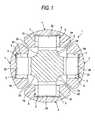
- FIG. 1 is an outline sectional view showing an essential portion of a cross joint according to an embodiment of the invention.
- a cross joint 1 is provided with a cross shaft member 2 integrally constituted with a base portion 2a and four pieces of shafts 2b arranged to project from the base portion 2a in a cross-like shape, and roller bearings 5 each having a bearing cup 4 as an outer ring member outwardly fitted to an outer side of an outer periphery of each of the shafts 2b via cylindrical rollers 3.
- the outer peripheral portions of the respective shafts 2b of the cross shaft member 2 are formed with inner ring race portions 2c with which the cylindrical rollers 3 are brought into rolling contact and the respective shafts 2b of the member 2 are made to function as inner ring members of corresponding ones of the roller bearings 5.
- the base portion 2a of the cross shaft member 2 is provided with shoulder portions 2d each having a section in a round-shape in which a center of a radius of curvature is set to an outer side of the base portion 2a and a center portion thereof is recessed to a side of a center portion of the base portion 2a, at respective intervals between necks (shaft necks) of twos of the shafts 2b contiguous to each other.
- An inside of the roller bearing 5 is constituted to be able to be hermetically sealed by attaching a seal member in a ring-like shape (not illustrated) to the shoulder portion 2d.
- the bearing cup 4 is provided with an outer ring race portion 4a and the cylindrical rollers 3 are rolled at inside of the cup 4. Further, the bearing cups 4 are attached to the roll or the drive shaft such that the roll of the steel rolling mill and the drive shaft are respectively connected to horizontal shafts and vertical shafts of the cross shafts comprising two pairs of the shafts 2b respectively aligned linearly (not illustrated). Rotation of the shaft is transmitted to the roll to rotate it in a state that the cross joint permits the roll to rock relative to the shaft axis. Further, the bearing cup 4 is provided with a grease nipple (not illustrated) and grease can pertinently be supplied to portions of the cylindrical rollers 3 rolling on the respective race portions 2c and 4a. Further, other than the above-described explanation, in place of the cylindrical roller 3, a needle-shape needle roller can also be used as a rolling member rolling between the respective race portions 2c and 4a.
- the cross shaft member 2 and the bearing cup 4 are constituted by using bearing steel of SUJ2 2 or the like or a steel material which is carburized or carbonitride by subjecting the material steel to high-frequency quenching or the like. Further, the race portion 2c and the shoulder portion 2d of the cross shaft member 2 and the race portion 4a of the bearing cup 4 are finished to predetermined accuracy by being subjected to finishing by cutting, machining, grinding or polishing. Further, the race portions 2c and 4a and the shoulder portion 2d are subjected to roller burnishing (deep rolling) after the finishing.
- roller burnishing while a mirror finish ball (mirror finished surface ball) made of ceramics held by, for example, hydraulic pressure is pressed to a surface of a working portion of the race portion 2c of the like to bring into rolling contact therewith by strong pressure, the mirror finish ball is moved on the surface of the working portion.
- working conditions of an amount of burnishing, press force and the like are selected such that, for example, hardness at a depth of at least 0.2mm from the surface of the working portion is work-hardened to be equal to or larger than Hv700 and a residual compressive stress at a depth of at least 0.3mm from the surface of the working portion becomes equal to or larger than 800 MPa.
- each race portion 2c after roller burnishing is ensured with a hardness equal to or larger than Hv700 at a depth of at least 0.2mm from the surface and is considerably harder than a product before roller burnishing and a shot-peened product.
- a surface hardness of the shot-peened product is more or less harder than that of each race portion 2c, the shot-peened product is deteriorated in the surface roughness after working (the surface is roughened) and needs postworking for smoothing the surface for making the cylindrical roller 3 roll in an oil-lubricated state.
- each race portion 2c since the surface is pressed by point contact with the mirror finish ball in roller burnishing, the surface hardness can be hardened while improving (reducing) the surface roughness by smoothly deforming the surface, and contrary to the shot-peened product, it is not necessary to subject the surface to postworking. Therefore, the surface hardness of each race portion 2c is substantially harder than that of the shot-peened product. Further, according to a test by the inventor of the application, it has been confirmed that the surface roughness of each race portion 2c by roller burnishing can be made to be equal to or less than a half of that before working in a maximum height roughness (Rmax) and a surface hardening coefficient can be increased compared with that before working. In this way, the fatigue strength of the race portion 2c can be increased by improving the surface hardening coefficient of the race portion 2c and increasing the surface hardness and surface originated flaking (surface layer flaking) at the race portion 2c can effectively be restrained from being brought about.
- Rmax maximum height roughness
- a residual compressive stress equal to or larger than 800MPa is generated at a depth of at least 0.3mm from the surface and work hardening is produced up to a depth about twice as much as that of the short-peened product.
- the cross joint 1 by subjecting the race portions 2c and 4a provided at the cross shaft member 2 and the bearing cup (outer ring member) 4 and the shoulder portion 2d of the cross shaft member 2 to roller burnishing, while improving roughnesses of the respective surfaces of the race portions 2c and 4a and the shoulder portion 2d, the surface harnesses can be increased and the residual compressive stresses immediately below the surfaces can be increased.
- exfoliation life of the race portions 2c and 4a can be prolonged and the fatigue strength of the race portions 2c and 4a and the shoulder portion 2d can be increased and therefore, long life formation of the cross joint 1 can be achieved.
- cross joint 1 is provided with the race portions 2c and 4a having long flaking life (life of rolling bearing) and provided with the cross shat member 2 and the bearing cup 4 having excellent fatigue strength, a cross joint used under a very severe condition by being integrated to a transmitting mechanism for transmitting high torque from a drive shaft to a driven shaft can simply be constituted.
- the residual compressive stress at the depth of at least 0.3mm from the respective surfaces of the race portions 2c and 4a and the shoulder portion 2d is made to be equal to or larger than 800MPa and therefore, in comparison with the above-described conventional product, the fatigue strength of the race portions 2c and 4a and the shoulder portion 4d can effectively be increased.
- the invention is not limited thereto but is applicable to various kinds of cross joints (universal joints) connected to, for example, a propeller shaft of an automobile and the like.
- each shoulder portion between two of the shaft neck portions of the cross shaft member (cross or spider) phases of which are shifted from each other by 90 degrees may be subjected to roller burnishing and the shape of the shoulder portion is not limited to the above-described at all.
- a cross shaft member or the like is constituted by carbon steel for mechanical structure of S54C of S55C or the like having a carbon content of, for example, 0.42 weight % or more, or a steel material hardened to a hardness of about HRC55 by subjecting the material steel to a heat treatment or a high-frequency quenching treatment and the race portion and the shoulder portion is subjected to roller burnishing.
- carbon steel for mechanical structure in this way, a cross shaft member having a fatigue strength substantially comparable to that of the conventional product comprising bearing steel and restraining material cost can easily be constituted and the cross joint can be fabricated at low cost.
- the invention constituted as described above achieves the following effects.
- the cross joint of the invention by subjecting the race portion and the shoulder portion of the cross shaft member to roller burnishing, the hardness of each of the surfaces of the race portion and the shoulder portion is increased and the residual compressive stress immediately before the surface is increased and therefore, in addition to that the roughness of each of the surfaces can be decreased, in comparison with the conventional product which is not subjected to roller burnishing, exfoliation life of the race portion can be prolonged, the fatigue strength of the cross shaft member can effectively be increased and therefore, long life formation of the cross joint can be achieved.
- the cross joint of the invention by subjecting the race portion of the outer ring member to roller burnishing, the hardness of the surface of the race portion is increased, the residual compressive stress immediately below the surface is increased and therefore, in addition to that the roughness of the surface can be increased, in comparison with the conventional product which is not subjected to roller burnishing, the exfoliation life of the race portion can be prolonged.
- the fatigue strength of the race portion and the shoulder portion can further effectively be increased and long life formation of the cross joint can further effectively be achieved.
- the life substantially comparable to that of the cross joint comprising bearing steel can be ensured by an inexpensive material.
Landscapes
- Engineering & Computer Science (AREA)
- Mechanical Engineering (AREA)
- General Engineering & Computer Science (AREA)
- Rolling Contact Bearings (AREA)
Abstract
Description
- The present invention relates to a cross joint (joint cross coupling, universal joint) used in a steel rolling mill or the like.
- In, for example, a steel rolling mill, a cross joint is interposed between a roll and a drive shaft for driving to rotate the roll, a steel rolling processing of the steel material can be carried out by rotating to move the role in accordance with rotation of the shaft while the roll is allowed to move in an up and down direction relative to a steel material which is being rolled. The cross joint includes: a cross shaft member (cross) having four pieces of shafts arranged in a cross-like shape; and a cross bearing which has a plurality of cylindrical rollers as rolling members aligned at surroundings of the respective shafts of the member, and a bearing cup as an outer ring mounted to an outer side of outer peripheries of the rollers. Each of outer peripheral portions of the shafts is used as an inner ring race portion. Further, according to the cross joint, the roll and the drive shaft are connected to a first shaft and a second shaft comprising respective pairs of shafts arranged on straight lines in the four pieces of the shafts respectively via the cross bearings and (rotational) torque from the shaft is transmitted to the roll via the cross joint.
- Meanwhile, according to the above-described conventional cross joint, such a cross shaft member and the bearing cup are provided, which are generally constituted by bearing steel of carburized steel or the like.
However, when large torque acts on the cross joint such as in the steel rolling mill, the joint is used under a very severe condition and there is a concern that even when the bearing steel is used, malfunction is brought about at an early stage. In details, the cylindrical roller is rolled on the inner ring race portion or the like formed at the cross shaft member under high contact surface pressure and therefore, exfoliation is liable to be brought about at the race portion. Further, according to the cross member, since the roll and the drive shaft are respectively connected to the contiguous pairs of shafts and therefore, large bending stress may be operated to a shoulder portion between shaft root (shaft neck) portions thereof and fatigue breaking of bending fatigue breaking or the like is liable to be brought about at the member. - In view of the above-described conventional problem, it is an object of the invention to provide a cross joint capable of prolonging rolling fatigue life of a rolling portion (life of rolling bearing), capable of increasing a fatigue strength of the cross joint and therefore, capable of achieving long life formation (ling fatigue life).
In order to solve the aforesaid object, the invention is characterized by having the following arrangement. - (1) A cross joint comprising:
- a cross shaft member including,
a four pieces of shafts each having a neck portion and a race portion, and
shoulder portions provided between adjacent two neck portions; - rolling members adapted to rotate around the race portions; and
- outer ring members fitted to the respective shafts via the rolling members, wherein the race portions and the shoulder portions are subjected to roller burnishing.
- (2) The cross joint according to (1), wherein a race portion formed on the outer ring member is subjected to roller burnishing.
- (3) The cross joint according to (1), wherein a residual compressive stress at a depth of at least 0.3mm from each of surfaces of the race portions and the shoulder portion subjected to the roller burnishing is made to be equal to or larger than 800 MPa.
- (4) The cross joint according to (1), wherein the cross shaft member and the outer ring member includes a carbon steel for a mechanical structure having a carbon content equal to or larger than 0.42 weight %.
- (5) A method of manufacturing a cross joint which includes:
- a cross shaft member including, a four pieces of shafts each having a neck portion and a race portion, and shoulder portions provided between adjacent two neck portions; rolling members adapted to rotate around the race portions; and outer ring members fitted to the respective shafts via the rolling members, the method comprising the step of subjecting the race portions and the shoulder portions to roller burnishing.
- (6) The method according to (5) further comprising the step of subjecting a race portion formed on the outer ring member to roller burnishing.
-
- According to the above-described cross joint, by subjecting the race portion and the shoulder portion of the cross shaft member to roller burnishing, the hardness of each of surfaces of the race portion and the shoulder portion can be increased and a residual compressive stress immediately below the surface can be increased. Further, a roughness of each of the surfaces can also be decreased.
According to the cross joint, the hardness of the surface of the race portion of the outer ring member can be increased and the residual compressive stress immediately below the surface can also be increased. Further, the roughness of the surface can also be decreased. - According to the cross joint, in comparison with the above-described conventional product, the fatigue strength of the race portion and the shoulder portion can further effectively be increased.
- According to the cross joint, the fatigue strength substantially comparable to that of the conventional bearing steel can be achieved.
-
- Fig. 1 is an outline sectional view showing an essential portion of a cross joint according to an embodiment of the invention.
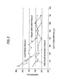
- Fig. 2 is a graph diagram showing a result of measuring a hardness at each depth from a surface of a race portion.
- Fig. 3 is a graph diagram showing a result of measuring a residual compressive stress at each depth from the surface of the race portion.
-
- A preferable embodiment showing a cross joint of the invention will be explained in reference to the drawings as follows. Further, in the following explanation, an explanation will be given of a case of applying the invention to a cross joint for driving a roll integrated into a steel rolling mill.
Fig. 1 is an outline sectional view showing an essential portion of a cross joint according to an embodiment of the invention. In the drawing, across joint 1 according to the embodiment is provided with across shaft member 2 integrally constituted with a base portion 2a and four pieces ofshafts 2b arranged to project from the base portion 2a in a cross-like shape, androller bearings 5 each having abearing cup 4 as an outer ring member outwardly fitted to an outer side of an outer periphery of each of theshafts 2b viacylindrical rollers 3. - The outer peripheral portions of the
respective shafts 2b of thecross shaft member 2 are formed with innerring race portions 2c with which thecylindrical rollers 3 are brought into rolling contact and therespective shafts 2b of themember 2 are made to function as inner ring members of corresponding ones of theroller bearings 5. The base portion 2a of thecross shaft member 2 is provided withshoulder portions 2d each having a section in a round-shape in which a center of a radius of curvature is set to an outer side of the base portion 2a and a center portion thereof is recessed to a side of a center portion of the base portion 2a, at respective intervals between necks (shaft necks) of twos of theshafts 2b contiguous to each other. An inside of the roller bearing 5 is constituted to be able to be hermetically sealed by attaching a seal member in a ring-like shape (not illustrated) to theshoulder portion 2d. - The
bearing cup 4 is provided with an outerring race portion 4a and thecylindrical rollers 3 are rolled at inside of thecup 4. Further, thebearing cups 4 are attached to the roll or the drive shaft such that the roll of the steel rolling mill and the drive shaft are respectively connected to horizontal shafts and vertical shafts of the cross shafts comprising two pairs of theshafts 2b respectively aligned linearly (not illustrated). Rotation of the shaft is transmitted to the roll to rotate it in a state that the cross joint permits the roll to rock relative to the shaft axis. Further, thebearing cup 4 is provided with a grease nipple (not illustrated) and grease can pertinently be supplied to portions of thecylindrical rollers 3 rolling on therespective race portions
Further, other than the above-described explanation, in place of thecylindrical roller 3, a needle-shape needle roller can also be used as a rolling member rolling between therespective race portions - The
cross shaft member 2 and thebearing cup 4 are constituted by using bearing steel ofSUJ2 2 or the like or a steel material which is carburized or carbonitride by subjecting the material steel to high-frequency quenching or the like. Further, therace portion 2c and theshoulder portion 2d of thecross shaft member 2 and therace portion 4a of thebearing cup 4 are finished to predetermined accuracy by being subjected to finishing by cutting, machining, grinding or polishing.
Further, therace portions shoulder portion 2d are subjected to roller burnishing (deep rolling) after the finishing. According to the roller burnishing, while a mirror finish ball (mirror finished surface ball) made of ceramics held by, for example, hydraulic pressure is pressed to a surface of a working portion of therace portion 2c of the like to bring into rolling contact therewith by strong pressure, the mirror finish ball is moved on the surface of the working portion. According to the roller burnishing, working conditions of an amount of burnishing, press force and the like are selected such that, for example, hardness at a depth of at least 0.2mm from the surface of the working portion is work-hardened to be equal to or larger than Hv700 and a residual compressive stress at a depth of at least 0.3mm from the surface of the working portion becomes equal to or larger than 800 MPa. - Here, a specific explanation will be given of operation and effect of the roller burnishing in reference to Fig. 2 and Fig. 3 showing an example of a result of a verifying test which has been carried out by the inventors and the like of the invention. Further, in the following explanation, an explanation will be given by exemplifying a verified result at the
race portion 2c on the side of thecross shaft member 2 and a mention will also be given of a measured result of a material only subjected to a carburizing treatment before roller burnishing and a material subjected to shot peening in addition to the carburizing treatment for comparison. - As has been apparent from Fig. 2, each
race portion 2c after roller burnishing is ensured with a hardness equal to or larger than Hv700 at a depth of at least 0.2mm from the surface and is considerably harder than a product before roller burnishing and a shot-peened product. Further, at a depth less than 0.1mm from surface, a surface hardness of the shot-peened product is more or less harder than that of eachrace portion 2c, the shot-peened product is deteriorated in the surface roughness after working (the surface is roughened) and needs postworking for smoothing the surface for making thecylindrical roller 3 roll in an oil-lubricated state. Specifically, according to the shot-peened product, it is necessary to remove a surface layer thereof at a depth of about 0.05mm from the surface by the postworking. - In contrast thereto, according to each
race portion 2c, since the surface is pressed by point contact with the mirror finish ball in roller burnishing, the surface hardness can be hardened while improving (reducing) the surface roughness by smoothly deforming the surface, and contrary to the shot-peened product, it is not necessary to subject the surface to postworking. Therefore, the surface hardness of eachrace portion 2c is substantially harder than that of the shot-peened product. Further, according to a test by the inventor of the application, it has been confirmed that the surface roughness of eachrace portion 2c by roller burnishing can be made to be equal to or less than a half of that before working in a maximum height roughness (Rmax) and a surface hardening coefficient can be increased compared with that before working. In this way, the fatigue strength of therace portion 2c can be increased by improving the surface hardening coefficient of therace portion 2c and increasing the surface hardness and surface originated flaking (surface layer flaking) at therace portion 2c can effectively be restrained from being brought about. - Further, as shown in Fig. 3, at each
race portion 2c, a residual compressive stress equal to or larger than 800MPa is generated at a depth of at least 0.3mm from the surface and work hardening is produced up to a depth about twice as much as that of the short-peened product. By producing the large residual compressive stress at therace portion 2c in this way, inner portion originated flaking at therace portion 2c can effectively be restrained from being brought about and the fatigue strength against stresses generated at inside of therace portion 2c can be increased. That is, at theshoulder portion 2d subjected to roller burnishing, the fatigue strength against bending stress operated by two of theshafts 2b continuous to theshoulder portion 2d can be increased and the bending fatigue breaking (fracture) can effectively be restrained from being brought about. - As described above, according to the cross joint 1 according to the embodiment, by subjecting the
race portions cross shaft member 2 and the bearing cup (outer ring member) 4 and theshoulder portion 2d of thecross shaft member 2 to roller burnishing, while improving roughnesses of the respective surfaces of therace portions shoulder portion 2d, the surface harnesses can be increased and the residual compressive stresses immediately below the surfaces can be increased. As a result, in comparison with the conventional product which is not subjected to roller burnishing, exfoliation life of therace portions race portions shoulder portion 2d can be increased and therefore, long life formation of the cross joint 1 can be achieved. Further, since the cross joint 1 is provided with therace portions member 2 and the bearingcup 4 having excellent fatigue strength, a cross joint used under a very severe condition by being integrated to a transmitting mechanism for transmitting high torque from a drive shaft to a driven shaft can simply be constituted. - Further, according to the embodiment, the residual compressive stress at the depth of at least 0.3mm from the respective surfaces of the
race portions shoulder portion 2d is made to be equal to or larger than 800MPa and therefore, in comparison with the above-described conventional product, the fatigue strength of therace portions - Further, although according to the above-described explanation, an explanation has been given of a case of applying to the cross joint integrated into the steel rolling mill, the invention is not limited thereto but is applicable to various kinds of cross joints (universal joints) connected to, for example, a propeller shaft of an automobile and the like.
Further, although according to the above-described explanation, an explanation has been given of the constitution in which the center of the radius of curvature is set on the outer side of the base portion 2a and the shoulder portion 2a having the section in the round-shape in which the central portion is recessed to the side of the center portion of the base portion 2a is subjected to roller burnishing, according to the invention, each shoulder portion between two of the shaft neck portions of the cross shaft member (cross or spider) phases of which are shifted from each other by 90 degrees may be subjected to roller burnishing and the shape of the shoulder portion is not limited to the above-described at all. Specifically, there may be constructed a constitution in which a shoulder portion having a section in a linear shape or a shoulder portion having a section in a round shape in which the center of a radius of curvature is set to a center side portion of a base portion such that a central portion thereof bulges to an outer side of the base portion is subjected to roller burnishing. - Further, although according to the above-described explanation, an explanation has been given of a case of constituting the
cross shaft member 2 and the bearingcup 4 by using bearing steel, the invention is not limited thereto but there may be constructed a constitution in which a cross shaft member or the like is constituted by carbon steel for mechanical structure of S54C of S55C or the like having a carbon content of, for example, 0.42 weight % or more, or a steel material hardened to a hardness of about HRC55 by subjecting the material steel to a heat treatment or a high-frequency quenching treatment and the race portion and the shoulder portion is subjected to roller burnishing. By using carbon steel for mechanical structure in this way, a cross shaft member having a fatigue strength substantially comparable to that of the conventional product comprising bearing steel and restraining material cost can easily be constituted and the cross joint can be fabricated at low cost. - The invention constituted as described above achieves the following effects.
According to the cross joint of the invention, by subjecting the race portion and the shoulder portion of the cross shaft member to roller burnishing, the hardness of each of the surfaces of the race portion and the shoulder portion is increased and the residual compressive stress immediately before the surface is increased and therefore, in addition to that the roughness of each of the surfaces can be decreased, in comparison with the conventional product which is not subjected to roller burnishing, exfoliation life of the race portion can be prolonged, the fatigue strength of the cross shaft member can effectively be increased and therefore, long life formation of the cross joint can be achieved. - Further, according to the cross joint of the invention, by subjecting the race portion of the outer ring member to roller burnishing, the hardness of the surface of the race portion is increased, the residual compressive stress immediately below the surface is increased and therefore, in addition to that the roughness of the surface can be increased, in comparison with the conventional product which is not subjected to roller burnishing, the exfoliation life of the race portion can be prolonged.
- Further, according to the cross joint of the invention, in comparison with the conventional product, the fatigue strength of the race portion and the shoulder portion can further effectively be increased and long life formation of the cross joint can further effectively be achieved.
Further, according to the cross joint of the invention, the life substantially comparable to that of the cross joint comprising bearing steel can be ensured by an inexpensive material.
Claims (6)
- A cross joint comprising:wherein the race portions and the shoulder portions are subjected to roller burnishing.a cross shaft member including,
a four pieces of shafts each having a neck portion and a race portion, and
shoulder portions provided between adjacent two neck portions;rolling members adapted to rotate on the race portions; andouter ring members fitted to the respective shafts via the rolling members, - The cross joint according to claim 1, wherein a race portion formed on the outer ring member is subjected to roller burnishing.
- The cross joint according to Claim 1, wherein a residual compressive stress at a depth of at least 0.3mm from each of surfaces of the race portions and the shoulder portion subjected to the roller burnishing is made to be equal to or larger than 800 MPa.
- The cross joint according to Claim 1, wherein the cross shaft member and the outer ring member includes a carbon steel for a mechanical structure having a carbon content equal to or larger than 0.42 weight %.
- A method of manufacturing a cross joint which includes:a cross shaft member including, a four pieces of shafts each having a neck portion and a race portion, and shoulder portions provided between adjacent two neck portions; rolling members adapted to rotate around the race portions; and outer ring members fitted to the respective shafts via the rolling members, the method comprising the step of subjecting the race portions and the shoulder portions to roller burnishing.
- The method according to claim 5 further comprising the step of subjecting a race portion formed on the outer ring member to roller burnishing.
Applications Claiming Priority (2)
| Application Number | Priority Date | Filing Date | Title |
|---|---|---|---|
| JP2002268761A JP2004108407A (en) | 2002-09-13 | 2002-09-13 | Cruciform shaft joint |
| JP2002268761 | 2002-09-13 |
Publications (2)
| Publication Number | Publication Date |
|---|---|
| EP1398111A1 true EP1398111A1 (en) | 2004-03-17 |
| EP1398111B1 EP1398111B1 (en) | 2008-04-16 |
Family
ID=31884821
Family Applications (1)
| Application Number | Title | Priority Date | Filing Date |
|---|---|---|---|
| EP03020801A Expired - Lifetime EP1398111B1 (en) | 2002-09-13 | 2003-09-12 | Universal cross joint |
Country Status (4)
| Country | Link |
|---|---|
| US (2) | US7163461B2 (en) |
| EP (1) | EP1398111B1 (en) |
| JP (1) | JP2004108407A (en) |
| DE (1) | DE60320352T2 (en) |
Cited By (2)
| Publication number | Priority date | Publication date | Assignee | Title |
|---|---|---|---|---|
| FR2867706A1 (en) * | 2004-03-17 | 2005-09-23 | Visteon Global Tech Inc | PROCESS FOR FINISHING A GROSS METAL PIECE |
| WO2016172032A1 (en) * | 2015-04-23 | 2016-10-27 | The Timken Company | Method of forming a bearing component |
Families Citing this family (7)
| Publication number | Priority date | Publication date | Assignee | Title |
|---|---|---|---|---|
| JP2006077874A (en) * | 2004-09-09 | 2006-03-23 | Jtekt Corp | Universal joint |
| EP2275759B1 (en) | 2006-09-20 | 2013-02-13 | LG Electronics Inc. | Refrigerator |
| CN101303071B (en) * | 2007-05-08 | 2010-08-18 | 京瓷美达株式会社 | Traction-drive type driving-force transmission mechanism and image forming apparatus equipped therewith |
| TWI381609B (en) * | 2007-11-07 | 2013-01-01 | 創見資訊股份有限公司 | Portable electronic device and charging circuit thereof and charging method thereof |
| JP5429394B2 (en) * | 2010-09-27 | 2014-02-26 | 日本精工株式会社 | Outer ring for shell type radial needle bearing and manufacturing method thereof |
| DE102016209782A1 (en) * | 2016-06-03 | 2017-12-07 | Schaeffler Technologies AG & Co. KG | Carbonitriding of universal joint bushes |
| US12331797B2 (en) | 2020-05-26 | 2025-06-17 | Aircraft Gear Corporation | Method of carburizing driveline components |
Citations (3)
| Publication number | Priority date | Publication date | Assignee | Title |
|---|---|---|---|---|
| GB832784A (en) * | 1956-03-19 | 1960-04-13 | Gelenkwellenbau Gmbh | Improvements in and relating to universal joints |
| GB2117088A (en) * | 1982-03-22 | 1983-10-05 | Dana Corp | Universal joint components |
| US5538473A (en) * | 1992-12-08 | 1996-07-23 | Gkn Automotive Ag | Constant velocity universal joint |
Family Cites Families (10)
| Publication number | Priority date | Publication date | Assignee | Title |
|---|---|---|---|---|
| US1630898A (en) * | 1923-11-15 | 1927-05-31 | Cleveland Universal Parts Comp | Universal joint |
| US3039183A (en) * | 1958-06-09 | 1962-06-19 | Borg Warner | Universal joint |
| US3655466A (en) * | 1968-10-31 | 1972-04-11 | Alexandr Moiseevich Bysink | Universal joint cross of power transmissions and a method of its heat treatment |
| US4090796A (en) * | 1977-07-23 | 1978-05-23 | Koyo Seiko Company, Limited | Device for fastening needle case to yoke in universal joint of trunnion type |
| US4869616A (en) * | 1984-03-26 | 1989-09-26 | The Torrington Company | Universal joint cross |
| EP0869533B1 (en) * | 1996-09-18 | 2003-11-19 | Kabushiki Kaisha Toshiba | X-ray image tube and method for manufacturing the same |
| US6390924B1 (en) * | 1999-01-12 | 2002-05-21 | Ntn Corporation | Power transmission shaft and constant velocity joint |
| US6478682B1 (en) * | 1999-11-05 | 2002-11-12 | Ntn Corporation | Constant velocity universal joint |
| RU2176754C1 (en) * | 2001-04-12 | 2001-12-10 | Закрытое Акционерное Общество "Техмаш" | Propeller shaft universal joint |
| CA2465201C (en) * | 2001-11-02 | 2009-10-20 | The Boeing Company | Apparatus and method for forming weld joints having compressive residual stress patterns |
-
2002
- 2002-09-13 JP JP2002268761A patent/JP2004108407A/en active Pending
-
2003
- 2003-09-12 US US10/660,754 patent/US7163461B2/en not_active Expired - Fee Related
- 2003-09-12 DE DE60320352T patent/DE60320352T2/en not_active Expired - Lifetime
- 2003-09-12 EP EP03020801A patent/EP1398111B1/en not_active Expired - Lifetime
-
2006
- 2006-12-06 US US11/634,080 patent/US20070077869A1/en not_active Abandoned
Patent Citations (3)
| Publication number | Priority date | Publication date | Assignee | Title |
|---|---|---|---|---|
| GB832784A (en) * | 1956-03-19 | 1960-04-13 | Gelenkwellenbau Gmbh | Improvements in and relating to universal joints |
| GB2117088A (en) * | 1982-03-22 | 1983-10-05 | Dana Corp | Universal joint components |
| US5538473A (en) * | 1992-12-08 | 1996-07-23 | Gkn Automotive Ag | Constant velocity universal joint |
Cited By (3)
| Publication number | Priority date | Publication date | Assignee | Title |
|---|---|---|---|---|
| FR2867706A1 (en) * | 2004-03-17 | 2005-09-23 | Visteon Global Tech Inc | PROCESS FOR FINISHING A GROSS METAL PIECE |
| WO2016172032A1 (en) * | 2015-04-23 | 2016-10-27 | The Timken Company | Method of forming a bearing component |
| US9810264B2 (en) | 2015-04-23 | 2017-11-07 | The Timken Company | Method of forming a bearing component |
Also Published As
| Publication number | Publication date |
|---|---|
| EP1398111B1 (en) | 2008-04-16 |
| DE60320352D1 (en) | 2008-05-29 |
| US20040053700A1 (en) | 2004-03-18 |
| JP2004108407A (en) | 2004-04-08 |
| DE60320352T2 (en) | 2009-05-07 |
| US7163461B2 (en) | 2007-01-16 |
| US20070077869A1 (en) | 2007-04-05 |
Similar Documents
| Publication | Publication Date | Title |
|---|---|---|
| US7685717B2 (en) | Method for manufacturing a bearing raceway member | |
| US5333954A (en) | Rolling/sliding part | |
| US7163461B2 (en) | Cross joint | |
| US11371559B2 (en) | Rolling component, bearing, and method of manufacturing the same | |
| EP2881605B1 (en) | Cage for constant-velocity universal joint, fixed type constant-velocity universal joint incorporating same, and drive shaft incorporating said fixed type constant-velocity universal joint | |
| CN100447439C (en) | Constant velocity universal joint | |
| JP2005106234A (en) | Conical roller bearing and method for working conical roller bearing | |
| JP2004116569A (en) | Rolling bearing | |
| JP3424035B2 (en) | Outer ring of constant velocity ball joint | |
| JP5284904B2 (en) | Manufacturing method of universal joint parts | |
| US6381829B2 (en) | Method for making an improved main shaft for a coal pulverizer by employing a ceramic coating thereon | |
| JP4284951B2 (en) | Method of manufacturing bearing ring for ball bearing | |
| US6176806B1 (en) | Cam disk for toroidal type continuously variable transmission | |
| KR20140024080A (en) | Universal joint for vehicle and manufacturing method thereof | |
| JPH0942303A (en) | Constant velocity universal joint | |
| JP2006144934A (en) | Power transmission shaft | |
| JP2729949B2 (en) | Burnishing tool | |
| WO2019103039A1 (en) | Rolling part, bearing, and production method therefor | |
| JP2020197288A (en) | bearing | |
| JP2019095044A (en) | Rolling component, bearing and manufacturing method of these items | |
| JP2022020804A (en) | Constant velocity universal joint and its cage | |
| JP2004044787A (en) | Method for manufacturing bearing raceway member | |
| CN111133211B (en) | Constant velocity universal joint and spacer thereof | |
| EP4108942A1 (en) | Rolling bearing and method for producing same | |
| US6374477B1 (en) | Method for working input shaft for toroidal-type continuously variable transmission |
Legal Events
| Date | Code | Title | Description |
|---|---|---|---|
| PUAI | Public reference made under article 153(3) epc to a published international application that has entered the european phase |
Free format text: ORIGINAL CODE: 0009012 |
|
| AK | Designated contracting states |
Kind code of ref document: A1 Designated state(s): AT BE BG CH CY CZ DE DK EE ES FI FR GB GR HU IE IT LI LU MC NL PT RO SE SI SK TR |
|
| AX | Request for extension of the european patent |
Extension state: AL LT LV MK |
|
| 17P | Request for examination filed |
Effective date: 20040414 |
|
| 17Q | First examination report despatched |
Effective date: 20040921 |
|
| AKX | Designation fees paid |
Designated state(s): DE FR GB |
|
| RAP1 | Party data changed (applicant data changed or rights of an application transferred) |
Owner name: JTEKT CORPORATION |
|
| GRAP | Despatch of communication of intention to grant a patent |
Free format text: ORIGINAL CODE: EPIDOSNIGR1 |
|
| RIC1 | Information provided on ipc code assigned before grant |
Ipc: F16D 3/40 20060101ALN20070928BHEP Ipc: F16C 21/00 20060101ALN20070928BHEP Ipc: B24B 39/00 20060101AFI20070928BHEP |
|
| GRAS | Grant fee paid |
Free format text: ORIGINAL CODE: EPIDOSNIGR3 |
|
| GRAA | (expected) grant |
Free format text: ORIGINAL CODE: 0009210 |
|
| AK | Designated contracting states |
Kind code of ref document: B1 Designated state(s): DE FR GB |
|
| RIN1 | Information on inventor provided before grant (corrected) |
Inventor name: OZEKI, MITSUMASA,KOYO MACHINE INDUSTRIES CO., LTD. Inventor name: KOMEYAMA, NOBUO,JTEKT CORPORATION |
|
| REF | Corresponds to: |
Ref document number: 60320352 Country of ref document: DE Date of ref document: 20080529 Kind code of ref document: P |
|
| ET | Fr: translation filed | ||
| PLBE | No opposition filed within time limit |
Free format text: ORIGINAL CODE: 0009261 |
|
| STAA | Information on the status of an ep patent application or granted ep patent |
Free format text: STATUS: NO OPPOSITION FILED WITHIN TIME LIMIT |
|
| 26N | No opposition filed |
Effective date: 20090119 |
|
| GBPC | Gb: european patent ceased through non-payment of renewal fee |
Effective date: 20080912 |
|
| PG25 | Lapsed in a contracting state [announced via postgrant information from national office to epo] |
Ref country code: GB Free format text: LAPSE BECAUSE OF NON-PAYMENT OF DUE FEES Effective date: 20080912 |
|
| REG | Reference to a national code |
Ref country code: FR Ref legal event code: PLFP Year of fee payment: 13 |
|
| PGFP | Annual fee paid to national office [announced via postgrant information from national office to epo] |
Ref country code: FR Payment date: 20150629 Year of fee payment: 13 |
|
| REG | Reference to a national code |
Ref country code: FR Ref legal event code: ST Effective date: 20170531 |
|
| PG25 | Lapsed in a contracting state [announced via postgrant information from national office to epo] |
Ref country code: FR Free format text: LAPSE BECAUSE OF NON-PAYMENT OF DUE FEES Effective date: 20160930 |
|
| PGFP | Annual fee paid to national office [announced via postgrant information from national office to epo] |
Ref country code: DE Payment date: 20220803 Year of fee payment: 20 |
|
| REG | Reference to a national code |
Ref country code: DE Ref legal event code: R071 Ref document number: 60320352 Country of ref document: DE |