EP1398004A2 - Cleaning device for medical instrument - Google Patents
Cleaning device for medical instrument Download PDFInfo
- Publication number
- EP1398004A2 EP1398004A2 EP03020413A EP03020413A EP1398004A2 EP 1398004 A2 EP1398004 A2 EP 1398004A2 EP 03020413 A EP03020413 A EP 03020413A EP 03020413 A EP03020413 A EP 03020413A EP 1398004 A2 EP1398004 A2 EP 1398004A2
- Authority
- EP
- European Patent Office
- Prior art keywords
- cleaning
- containing portion
- water supply
- medical instrument
- treatment
- Prior art date
- Legal status (The legal status is an assumption and is not a legal conclusion. Google has not performed a legal analysis and makes no representation as to the accuracy of the status listed.)
- Granted
Links
Images





Classifications
-
- A—HUMAN NECESSITIES
- A61—MEDICAL OR VETERINARY SCIENCE; HYGIENE
- A61B—DIAGNOSIS; SURGERY; IDENTIFICATION
- A61B90/00—Instruments, implements or accessories specially adapted for surgery or diagnosis and not covered by any of the groups A61B1/00 - A61B50/00, e.g. for luxation treatment or for protecting wound edges
- A61B90/70—Cleaning devices specially adapted for surgical instruments
-
- A—HUMAN NECESSITIES
- A61—MEDICAL OR VETERINARY SCIENCE; HYGIENE
- A61B—DIAGNOSIS; SURGERY; IDENTIFICATION
- A61B17/00—Surgical instruments, devices or methods
- A61B17/28—Surgical forceps
- A61B17/29—Forceps for use in minimally invasive surgery
-
- A—HUMAN NECESSITIES
- A61—MEDICAL OR VETERINARY SCIENCE; HYGIENE
- A61B—DIAGNOSIS; SURGERY; IDENTIFICATION
- A61B90/00—Instruments, implements or accessories specially adapted for surgery or diagnosis and not covered by any of the groups A61B1/00 - A61B50/00, e.g. for luxation treatment or for protecting wound edges
- A61B90/70—Cleaning devices specially adapted for surgical instruments
- A61B2090/701—Cleaning devices specially adapted for surgical instruments for flexible tubular instruments, e.g. endoscopes
Definitions
- the present invention relates to a device for cleaning medical instruments including treatment portions in insertion portions.
- the ultrasonic treatment instrument includes a handle unit including an insertion portion, a probe unit attached to the handle unit, and a vibrator unit for driving a probe.
- a jaw which is an open/close member for grasping the ultrasonic treatment instrument is attached to a tip end of the insertion portion of the handle unit. This jaw is connected to an operation rod inserted in a channel formed in the insertion portion of the handle unit, and is rotated/operated, when the operation rod is moved forwards/backwards by a handle of the handle unit.
- a probe of the probe unit is inserted through the insertion portion of the handle unit, and the distal-end portion of the probe is disposed opposite to the jaw.
- a tissue is treated by the distal-end portion of the probe and the jaw.
- An object of the present invention is to provide a cleaning device for a medical instrument, capable of efficiently cleaning a treatment portion of the medical instrument which easily becomes dirty.
- a cleaning device which cleans a treatment portion of a medical instrument, comprising:
- a cleaning device which cleans a treatment portion of a medical instrument, comprising:
- a cleaning device which cleans a treatment portion of a medical instrument, comprising:
- a cleaning device for a surgical treatment instrument according to a first embodiment of the present invention will be described as a medical device.
- the surgical treatment instrument which is a cleaning object in the present embodiment is an ultrasonic treatment instrument 1.
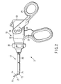
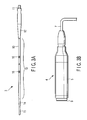
- the ultrasonic treatment instrument 1 includes a handle unit 2 shown in FIG. 2, a probe unit 3 shown in FIG. 3A, and a vibrator unit 4 shown in FIG. 3B. When the ultrasonic treatment instrument 1 is used, the respective units 2, 3, 4 are assembled as shown in FIG. 1.
- the vibrator unit 4 includes a cylindrical exterior cover 5, and an ultrasonic vibrator and horn (not shown) are disposed in the exterior cover 5.
- a hand piece cord 7 to be electrically connected to a power supply (not shown) is connected to a base end of the vibrator unit 4.
- a power for driving is supplied to the ultrasonic vibrator from the power supply via the hand piece cord 7 to drive the ultrasonic vibrator.
- a connection portion 9 to be connected to the handle unit 2 is formed in a front peripheral edge of the vibrator unit 4.
- the probe unit 3 includes a rod-shaped vibration transmission member 10, and ultrasonic vibration generated in the ultrasonic vibrator of the vibrator unit 4 is transmitted to a distal-end treatment portion by this rod-shaped vibration transmission member 10.
- a male screw 11 to be screwed in a female screw formed in the tip end of the horn is formed in a proximate-end position of the vibration transmission member 10.
- the vibration transmission member 10 includes: a conical proximate-end horn 12 for enlarging an amplitude of the ultrasonic vibration amplified by the horn on the side of the vibrator unit 4 further into a second stage; a middle portion 13 positioned on the side of a tip end of the proximate-end horn 12; a conical distal-end horn 14, positioned on the side of the tip end of the middle portion 13, for enlarging the amplitude of the ultrasonic vibration amplified by the proximate-end horn 12 into a final stage; and a cylindrical tip end 15 positioned on the side of the tip end of the distal-end horn 14.
- the ultrasonic vibration generated in the ultrasonic vibrator is gradually amplified by the horn of the vibrator unit 4, the proximate-end horn 12 in the vibration transmission member 10, and the distal-end horn 14, and is transmitted to the tip end 15 of the vibration transmission member 10.
- a plurality of flange-shaped support members 16 are positioned in second and subsequent nodes on the side of the tip end of the transmitted ultrasonic vibration.
- the handle unit 2 includes an operation portion 19, an insertion sheath portion 17 including a longitudinal overcoat tube 20 rotatably attached to the operation portion 19, and a distal-end function portion (treatment portion) 21 disposed in the tip end of the insertion sheath portion 17.
- the operation portion 19 of the handle unit 2 includes an operation portion main body 22, a fixed handle 23 formed integrally with the operation portion main body 22, and a movable handle 25 rotatably attached to the operation portion main body 22 via a handle support shaft 24.
- a cylindrical joint member 32 disposed in the operation portion main body 22 via a pipe fixing member 31 is fixed/connected to the proximate-end portion of the insertion sheath portion 17.
- the joint member 32 is attached to the operation portion main body 22 by a fixing ring 33 so as to rotatable around an insertion portion axis.
- a rotary operation knob 34 is fixed to the joint member 32. When the rotary operation knob 34 is rotated/operated, the insertion sheath portion 17 can be rotated/operated around a sheath axis.
- a cylindrical driving force transmission intermediate member 38 to be connected to an operation rod 60 described later is fitted in the joint member 32 so as to be movable in an insertion portion axial direction.
- a pin 39 is attached to a rear-end portion of the driving force transmission intermediate member 38. This pin 39 is fitted/engaged in a guide groove 41 which is cut/formed in the joint member 32 so as to extend in the insertion portion axial direction. This regulates the rotation of the driving force transmission intermediate member 38 and allows only the movement into the insertion portion axial direction.
- An O ring 42 is fitted around the outer periphery of the distal-end portion of the driving force transmission intermediate member 38, and the O ring 42 is disposed between the driving force transmission intermediate member 38 and joint member 32.
- a distal-end outer peripheral portion of a slider receiver member 45 is screwed in the driving force transmission intermediate member 38, and both the portion and the member are coaxially assembled/fixed.
- a slider member 46 is slidably fitted in the outer periphery of the driving force transmission intermediate member 38 on the side of the rear end.
- a coiled spring 47 is wound around the outer periphery of the slider receiver member 45 between the driving force transmission intermediate member 38 and the slider member 46.
- a first packing 48 in the form of the O ring is attached to the inner surface of the driving force transmission intermediate member 38.
- the first packing 48 is bonded to the outer periphery of the vibration transmission member 10 of the probe unit 3 to hold the vibration transmission member 10 and to close a gap between the units.
- a second packing 49 having the O-ring shape is also attached to a hand-side end of the slider receiver member 45.
- the second packing 49 is bonded to the outer periphery of the vibration transmission member 10 of the probe unit 3 to hold the vibration transmission member 10 and to close the gap between the units.
- the packings 48, 49 are disposed in this manner, for example, aeroperitoneum gas at the time of a surgical operation under an abdominoscope can be prevented from passing through an inner gap from an insertion portion tip end and leaking. Since two packings 48, 49 are both formed of a rubber, and elastic, the vibration transmission member 10 to ultrasonically vibrate is steadily supported without any difficulty.
- An engaging pin 51 to engage with the slider member 46 in the operation portion main body 22 is disposed in the movable handle 25 of the handle unit 2.
- the movement of the movable handle 25 is transmitted to the slider member 46 via the engaging pin 51.
- the helical compression spring 47 is constantly attached in a compressed/urged state, a certain or more operation force applied to the movable handle 25 in a closing direction is absorbed by deformation of the helical compression spring 47. Accordingly, the slider receiver member 45 is slid/operated in a state in which an overload applied to the slider receiver member 45 is prevented.
- a vibrator connection portion 52 for detachably attaching the vibrator unit 4 is disposed in a rear-end portion of the handle unit 2 in the operation portion main body 22.
- the vibrator connection portion 52 includes a cylindrically formed frame member 53 and a cylindrical connection member 54.
- the frame member 53 and connection member 54 are screwed/fixed into the inner surface of the operation portion main body 22.
- a screwed/fixed portion of the frame member 53 is positioned before the connection member 54.
- the rear-end portion of the frame member 53 is concentrically disposed inside the connection member 54.
- connection portion 9 of the vibrator unit 4 is fitted into/engaged with a distal-end engagement portion 55 of the frame member 53, so that the vibrator unit 4 is fixed to the handle unit 2.
- the connection portion 9 is formed, for example, by a C ring so as to swell outwards.
- a plurality of through-holes 56 are appropriately scattered and disposed in a wall portion of the frame member 53.
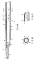
- the overcoat tube 20 of the insertion sheath portion 17 includes an outer pipe (overcoat tube) 61 and an inner pipe 62, and the outer periphery of the outer pipe 61 is subjected to an electric insulating treatment by an insulating tube 63. In the electric insulation, the insertion sheath portion 17 may also be subjected to treatment means such as coating.
- the outer pipe 61 includes a main channel 65 for passing the vibration transmission member 10 of the probe unit 3, and a sub-channel 66 for passing the operation rod 60. Similarly, as shown in FIG.
- a part of a circular sectional portion is crushed to be flat to form a gap as the sub-channel 66 between the section and the inner surface of the outer pipe 61.
- a through-hole 67 is formed in one or more appropriate portions of the inner pipe 62 disposed opposite to the sub-channel 66, so that the main channel 65 can be connected to the sub-channel 66.
- the distal-end function portion 21 of the handle unit 2 includes a distal-end chip member 71 attached to the distal-end portion of the outer pipe 61 and formed, for example, of a metal, and a single swing hold member 74 rotatably attached to the distal-end chip member 71 via a support shaft 72.
- This hold member 74 holds a grasp member 75.
- the tip end of the operation rod 60 is connected to the proximate-end portion of the hold member 74 via a support shaft 76.
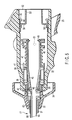
- the cleaning device 80 includes a cleaning cover 81 which has an elongated shape.
- a cleaning cover 81 which has an elongated shape.
- an outer pipe 82 and inner pipe 83 are concentrically disposed and constituted in a double tube form, and a cylindrical member is constituted which can surround and contain a cleaning object portion of the ultrasonic treatment instrument 1.
- Both tip ends of the outer pipe 82 and inner pipe 83 are detachably fixed to a distal-end member 85 constituted of a cylindrical member including a relatively thick wall.
- Both rear ends of the outer pipe 82 and inner pipe 83 are detachably fixed to a nozzle member 86 constituted of a cylindrical member including a relatively thick wall.
- a peripheral edge in the tip end of the outer pipe 82 is screwed in a rear edge of the distal-end member 85.
- a peripheral edge in the tip end of the nozzle member 86 is screwed in a rear-end outer peripheral edge of the outer pipe 82.
- the outer pipe 82 is connected to the distal-end member 85 in a liquid-tight manner.
- the outer pipe 82 is also connected to the nozzle member 86 in the liquid-tight manner.
- the distal-end portion of the inner pipe 83 is fitted into the distal-end member 85 in the liquid-tight manner.
- the rear-end portion of the outer pipe 82 is fitted into the nozzle member 86 in the liquid-tight manner.
- the outer pipe 82 and inner pipe 83 are formed by transparent materials so that the inside can be seen through.
- the distal-end member 85 and nozzle member 86 may also be formed of the transparent materials, but are formed of metals and are opaque herein. In the present specification, the nozzle does not mean that the nozzle is limited to the metal material.
- a plurality of jet ports (water supply nozzle ports) 87 are arranged at equal intervals in a circumferential direction of the pipe, and a plurality of arrays of jet ports 87 are arranged and formed in a pipe axial direction.
- a region in the inner pipe 83 where a plurality of jet ports 87 are arranged forms a cleaning region (containing portion) 88 for containing/arranging the cleaning object of the ultrasonic treatment instrument 1.
- a gap is made in the outer pipe 82 and inner pipe 83, and this gap forms a supply channel 89 for distributing the cleaning water to the respective jet ports 87.
- An inner hole of the distal-end member 85 forms a drain port 90 leading into the cleaning cover 81.
- the cleaning water in the cleaning cover 81 is drained to the outside by the drain port 90.
- One or more supply nozzles 91 are attachment the nozzle member 86.
- the cleaning water is supplied to the supply channel 89 via the respective supply nozzles 91.
- Two water supply tubes (not shown) connected to a water supply such as a water supply tank and pump incorporated in the cleaning machine for the treatment instrument can separately be connected to each supply nozzle 91.
- Fixing means attached to the distal-end portion of the surgical treatment instrument, for holding the cleaning cover 81 is disposed in the rear-end portion of the nozzle member 86.
- the inner hole of the rear-end portion of the nozzle member 86 constitutes an insertion port for inserting the distal-end portion of the surgical treatment instrument.
- An elastic tube 92 is fitted into the inner hole of the rear-end portion of the nozzle member 86.
- an abutment portion 93 for receiving an inner end of the elastic tube 92 is formed in an inner end of a region in which the elastic tube 92 is fitted.
- a push-in ring 95 is screwed into the rear-end portion of the nozzle member 86.
- a flange 96 of the push-in ring 95 is brought into contact with an outer end of the elastic tube 92, and the push-in ring 95 is screwed into the nozzle member 86. Then, the elastic tube 92 is pushed in the axial direction, and the elastic tube 92 is compressed in the axial direction, so that an inner diameter of the elastic tube 92 can be reduced.
- An engagement portion is constituted to engage with the portion of the medical instrument 1 inserted via the insertion port constituted of the nozzle member 86 and to hole the medical instrument 1 in the cleaning cover 81.
- the handle unit 2, treatment probe, and generation unit are assembled to use the ultrasonic treatment instrument 1 in the state shown in FIG. 1. Moreover, when the ultrasonic treatment instrument 1 is used, the ultrasonic treatment instrument 1 becomes dirty. Therefore, the instrument needs to be cleaned every use.
- the treatment portion such as the distal-end function portion 21 includes concave/convex portions and gaps. Since the portion has an especially complicated shape, degree of adhesion of dirt is strong. To remove the dirt from this portion, the cleaning efficiency is bad only with the shower cleaning or the exposure to the running water.
- the cleaning device 80 of the present embodiment is used to remove the dirt of the distal-end function portion 21.
- the distal-end portion of the handle unit 2 in the insertion sheath portion 17 is covered with the cleaning cover 81, and the device is attached. That is, as shown in FIGS. 7A and 7B, the distal-end portion of the insertion sheath portion 17 of the handle unit 2 from which the probe unit 3 has been removed is inserted into the cleaning cover 81 of the cleaning device 80 to position the distal-end function portion (treatment portion) 21 in the cleaning region 88.
- the push-in ring 95 is screwed in, the elastic tube 92 is compressed in the axial direction by the flange 96 of the push-in ring 95, and the inner diameter of the elastic tube 92 is reduced. Then, the elastic tube 92 tightens the outer periphery of the insertion sheath portion 17 inserted into the tube, and the cleaning cover 81 is fixed to the insertion sheath portion 17. Since the insertion sheath portion 17 is elastically fastened by the elastic tube 92 in this manner, an outer surface treatment layer of the insertion sheath portion 17 protected by the insulating tube 63 can be prevented from being damaged.
- supply tube line means such as a water supply tube connected to the water supply is individually connected to the respective supply nozzles 91.
- the water supply it is possible to use the water supply tank or pump incorporated in the cleaning machine for the treatment instrument in which the treatment instruments such as the ultrasonic treatment instrument are disposed to carry out the shower cleaning or running water cleaning.
- the water supply tube (not shown) connected to the water supply is connected to the supply nozzle 91.
- the high-pressure cleaning water pressurized from the water supply through the water supply tube is distributed to the jet ports (water supply nozzle ports) 87 through the supply passage 89, and the high-pressure cleaning water from the periphery is spouted toward the distal-end function portion (treatment portion) 21 positioned in the cleaning region 88 from the respective jet ports 87. Since the high-pressure cleaning water is vigorously spouted onto the distal-end function portion 21 from the periphery, solid dirt can be removed, and further every corner can securely be cleaned without any unevenness. Since the cleaning water is supplied to the supply channel 89 from a plurality of supply nozzles 91, the high-pressure cleaning water can uniformly be distributed to the respective jet ports 87, and all the circumference can strongly be cleaned.
- the ultrasonic treatment instrument 1 together with the attached cleaning device 80 is installed in a cleaning tank of the cleaning machine or a cleaning tray of a cleaning unit, and an exterior portion of the ultrasonic treatment instrument 1 is preferably subjected to the shower cleaning or exposed to the running water and is also cleaned.
- the respective components of the cleaning device 80 can all be disassembled. Especially, the distal-end member 85, nozzle member 86, outer pipe 82, and inner pipe 83 can easily be disassembled, when the distal-end member 85 and nozzle member 86 are removed from the outer pipe 82. Therefore, the components of the cleaning device 80 can also easily be cleaned.
- FIGS. 9 and 10 The cleaning device according to a second embodiment of the present invention will be described with reference to FIGS. 9 and 10.
- the same components as those of the first embodiment are denoted with the same reference numerals, and the detailed description is omitted.
- a front-end plate 102 and rear-end plate 103 are attached to front and rear ends of a cylindrical member 101 to close openings of the cylindrical member 101. Accordingly, a cleaning cover 104 is constituted to surround the cleaning region.
- the front-end plate 102 and rear-end plate 103 are screwed into and attached to the front-end and rear-end portions of the cylindrical member 101 so as to be attachable/detachable.
- Fixing means which engages with the distal-end portion of the surgical treatment instrument to hole the cleaning cover 104 in the surgical treatment instrument is disposed in the rear-end plate 103.
- the fixing means includes a hold cylinder 115 for passing the insertion sheath portion 17 of the ultrasonic treatment instrument 1, the hold cylinder 115 is disposed coaxially with the cleaning cover 104, and the insertion sheath portion 17 of the ultrasonic treatment instrument 1 is passed through the cylinder.
- a front end of the hold cylinder 115 is screwed into the rear-end plate 103, and the hold cylinder is fixed to the rear-end plate 103 so as to be attachable/detachable.
- an elastic tube 116 is fitted into the hold cylinder 115.
- a part of the outer periphery of the elastic tube 116 is meshed with a screw portion 117 formed in the inner surface of the hold cylinder 115, and is bonded if necessary. Accordingly, the elastic tube 116 is fixed to the hold cylinder 115.
- the elastic tube 116 contacts the outer periphery of the insertion sheath portion 17 with pressure, and engages with the insertion sheath portion 17.
- a supply nozzle 121 is disposed coaxially with the cleaning cover 104 in the front-end plate 102 of the cleaning cover 104, screwed into the front-end plate 102, and accordingly attached.
- the supply tube line means such as the water supply tube connected to the water supply is connected to the supply nozzle 121.
- a water supply port 122 is formed and opened toward the cleaning region in the cleaning cover 104.
- the supply nozzle 121 and hold cylinder 115 are arranged on a central axis of the cleaning cover 104, and a hold axis by the hold cylinder 115 is constituted so as to agree with a jet direction of the water supply port 122.
- Drain ports 125 are formed in the cylindrical member 101, front-end plate 102, and rear-end plate 103 of the cleaning cover 104, respectively, and the cleaning water which has overflowed in the cleaning region in the cleaning cover 104 is drained to the outside of the cleaning cover 104 via the drain ports 125.
- the distal-end portion of the insertion sheath portion 17 in the handle unit 2 from which the probe unit 3 has been removed is inserted into the hold cylinder 115 to position the distal-end function portion (treatment portion) 21 in the cleaning region in the cleaning cover 104.
- the high-pressure cleaning water is directed toward the cleaning region in the cleaning cover 104 from the water supply port 122 opened in an inner end of the supply nozzle 121 and spouted onto the distal-end function portion 21. Since the high-pressure cleaning water is vigorously spouted onto the distal-end function portion 21, even greasy dirt is removed.
- the cleaning water which has overflowed into the cleaning cover 104 is drained to the outside of the cleaning cover 104 via the drain ports 125.
- the drain ports 125 are formed in the respective wall portions of the cleaning cover 104 surrounding the cleaning object. Therefore, even when the cleaning cover 104 is disposed in any arrangement, the cleaning water can be drained to the outside of the cleaning cover 104 through any drain port 125. Therefore, the cleaning water does not remain in the cleaning cover 104, and the cleaning efficiency is enhanced.
- the cleaning device 100 together with the attached ultrasonic treatment instrument 1 is disposed in the cleaning tank of the cleaning machine or in the cleaning tray of the cleaning unit, and the exterior portion of the ultrasonic treatment instrument 1 is preferably simultaneously cleaned by the shower cleaning or by the exposure into the running water.
- the respective components of the cleaning device 100 can all be disassembled, when the connected portion of the screw-in portion is removed. It is easy to clean these components.
- the cleaning device according to a third embodiment of the present invention will be described with reference to FIGS. 11 and 12.
- the same components as those of the first and second embodiments are denoted with the same reference numerals, and the detailed description thereof is omitted.
- the cleaning device 100 of the present embodiment is different from that of the second embodiment only in the fixing means held in the surgical treatment instrument. That is, an elastic tube 132 is disposed so as to be closely fitted over the outer periphery of the proximate-end portion of a hold cylinder 131 from an inner surface of the hold cylinder 115, and a rubber member forming the elastic tube 132 is inner-molded with respect to the hold cylinder 131. A rib 133 which abuts on the outer periphery of the insertion sheath portion 17 is disposed on the inner surface of the elastic tube 132, and an engaging force with respect to the insertion sheath portion 17 is enhanced.
- the cleaning device according to the third embodiment of the present invention will be described with reference to FIGS. 13 to 16.
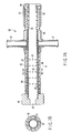
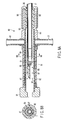
- the front-end plate 102 in the cleaning device according to the second embodiment is removed, the front-end opening of the cylindrical member 101 is opened, and the front-end opening is used as a drain port 141 to constitute a cleaning cover 142.
- the drain ports 125 in the cleaning device 100 according to the second embodiment are not disposed.
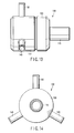
- a plurality of supply nozzles 143 are disposed in the cylindrical member 101 of the cleaning cover 142, and inner ends of the supply nozzles 143 form a jet ports (water supply ports) 145 in the inner surface of the cylindrical member 101.
- any of the respective jet ports 145 surrounds the cleaning region where the cleaning object is disposed in the cleaning cover 142, and the jet port is disposed so as to be directed to the cleaning region from the periphery.
- three supply nozzles 143 are disposed, and the supply nozzles 143 are arranged so that the water is equally radiated in three directions from the center of the cleaning cover 142.
- the high-pressure cleaning water is spouted toward the distal-end function portion 21 of the cleaning object disposed in the cleaning cover 104 via three jet ports 145. Moreover, the cleaning is possible in which the cleaning water is spouted from three peripheral directions. Therefore, even the strong dirt can be removed, and every corner can strongly be cleaned without any unevenness.
- the cleaning water which has overflowed in the cleaning cover 104 can be drained to the outside of the cleaning cover 104 from the drain port 141 which largely opens forwards.
- the other constitution is similar to that of the cleaning device according to the above-described embodiments.
- the cleaning device of the present invention for the medical instrument, especially the treatment portion which easily strongly becomes dirty can efficiently be cleaned.
Landscapes
- Health & Medical Sciences (AREA)
- Surgery (AREA)
- Life Sciences & Earth Sciences (AREA)
- Heart & Thoracic Surgery (AREA)
- Pathology (AREA)
- Oral & Maxillofacial Surgery (AREA)
- Engineering & Computer Science (AREA)
- Biomedical Technology (AREA)
- Nuclear Medicine, Radiotherapy & Molecular Imaging (AREA)
- Medical Informatics (AREA)
- Molecular Biology (AREA)
- Animal Behavior & Ethology (AREA)
- General Health & Medical Sciences (AREA)
- Public Health (AREA)
- Veterinary Medicine (AREA)
- Surgical Instruments (AREA)
Abstract
Description
Claims (9)
- A cleaning device which cleans a treatment portion (21) of a medical instrument (1), characterized by comprising:a cleaning cover (81) including a containing portion (88) which surrounds the treatment portion (21) and which contains the treatment portion (21), and an insertion opening (86) via which the treatment portion (21) is inserted into the containing portion (88);an engagement portion (92) which engages with the medical instrument (1) including the treatment portion (21) inserted in the containing portion (88) via the insertion opening (86) and which holds the medical instrument (1) in the cleaning cover (81);a water supply port (91) which is disposed in the cleaning cover (81) and which communicates with the containing portion (88) and which supplies cleaning water into the containing portion (88); anda drain port (90) which is disposed in the cleaning cover (81) and which communicates with the containing portion (88) and via which the cleaning water in the containing portion (88) is drained to the outside of the cleaning cover (81).
- The cleaning device for the medical instrument (1) according to claim 1, characterized in that the water supply port (91) is provided on an outer wall of the containing portion (88), and which further includes a water supply nozzle (87) which is formed in an inner wall of the containing portion (88) and which spouts the cleaning water toward the treatment portion (21) contained in the containing portion (88).
- The cleaning device for the medical instrument according to claim 1 or 2, characterized by further includes a plurality of water supply nozzles (87) which are formed in an inner wall of the containing portion and which spout the cleaning water toward the treatment portion (21) contained in the containing portion (88), and the water supply nozzles (87) are arranged over a whole periphery in a peripheral direction of an inner surface of the containing portion (88).
- The cleaning device for the medical instrument according to claim 3, characterized in that the containing portion (88) is constituted of two cylindrical members (61, 62) arranged coaxially and doubly, and
further includes a water supply channel (89) which is formed by a gap formed between both the cylindrical members (61, 62) and which connects the water supply port (91) to the water supply nozzle (87). - The cleaning device for the medical instrument according to claim 1, 2, or 3, characterized in that the cleaning cover (81) is formed of a transparent material via which the containing portion (88) able to be seen through.
- A cleaning device which cleans a treatment portion of a medical instrument, characterized by comprising:a cleaning cover (81) including a containing portion (88) which surrounds the treatment portion (21) and which can contain the treatment portion (21), and an insertion opening (86) via which the treatment portion (21) is inserted in the containing portion (88) ;an engagement portion (92) which engages with the medical instrument (1) including the treatment portion (21) inserted in the containing portion (88) via the insertion opening (86) and which holds the medical instrument (1) in the cleaning cover (81);a water supply port (91) which supplies cleaning water into the containing portion (88);a plurality of water supply nozzles (87) which are disposed in an inner wall of the containing portion (88) and which are arranged radially centering on an installation position middle of the treatment portion (21) contained in the containing portion (88);a water supply channel (89) which communicates the water supply nozzle (87) and the water supply port (91) and which supplies the cleaning water to the water supply nozzle (87); anda drain port (90) which is connected into the containing portion (88) and which drains the cleaning water of the containing portion (88) to the outside of the cleaning cover (81).
- The cleaning device for the medical instrument according to claim 6, characterized in that the cleaning cover (81) is formed of a transparent material via which the containing portion (88) can be seen through.
- A cleaning device which cleans a treatment portion (21) of a medical instrument (1), characterized by comprising:a cleaning cover (81) including a containing portion (88) which surrounds the treatment portion (21) and which contains the treatment portion (21), and an insertion opening (86) via which the treatment portion (21) is inserted in the containing portion (88);an engagement portion (92) which engages with the medical instrument (1) including the treatment portion (21) inserted in the containing portion (88) via the insertion opening (86);a water supply nozzle (87) which is disposed in an inner wall of the containing portion (88) and which opens toward the treatment portion (21) contained in the containing portion (88);a water supply port (91) which communicates with the water supply nozzle (87) and which supplies cleaning water into the containing portion (88); anda plurality of drain ports (90) which are arranged in the cleaning cover (81) and which communicates with the containing portion (88) and via which the cleaning water in the containing portion (88) is drained to the outside of the cleaning cover (81).
- The cleaning device for the medical instrument according to claim 8, characterized in that the cleaning cover (81) is formed of a transparent material via which the containing portion (88) able to be seen through.
Applications Claiming Priority (2)
| Application Number | Priority Date | Filing Date | Title |
|---|---|---|---|
| JP2002268730 | 2002-09-13 | ||
| JP2002268730A JP2004105283A (en) | 2002-09-13 | 2002-09-13 | Washing device for surgical treatment instrument |
Publications (3)
| Publication Number | Publication Date |
|---|---|
| EP1398004A2 true EP1398004A2 (en) | 2004-03-17 |
| EP1398004A3 EP1398004A3 (en) | 2004-12-08 |
| EP1398004B1 EP1398004B1 (en) | 2008-08-13 |
Family
ID=31884818
Family Applications (1)
| Application Number | Title | Priority Date | Filing Date |
|---|---|---|---|
| EP03020413A Expired - Lifetime EP1398004B1 (en) | 2002-09-13 | 2003-09-10 | Cleaning device for medical instrument |
Country Status (4)
| Country | Link |
|---|---|
| US (1) | US20040118440A1 (en) |
| EP (1) | EP1398004B1 (en) |
| JP (1) | JP2004105283A (en) |
| DE (1) | DE60322806D1 (en) |
Cited By (6)
| Publication number | Priority date | Publication date | Assignee | Title |
|---|---|---|---|---|
| DE102005048211A1 (en) * | 2005-09-29 | 2007-04-05 | Aesculap Ag & Co. Kg | Surgical storage for cleaning and storing of tubular surgical tools or instruments e.g. arthroscopic instruments, has rotatably stored cutting blades relative to each other, which are arranged on a tubular section |
| GB2435214A (en) * | 2006-01-31 | 2007-08-22 | Michael John Radley Young | Ultrasonic surgical tool having alignment means |
| EP1834600A1 (en) * | 2006-03-15 | 2007-09-19 | Karl Storz GmbH & Co. KG | Device for cleaning a flexible quill shaft for a medical instrument |
| EP1949868A1 (en) | 2007-01-26 | 2008-07-30 | International Steel Co. SpA | Washing device for medical instruments |
| EP1974687A1 (en) | 2007-03-30 | 2008-10-01 | Tyco Healthcare Group, LP | Surgical instrument debris collection system |
| EP2105099A1 (en) * | 2008-03-27 | 2009-09-30 | Olympus Medical Systems Corporation | Ultrasonic operating apparatus |
Families Citing this family (20)
| Publication number | Priority date | Publication date | Assignee | Title |
|---|---|---|---|---|
| US8388523B2 (en) | 2005-04-01 | 2013-03-05 | Welch Allyn, Inc. | Medical diagnostic instrument having portable illuminator |
| JP2009515561A (en) * | 2005-04-01 | 2009-04-16 | ウェルチ アレン インコーポレーテッド | Lighting assembly for use with colposcopic instruments |
| US8142352B2 (en) | 2006-04-03 | 2012-03-27 | Welch Allyn, Inc. | Vaginal speculum assembly having portable illuminator |
| JP2009028156A (en) * | 2007-07-25 | 2009-02-12 | Terumo Corp | Medical manipulator and cleaning method thereof |
| JP5042738B2 (en) * | 2007-07-30 | 2012-10-03 | テルモ株式会社 | Working mechanism and cleaning method of medical manipulator |
| DE102013108295B4 (en) * | 2013-08-01 | 2023-01-19 | Ferton Holding S.A. | cleaning device |
| JP6150672B2 (en) * | 2013-08-26 | 2017-06-21 | オリンパス株式会社 | Medical manipulator |
| SI24458A (en) * | 2013-09-18 | 2015-03-31 | Belimed Ag | Improved rotary washing assembly |
| US9216064B2 (en) * | 2014-05-02 | 2015-12-22 | David B. Geddis | System for cleaning robotic surgical instruments |
| US9808324B2 (en) * | 2014-06-12 | 2017-11-07 | Covidien Lp | Cleaning system for reprocessing medical devices |
| WO2015200702A1 (en) | 2014-06-27 | 2015-12-30 | Covidien Lp | Cleaning device for catheter and catheter including the same |
| US9532706B2 (en) | 2014-08-07 | 2017-01-03 | Welch Allyn, Inc. | Vaginal speculum with illuminator |
| US10314667B2 (en) * | 2015-03-25 | 2019-06-11 | Covidien Lp | Cleaning device for cleaning medical instrument |
| JP5843990B1 (en) * | 2015-04-27 | 2016-01-13 | クリーンケミカル株式会社 | Pre-cleaning kit for surgery support robot instrument |
| JP6393855B2 (en) * | 2016-08-26 | 2018-09-19 | オリンパス株式会社 | Cleaning instrument and endoscope system |
| US10814027B2 (en) | 2017-12-07 | 2020-10-27 | Asp Global Manufacturing Gmbh | Sterilization-assistance device |
| US10967084B2 (en) | 2017-12-15 | 2021-04-06 | Asp Global Manufacturing Gmbh | Flow restrictor |
| US10945808B2 (en) | 2018-04-23 | 2021-03-16 | Covidien Lp | Cleaning systems for reprocessing surgical instruments |
| JP2021527458A (en) | 2018-06-20 | 2021-10-14 | エイエスピー・グローバル・マニュファクチャリング・ゲーエムベーハー | Endoscope reprocessing device |
| US11986361B2 (en) * | 2020-11-17 | 2024-05-21 | Virginia Commonwealth University | Stent retriever cleaning devices and methods |
Family Cites Families (14)
| Publication number | Priority date | Publication date | Assignee | Title |
|---|---|---|---|---|
| JP2539827B2 (en) * | 1987-05-08 | 1996-10-02 | オリンパス光学工業株式会社 | Treatment tool cleaning tube |
| US5288467A (en) * | 1988-06-06 | 1994-02-22 | Hans Biermaier | Cleaning and disinfecting machine for medical equipment and instruments, anesthetic tubes, catheters, and endoscopes |
| GB9020559D0 (en) * | 1990-09-20 | 1990-10-31 | Keymed Medicals & Ind Equip | Cleaning and disinfecting medical instruments |
| US5476454A (en) * | 1992-02-11 | 1995-12-19 | Minntech Corporation | Balloon catheter lock adaptor for use with a resterilization system |
| US5279317A (en) * | 1993-02-26 | 1994-01-18 | Bowman Michael D | Endoscopic cannulated instrument flushing apparatus for forcing a cleaning solution through an endoscopic cannulated instrument for removal of gross debris |
| US5320119A (en) * | 1993-03-05 | 1994-06-14 | Tnco, Inc. | Surgical tools cleansing |
| DE4323816C2 (en) * | 1993-07-15 | 1996-02-08 | Siemens Ag | Method and device for intensive cleaning of medical, in particular dental, objects |
| JPH10305011A (en) * | 1995-10-31 | 1998-11-17 | Yasuo Iwaki | Endoscope treatment tool and endoscope cleaning / disinfection / drying method using it |
| JPH1085180A (en) * | 1996-09-12 | 1998-04-07 | Yuzuru Kawamura | Endoscope cleaning equipment |
| US6454871B1 (en) * | 1997-06-23 | 2002-09-24 | Princeton Trade & Technology, Inc. | Method of cleaning passageways using a mixed phase flow of gas and a liquid |
| JP2000217781A (en) * | 1999-02-02 | 2000-08-08 | Olympus Optical Co Ltd | Cleaning and disinfection equipment for medical instruments |
| JP2001120643A (en) * | 1999-10-28 | 2001-05-08 | Fuji Photo Optical Co Ltd | Endoscope ultrasonic cleaning equipment |
| JP4460787B2 (en) * | 2001-02-13 | 2010-05-12 | オリンパス株式会社 | Ultrasonic treatment device |
| US6874517B2 (en) * | 2003-05-28 | 2005-04-05 | Steris Inc. | Valve holding fixture for automated reprocessor |
-
2002
- 2002-09-13 JP JP2002268730A patent/JP2004105283A/en active Pending
-
2003
- 2003-09-10 DE DE60322806T patent/DE60322806D1/en not_active Expired - Lifetime
- 2003-09-10 EP EP03020413A patent/EP1398004B1/en not_active Expired - Lifetime
- 2003-09-12 US US10/661,898 patent/US20040118440A1/en not_active Abandoned
Cited By (10)
| Publication number | Priority date | Publication date | Assignee | Title |
|---|---|---|---|---|
| DE102005048211A1 (en) * | 2005-09-29 | 2007-04-05 | Aesculap Ag & Co. Kg | Surgical storage for cleaning and storing of tubular surgical tools or instruments e.g. arthroscopic instruments, has rotatably stored cutting blades relative to each other, which are arranged on a tubular section |
| DE102005048211B4 (en) * | 2005-09-29 | 2009-02-26 | Aesculap Ag | Surgical storage, surgical system and method of cleaning |
| GB2435214A (en) * | 2006-01-31 | 2007-08-22 | Michael John Radley Young | Ultrasonic surgical tool having alignment means |
| GB2435214B (en) * | 2006-01-31 | 2010-01-20 | Michael John Radley Young | Ultrasonic Cutting Tool |
| EP1834600A1 (en) * | 2006-03-15 | 2007-09-19 | Karl Storz GmbH & Co. KG | Device for cleaning a flexible quill shaft for a medical instrument |
| US8721806B2 (en) | 2006-03-15 | 2014-05-13 | Karl Storz Gmbh & Co. Kg | Device for cleaning a flexible hollow shaft of a medical instrument |
| EP1949868A1 (en) | 2007-01-26 | 2008-07-30 | International Steel Co. SpA | Washing device for medical instruments |
| EP1974687A1 (en) | 2007-03-30 | 2008-10-01 | Tyco Healthcare Group, LP | Surgical instrument debris collection system |
| US8734730B2 (en) | 2007-03-30 | 2014-05-27 | Covidien Lp | Surgical instrument debris collection system |
| EP2105099A1 (en) * | 2008-03-27 | 2009-09-30 | Olympus Medical Systems Corporation | Ultrasonic operating apparatus |
Also Published As
| Publication number | Publication date |
|---|---|
| US20040118440A1 (en) | 2004-06-24 |
| EP1398004A3 (en) | 2004-12-08 |
| DE60322806D1 (en) | 2008-09-25 |
| JP2004105283A (en) | 2004-04-08 |
| EP1398004B1 (en) | 2008-08-13 |
Similar Documents
| Publication | Publication Date | Title |
|---|---|---|
| EP1398004B1 (en) | Cleaning device for medical instrument | |
| CN111789565B (en) | endoscope | |
| JP2002112963A (en) | Method and apparatus for cleaning a pipe in a medical device | |
| JP2004000336A (en) | Ultrasonic treatment apparatus | |
| JPS62275440A (en) | Ultrasonic endoscope | |
| JPH04312437A (en) | Pipe cleaning device | |
| JP4395603B2 (en) | Ultrasound endoscope | |
| JPH06154155A (en) | Endoscope | |
| US7475697B2 (en) | Cleaning device for medical instruments | |
| JPH10127567A (en) | Endoscope | |
| JP2010057728A (en) | Piping connection adapter | |
| WO2018179758A1 (en) | Ultrasonic endoscope | |
| JP4087937B2 (en) | Endoscope | |
| US20030191390A1 (en) | Ultrasonic treatment apparatus | |
| JPH0889504A (en) | Intracorporeal ultrasound probe | |
| JP7057269B2 (en) | Coated endoscopy probe | |
| JPH074371B2 (en) | Ultrasound endoscope | |
| JP4643669B2 (en) | Ultrasound endoscope | |
| US20180116495A1 (en) | High-pressure endoscope cleaning device | |
| JP4248909B2 (en) | Ultrasound endoscope | |
| JP3368793B2 (en) | Separate conduit endoscope device | |
| JPH08224207A (en) | Endoscope device | |
| JPH08256978A (en) | Endoscope device | |
| JP4398391B2 (en) | Ultrasonic treatment device | |
| JP3183067B2 (en) | Fluid supply / discharge device for ultrasonic endoscope |
Legal Events
| Date | Code | Title | Description |
|---|---|---|---|
| PUAI | Public reference made under article 153(3) epc to a published international application that has entered the european phase |
Free format text: ORIGINAL CODE: 0009012 |
|
| AK | Designated contracting states |
Kind code of ref document: A2 Designated state(s): AT BE BG CH CY CZ DE DK EE ES FI FR GB GR HU IE IT LI LU MC NL PT RO SE SI SK TR |
|
| AX | Request for extension of the european patent |
Extension state: AL LT LV MK |
|
| PUAL | Search report despatched |
Free format text: ORIGINAL CODE: 0009013 |
|
| AK | Designated contracting states |
Kind code of ref document: A3 Designated state(s): AT BE BG CH CY CZ DE DK EE ES FI FR GB GR HU IE IT LI LU MC NL PT RO SE SI SK TR |
|
| AX | Request for extension of the european patent |
Extension state: AL LT LV MK |
|
| 17P | Request for examination filed |
Effective date: 20050524 |
|
| RAP1 | Party data changed (applicant data changed or rights of an application transferred) |
Owner name: OLYMPUS CORPORATION |
|
| AKX | Designation fees paid |
Designated state(s): DE FR GB |
|
| GRAP | Despatch of communication of intention to grant a patent |
Free format text: ORIGINAL CODE: EPIDOSNIGR1 |
|
| GRAS | Grant fee paid |
Free format text: ORIGINAL CODE: EPIDOSNIGR3 |
|
| GRAA | (expected) grant |
Free format text: ORIGINAL CODE: 0009210 |
|
| AK | Designated contracting states |
Kind code of ref document: B1 Designated state(s): DE FR GB |
|
| REG | Reference to a national code |
Ref country code: GB Ref legal event code: FG4D |
|
| REF | Corresponds to: |
Ref document number: 60322806 Country of ref document: DE Date of ref document: 20080925 Kind code of ref document: P |
|
| PLBE | No opposition filed within time limit |
Free format text: ORIGINAL CODE: 0009261 |
|
| STAA | Information on the status of an ep patent application or granted ep patent |
Free format text: STATUS: NO OPPOSITION FILED WITHIN TIME LIMIT |
|
| 26N | No opposition filed |
Effective date: 20090514 |
|
| PGFP | Annual fee paid to national office [announced via postgrant information from national office to epo] |
Ref country code: FR Payment date: 20100921 Year of fee payment: 8 |
|
| PGFP | Annual fee paid to national office [announced via postgrant information from national office to epo] |
Ref country code: GB Payment date: 20100908 Year of fee payment: 8 |
|
| GBPC | Gb: european patent ceased through non-payment of renewal fee |
Effective date: 20110910 |
|
| REG | Reference to a national code |
Ref country code: FR Ref legal event code: ST Effective date: 20120531 |
|
| PG25 | Lapsed in a contracting state [announced via postgrant information from national office to epo] |
Ref country code: GB Free format text: LAPSE BECAUSE OF NON-PAYMENT OF DUE FEES Effective date: 20110910 Ref country code: FR Free format text: LAPSE BECAUSE OF NON-PAYMENT OF DUE FEES Effective date: 20110930 |
|
| PGFP | Annual fee paid to national office [announced via postgrant information from national office to epo] |
Ref country code: DE Payment date: 20190918 Year of fee payment: 17 |
|
| REG | Reference to a national code |
Ref country code: DE Ref legal event code: R119 Ref document number: 60322806 Country of ref document: DE |
|
| PG25 | Lapsed in a contracting state [announced via postgrant information from national office to epo] |
Ref country code: DE Free format text: LAPSE BECAUSE OF NON-PAYMENT OF DUE FEES Effective date: 20210401 |