EP1397314B1 - Quench station and method for quenching formed glass sheets - Google Patents
Quench station and method for quenching formed glass sheets Download PDFInfo
- Publication number
- EP1397314B1 EP1397314B1 EP02780814A EP02780814A EP1397314B1 EP 1397314 B1 EP1397314 B1 EP 1397314B1 EP 02780814 A EP02780814 A EP 02780814A EP 02780814 A EP02780814 A EP 02780814A EP 1397314 B1 EP1397314 B1 EP 1397314B1
- Authority
- EP
- European Patent Office
- Prior art keywords
- quench
- quenching
- head assemblies
- shuttle
- glass sheets
- Prior art date
- Legal status (The legal status is an assumption and is not a legal conclusion. Google has not performed a legal analysis and makes no representation as to the accuracy of the status listed.)
- Expired - Lifetime
Links
Images


Classifications
-
- C—CHEMISTRY; METALLURGY
- C03—GLASS; MINERAL OR SLAG WOOL
- C03B—MANUFACTURE, SHAPING, OR SUPPLEMENTARY PROCESSES
- C03B27/00—Tempering or quenching glass products
- C03B27/04—Tempering or quenching glass products using gas
- C03B27/044—Tempering or quenching glass products using gas for flat or bent glass sheets being in a horizontal position
- C03B27/0442—Tempering or quenching glass products using gas for flat or bent glass sheets being in a horizontal position for bent glass sheets
- C03B27/0447—Tempering or quenching glass products using gas for flat or bent glass sheets being in a horizontal position for bent glass sheets the quench unit being variably adaptable to the bend of the sheet
-
- C—CHEMISTRY; METALLURGY
- C03—GLASS; MINERAL OR SLAG WOOL
- C03B—MANUFACTURE, SHAPING, OR SUPPLEMENTARY PROCESSES
- C03B27/00—Tempering or quenching glass products
- C03B27/04—Tempering or quenching glass products using gas
- C03B27/0417—Controlling or regulating for flat or bent glass sheets
-
- C—CHEMISTRY; METALLURGY
- C03—GLASS; MINERAL OR SLAG WOOL
- C03B—MANUFACTURE, SHAPING, OR SUPPLEMENTARY PROCESSES
- C03B35/00—Transporting of glass products during their manufacture, e.g. hot glass lenses, prisms
- C03B35/14—Transporting hot glass sheets or ribbons, e.g. by heat-resistant conveyor belts or bands
- C03B35/20—Transporting hot glass sheets or ribbons, e.g. by heat-resistant conveyor belts or bands by gripping tongs or supporting frames
- C03B35/202—Transporting hot glass sheets or ribbons, e.g. by heat-resistant conveyor belts or bands by gripping tongs or supporting frames by supporting frames
Definitions
- This invention relates to a quench station and a method for quenching formed glass sheets in a manner that can reduce cycle time and thus increase production.
- Systems for forming glass sheets by heating and then quenching the glass sheets to provide toughening have cycle times whose shortening can be limited by the length of time required to perform the quenching.
- the quenching is performed by quenching gas that is directed to opposite surfaces of the formed glass sheet to provide a temperature differential between the surfaces and the glass center. That temperature differential must remain throughout the cooling until reaching ambient temperature or the glass will not be toughened by providing compression of its surfaces and tensioning of its center.
- United States Patent 4,361,432 McMaster et al discloses glass sheet quenching between lower and upper quench heads with the formed glass sheet on an open center ring and, upon completion of the quenching, the downwardly directed quenching gas from the upper quench head is terminated to lift the glass sheet upwardly from the open center ring against the upper quench head to permit the ring to be moved to start another cycle.
- a delivery ring is moved under the formed glass sheet and the downwardly directed gas is again supplied to deposit the glass sheet on the delivery ring for delivery when the next formed glass sheet is moved to between the lower and upper quench heads for the quenching.
- One object of the present invention is to provide an improved quench station for quenching formed glass sheets.
- the quench station for quenching formed glass sheets in accordance with the invention includes a first quench section having lower and upper quench head assemblies for respectively supplying upwardly and downwardly directed quenching gas to a formed glass sheet therebeween to provide partial quenching of the glass sheet.
- a first quench section having lower and upper quench head assemblies for respectively supplying upwardly and downwardly directed quenching gas to a formed glass sheet therebeween to provide partial quenching of the glass sheet.
- Such partial quenching is insufficient without further forced cooling in addition to natural convection to prevent the loss of the glass temperature differentials that toughens the glass upon finally cooling to ambient temperature.
- a second quench section of the quench station has lower and upper quench head assemblies for respectively supplying upwardly and downwardly directed quenching gas to the partially quenched glass sheet upon being received therebetween to complete the quenching of the glass sheet.
- a shuttle of the quench station is movable in a transfer direction simultaneously with respect to a forming station where the glass sheet is formed, the first quench section and the second quench section to provide glass sheet transfer.
- the shuttle has three glass positions so as to be capable of simultaneously transferring three glass sheets upon each movement in the transfer direction, preferably by a shuttle member that connects the three glass positions and that is moved by an actuator. Three glass sheets are thus simultaneously moved from the forming station to the first quench section, from the first quench section to the second quench section, and from the second quench section for delivery.
- a control of the quench station supplies quenching gas to the upper and lower quench sections of the first and second quench sections to force the glass sheets upwardly from the shuttle against the upper quench head assemblies and permit movement of the shuttle in the opposite direction to the transfer direction in preparation from the next cycle.
- the construction of the quench station includes a framework, and the lower and upper quench head assemblies of each quench section each includes a plurality of quench heads through which pressurized gas is delivered.
- the quench heads of each quench head assembly are adjustable with respect to each other to permit quenching of different shapes of formed glass sheets.
- the lower and upper quench head assemblies respectively include lower and upper templates mounted on the framework to position the quench heads thereof in the proper position for the glass sheet shape to be quenched.
- Adjusters of the quench station adjust the locations of the templates on the framework to properly position the quench heads. Clamps secure the templates with respect to the framework, with the clamping being provided after the adjustment provided the adjusters.
- the lower and upper quench head assemblies respectively include lower and upper linkages for connecting their quench heads.
- Lower and upper quench head actuators respectively extend between the framework and the lower and upper quench head assemblies to provide adjusting movement of the quench heads under the control of the linkages in preparation for positioning the quench head assemblies by the lower and upper templates.
- Each of the upper quench head assemblies includes thermally insulative stops against which the glass sheets are forced upwardly by the upwardly directed quenching gases during the cyclical operation of the quench station.
- Another object of the present invention is to provide an improved method for quenching formed glass sheets.
- the method for quenching formed glass sheets in accordance with the invention is performed by moving a first formed glass sheet on a shuttle from a forming station to a first quench section having lower and upper quench head assemblies for respectively supplying upwardly and downwardly directed quenching gas to provide partial quenching thereof which is insufficient without further forced cooling in addition to natural convection to prevent loss of the glass temperature differential that toughens the glass upon finally cooling to ambient temperature.
- a second partially quenched formed glass sheet is moved on the shuttle from the first quench section to a second quench section having lower and upper quench head assemblies for respectively supplying upwardly and downwardly directed quenching gas to the partially quenched glass sheet upon being received therebetween to complete the quenching of the second glass sheet.
- a third fully quenched glass sheet is moved from the second quench station for a final cooling to ambient temperature, with the first, second and third glass sheets preferably moved on a shuttle member of the shuttle by an actuator.
- the flow of the quenching gas from the lower and upper quench head assemblies of the first and second quench sections is controlled to move the formed glass sheet upwardly from the shuttle after movement thereto on the shuttle and thereby permits reverse movement of the shuttle in preparation for another cycle. Subsequently the flow of the quenching gas from the lower and upper quench head assemblies of the first and second is controlled to move the formed glass sheets downwardly onto the shuttle to permit another cycle of transferring three formed glass sheets from the forming station to the first quench section, from the first quench section to the second quench section, and from the second quench section for final cooling.
- the lower and upper quench head assemblies are respectively positioned by lower and upper templates, and the lower and upper templates are adjusted with respect to a framework of the quench sections and are clamped with respect to the framework to position the lower and upper quench head assemblies. Furthermore, the quench heads of the lower and upper quench head assemblies are respectively connected by lower and upper linkages and are moved by associated actuators for positioning in preparation for use.
- the glass sheets are forced upwardly against thermally insulative stops of the upper quench head assemblies.
- a glass sheet forming and quenching system generally indicated by 10 includes a furnace 12 for heating glass sheets, a forming station 14 for forming the heated glass sheets, and a quench station 16 that is constructed in accordance with the invention to provide the quenching method thereof as is hereinafter more fully described.
- the construction of the quench station 16 and its method of operation will be described in an integrated manner to facilitate an understanding of all aspects of the invention.
- the furnace 12 of the system includes a conveyor 18 on which glass sheets G are heated within a heating chamber of the furnace to a sufficiently high temperature to permit forming and quenching of the glass.
- the heated glass sheets G are transferred or conveyed in any suitable manner to the forming station 14 where forming apparatus 20 forms each heated glass sheet from a flat shape to a curved shape.
- the heated glass sheet is supported as illustrated by an upper vacuum mold 22 in preparation for being transferred to the quench station 16 which, as mentioned above, is constructed in accordance with the present invention.
- the quench station 16 of the invention as illustrated in Figure 1 includes first and second quench sections 24 and 26, a shuttle 28 that simultaneously provides movement of three formed sheets G 1 , G 2 , and G 3 through the quench station as is hereinafter more fully described.
- the quench station also includes a control 30 that supplies quenching gas in a controlled manner which during cyclical operation moves the glass sheets upwardly from and subsequently downwardly back onto the shuttle 28 upon passage through the quench station.
- the formed glass sheets normally will have curvature in a transverse direction to the direction of conveyance through the quench station 26 and may also have curvature along the direction of conveyance as illustrated.
- the first quench section 24 has lower and upper quench head assemblies 32 and 34 for respectively supplying upwardly and downwardly directed quench gas to a formed glass sheet therebetween to provide partial quenching of the formed glass sheet.
- the quenching provided by the first quench section 24 is insufficient without further forced cooling in addition to natural convention to prevent loss of the glass temperature differential that toughens the glass upon final cooiing to ambient temperature, either by heat strengthening or more rapid cooling that provides tempering.
- the second quench section 26 of the quench station also has lower and upper quench head assemblies 32 and 34 for respectively supplying upwardly and downwardly directed quenching gas to the partially quenched glass sheet upon being received therebetween during the shuttle transfer cycle described below.
- This quenching in the second quench station 26 completes the quenching of the glass sheet to provide heat strengthening or tempering as required by the particular manufacturing job being processed.
- the quench station Downstream to the right of the second quench section 26, the quench station includes an after-cooling section 36 having an upper stop 38 against which a quenched glass sheet is supported during the transfer cycle in preparation for being transferred to an unshown after-cooling conveyor and ultimate delivery from the system.
- the shuttle 28 illustrated in Figure 1 is movable along a transfer direction that corresponds with the direction conveyance C toward the right through the system and is moved by an actuator 40 so as to be simultaneously moved with respect to the forming station 14 where each glass sheet is formed, the first quench section 24, and the second quench section 26 as well as the after-cooling section 36.
- the shuttle 28 has three positions each of which includes an associated open ring 42, 44 and 46 for respectively supporting and transferring three glass sheets during each movement toward the right.
- the preferred construction of the shuttle 28 includes a shuttle member 29 that connects the open rings 42, 44 and 46 such that operation of the single actuator 40 simultaneously moves the one glass sheet G 1 from the forming station 14 to the first quench section 24 as shown, the second glass sheet G 2 from the first quench section 24 to the second quench section 26 as shown, and the third glass sheet G 3 from the second quench section 26 to the after-cooling section 36 for transfer to the unshown after-cooling conveyor and ultimate delivery as previously mentioned.
- the gas quench control 30 includes a source 48 of pressurized quenching gas that is delivered to the quench station through a main supply conduit 50.
- a valve controller 52 controls valves 54 and 56 that respectively control flow through delivery conduits 58 and 60 to the lower and upper quench head assemblies 32 and 34 of the first quench section 24.
- Valve controller 52 also controls valves 62 and 64 that control the flow of quenching gas through conduits 66 and 68 that supply the lower and upper quench head assemblies 32 and 34 of the second quench station 26.
- the valve controller 52 controls a valve 70 that controls the flow of quenching gas 72 to a lower blowup plenum 74 that supplies upwardly directed quench gas at the after-cooling station 36.
- Each cycle of operation of the shuttle 28 illustrated in Figure 1 is performed by moving the shuttle from the left toward the right to the position illustrated to transfer three glass sheets, one glass sheet G 1 from the forming station 14 to the first quench section 24, the second glass sheet G 2 from the first quench section 24 to the second quench section 26, and the third glass sheet G 3 from the second quench section 26 to the after-cooling section 36.
- the quenching gas is supplied under the operation of control 30 to the first and second formed glass sheets G 1 and G 2 for a sufficient time to provide the partial quenching of the first glass sheet G 1 and to complete the quenching of the second glass sheet G 2 .
- the time involved for such quenching will depend upon the glass thickness but will normally be about 11 ⁇ 2 to 2 seconds.
- the control 30 then provides a change in the force applied to the glass sheets to provide lifting thereof upwardly off of the associated shuttle rings 42, 44 and 46.
- the glass sheet G 1 is moved upwardly against the upper quench head assembly 34 of the first quench section 24
- the second glass sheet G 2 is moved upwardly against the upper quench head assembly 34 of the second quench section 26
- the third glass sheet G 3 is moved upwardly against the stop 38 of the after-cooling section 36.
- the quenching proceeds at this time with the lower quench head assemblies 32 of both the first and second quench sections 24 and 26 continuing to supply upwardly directed quenching gas and with the upper quench head assemblies 34 continuing to supply downwardly directed quenching gas. Simultaneously, the movement of the shuttle 28 back toward the left permits commencement of another cycle as the glass sheets progress through the quench station from the left toward the right with three being moved during each shuttle movement toward the right.
- the quenching gas supplied to the first and second quench sections 24 and 26 is changed by the control 30 to release the formed glass sheets from their associated upper quench head assemblies 34 to allow the glass sheet thereof to respectively drop downwardly onto the shuttle rings 44 and 46 in preparation for respective movement from the first quench section 24 to the second quench section 26 and for movement from the second quench section 26 to the after-cooling section 36.
- the change in the gas flows to lift the glass sheets can be done by: (1) increasing the upward gas flow; (2) decreasing the downward gas flow; or (3) both increasing the upward gas flow and decreasing the downward gas flow.
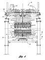
- the lower and upper blast head assemblies 32 and 34 each include a plurality of quench heads 76 and 78, respectively, through which quenching gas is supplied upwardly and downwardly through openings in the opposed faces of the quench heads. Furthermore, as shown in Figure 1 , the upstream ends of the lower and upper quench heads 76 and 78 are respectively connected by lower and upper linkages 80 and 82 and are positioned by lower and upper templates 84 and 86. Likewise, the downstream ends of the lower and upper quench heads 76 and 78 of the second quench section 26 are also respectively connected by lower and upper linkages 80 and 82 and are positioned by lower and upper templates 84 and 86.
- lower and upper quench heads 76 and 78 of the lower and upper quench head assemblies 32 and 34 of the first and second quench section 24 and 26 are fluidly isolated from each other, their respective downstream and upstream ends have mechanical lower and upper connectors 88 and 90 so as to be movable and positioned with each other in association with the lower and upper linkages 80 and 82 and the lower and upper templates 84 and 86.
- the quench station includes a framework 92 including vertical posts 94 and horizontal beams 96 on which the lower and upper quench head assemblies 32 and 34 are mounted.
- Both the lower and upper linkages 80 and 82 of the lower and upper quench head assemblies have a construction best illustrated in Figure 4 by the lower linkage which includes lower and upper link rows 98 and 99 that each include links 100 having pivotal connections 101 to the associated quench heads and to the adjacent links to provide a saw tooth shape that controls the angular positioning of the quench heads with respect to each other so the lower and upper quench heads oppose each other.
- the quench heads of the lower and upper quench head assemblies 32 and 34 are thus adjustable with respect to each other to permit quenching of different shapes of formed glass sheets.
- the lower and upper templates 84 and 86 have upwardly facing positioning notches 102 and 104 that receive lower and upper positioners 106 and 108 on the adjacent ends of the lower and upper quench heads 76 and 78 to provide proper positioning of the quench heads with the associated linkages providing the proper angular location of the lower and upper quench heads with respect to each other.
- the quenching gas supply ducts 50 a and 50 b supply pressurized quenching gas to flexible lower and upper conduits 58 and 60 that respectively supply quenching gas to the lower and upper quench heads 76 and 78 of the lower and upper quench head assemblies 32 and 34.
- lower and upper linkages 80 and 82 of the lower and upper quench head assemblies 32 and 34 as mentioned above ensure that the opposed faces of the lower and upper quench heads 76 and 78 are aligned with each other in order to provide uniform distribution of quenching gas to the quenched glass sheet G therebetween.
- lower and upper adjusters 110 and 112 respectively associated with the lower and upper templates 84 and 86 provide the proper positioning of the templates on the framework 92 in order to provide the proper positioning of the lower and upper quench heads 76 and 78 in association with the angular positioning provided by the lower and upper linkages.
- Each adjuster 110 and 112 as shown in Figures 6 and 7 includes a threaded adjusting member 114 that is received by a threaded member 116 on the associated template and has a lower end engaged with a support lug 118 on the framework 92 such that threading of the adjusting member provides upward and downward movement of the template to the proper location.
- a lock nut 120 on the adjusting member 114 is threaded against the template mounted member 116 to secure the adjusted position.
- lower and upper clamps 122 and 124 respectively associated with the lower and upper templates 84 and 86 provide clamping of the templates to the framework 92 after the adjustment provided by the lower and upper adjusters 110 and 112 as described above.
- the lower and upper clamps 122 and 124 include clamp members 126 that are operated by clamp actuators 128 in any conventional manner to clamp the associated template against the framework 92 and prevent any movement thereof after the adjustment of the templates to the proper position.
- Clamp connectors 130 of each clamp extend from the clamp member 126 to the clamp actuator 128 and are received within downwardly opening notches 132 ( Figure 3 ) in the lower side of the associated template so as to permit the upward and downward adjusting movement as necessary until the template is in the proper position for the clamping.
- the lower and upper quench head assemblies include lower and upper actuators 134 and 136 that extend between the framework 92 and the lower and upper quench head assemblies 32 and 34. More specifically, each of the lower and upper quench head assemblies 32 and 34 has a center quench head 76, 78 that is fixedly positioned while the other quench heads are movable under the control of the lower and upper linkages previously described. The movement of the quench head assemblies for positioning by the templates as previously described prior to adjustment by the adjusters that were also previously described is initially provided by the lower and upper actuators 134 and 136.
- the lower actuators 134 have lower ends that are mounted on lower horizontal beams 96 and extend upwardly for connection to the lower quench head assembly 32 with some of the actuators having connections through links 138 and others having pivotal connections 140 connected directly to the associated lower quench heads 78.
- the lower actuators 134 are extendible to move the lower quench heads upwardly as required with the associated lower linkage 80 providing control of the angular position of the quench heads as they are moved.
- the upper actuators 136 illustrated in Figures 4 and 5 are mounted on upper horizontal beams 96 of the framework 92 and have connections 142 extending downwardly to a pair of links 144 that are connected to an adjacent pair of the upper quench heads 78. These upper actuators 136 move the upper quench heads 78 under the control of these upper linkages which provide the proper angular positioning so as to oppose the lower quench heads.
- the upper quench head assembly 34 includes thermally insulative stops 146 against which the glass sheets are forced upwardly by the quenching gas during the transferring operation as previously described. These thermally insulative stops 46 position the glass sheet and have sufficiently low thermal conductivity so as not to provide excessive conductive cooling thereof that would disrupt the uniformity in the glass cooling.
- the quench station framework 92 includes an upper frame 148 that supports each upper quench head assembly 34 and has a motor driven ball screw mechanism 150 for lifting the upper frame and the upper quench head assemblies to allow broken glass removal as well as maintenance and repair.
Landscapes
- Chemical & Material Sciences (AREA)
- Engineering & Computer Science (AREA)
- Materials Engineering (AREA)
- Organic Chemistry (AREA)
- Physics & Mathematics (AREA)
- Thermal Sciences (AREA)
- Re-Forming, After-Treatment, Cutting And Transporting Of Glass Products (AREA)
- Glass Compositions (AREA)
Description
- This invention relates to a quench station and a method for quenching formed glass sheets in a manner that can reduce cycle time and thus increase production.
- Systems for forming glass sheets by heating and then quenching the glass sheets to provide toughening have cycle times whose shortening can be limited by the length of time required to perform the quenching. The quenching is performed by quenching gas that is directed to opposite surfaces of the formed glass sheet to provide a temperature differential between the surfaces and the glass center. That temperature differential must remain throughout the cooling until reaching ambient temperature or the glass will not be toughened by providing compression of its surfaces and tensioning of its center.
- United States Patent
4,361,432 McMaster et al . discloses glass sheet quenching between lower and upper quench heads with the formed glass sheet on an open center ring and, upon completion of the quenching, the downwardly directed quenching gas from the upper quench head is terminated to lift the glass sheet upwardly from the open center ring against the upper quench head to permit the ring to be moved to start another cycle. A delivery ring is moved under the formed glass sheet and the downwardly directed gas is again supplied to deposit the glass sheet on the delivery ring for delivery when the next formed glass sheet is moved to between the lower and upper quench heads for the quenching. - One object of the present invention is to provide an improved quench station for quenching formed glass sheets.
- The object is solved by the quench station of
claim 1. - In carrying out the above object, the quench station for quenching formed glass sheets in accordance with the invention includes a first quench section having lower and upper quench head assemblies for respectively supplying upwardly and downwardly directed quenching gas to a formed glass sheet therebeween to provide partial quenching of the glass sheet. Such partial quenching is insufficient without further forced cooling in addition to natural convection to prevent the loss of the glass temperature differentials that toughens the glass upon finally cooling to ambient temperature. A second quench section of the quench station has lower and upper quench head assemblies for respectively supplying upwardly and downwardly directed quenching gas to the partially quenched glass sheet upon being received therebetween to complete the quenching of the glass sheet. A shuttle of the quench station is movable in a transfer direction simultaneously with respect to a forming station where the glass sheet is formed, the first quench section and the second quench section to provide glass sheet transfer. The shuttle has three glass positions so as to be capable of simultaneously transferring three glass sheets upon each movement in the transfer direction, preferably by a shuttle member that connects the three glass positions and that is moved by an actuator. Three glass sheets are thus simultaneously moved from the forming station to the first quench section, from the first quench section to the second quench section, and from the second quench section for delivery. A control of the quench station supplies quenching gas to the upper and lower quench sections of the first and second quench sections to force the glass sheets upwardly from the shuttle against the upper quench head assemblies and permit movement of the shuttle in the opposite direction to the transfer direction in preparation from the next cycle.
- The construction of the quench station includes a framework, and the lower and upper quench head assemblies of each quench section each includes a plurality of quench heads through which pressurized gas is delivered. The quench heads of each quench head assembly are adjustable with respect to each other to permit quenching of different shapes of formed glass sheets. The lower and upper quench head assemblies respectively include lower and upper templates mounted on the framework to position the quench heads thereof in the proper position for the glass sheet shape to be quenched. Adjusters of the quench station adjust the locations of the templates on the framework to properly position the quench heads. Clamps secure the templates with respect to the framework, with the clamping being provided after the adjustment provided the adjusters.
- The lower and upper quench head assemblies respectively include lower and upper linkages for connecting their quench heads. Lower and upper quench head actuators respectively extend between the framework and the lower and upper quench head assemblies to provide adjusting movement of the quench heads under the control of the linkages in preparation for positioning the quench head assemblies by the lower and upper templates.
- Each of the upper quench head assemblies includes thermally insulative stops against which the glass sheets are forced upwardly by the upwardly directed quenching gases during the cyclical operation of the quench station.
- Another object of the present invention is to provide an improved method for quenching formed glass sheets.
- This object is solved by the method according to claim 9.
- In carrying out the immediately preceding object, the method for quenching formed glass sheets in accordance with the invention is performed by moving a first formed glass sheet on a shuttle from a forming station to a first quench section having lower and upper quench head assemblies for respectively supplying upwardly and downwardly directed quenching gas to provide partial quenching thereof which is insufficient without further forced cooling in addition to natural convection to prevent loss of the glass temperature differential that toughens the glass upon finally cooling to ambient temperature. Simultaneously with the movement of the first formed glass sheet, a second partially quenched formed glass sheet is moved on the shuttle from the first quench section to a second quench section having lower and upper quench head assemblies for respectively supplying upwardly and downwardly directed quenching gas to the partially quenched glass sheet upon being received therebetween to complete the quenching of the second glass sheet. Simultaneously with the movement of the first and second glass sheets a third fully quenched glass sheet is moved from the second quench station for a final cooling to ambient temperature, with the first, second and third glass sheets preferably moved on a shuttle member of the shuttle by an actuator. The flow of the quenching gas from the lower and upper quench head assemblies of the first and second quench sections is controlled to move the formed glass sheet upwardly from the shuttle after movement thereto on the shuttle and thereby permits reverse movement of the shuttle in preparation for another cycle. Subsequently the flow of the quenching gas from the lower and upper quench head assemblies of the first and second is controlled to move the formed glass sheets downwardly onto the shuttle to permit another cycle of transferring three formed glass sheets from the forming station to the first quench section, from the first quench section to the second quench section, and from the second quench section for final cooling.
- In performing the quenching method, the lower and upper quench head assemblies are respectively positioned by lower and upper templates, and the lower and upper templates are adjusted with respect to a framework of the quench sections and are clamped with respect to the framework to position the lower and upper quench head assemblies. Furthermore, the quench heads of the lower and upper quench head assemblies are respectively connected by lower and upper linkages and are moved by associated actuators for positioning in preparation for use.
- During the quenching, the glass sheets are forced upwardly against thermally insulative stops of the upper quench head assemblies.
- The objects, features and advantages of the present invention are readily apparent from the following detailed description of the preferred embodiment when taken in connection with the accompanying drawings.
-
-
FIGURE 1 is a schematic side elevational view of a glass sheet processing system including a quench station constructed in accordance with the invention to perform the quenching method of the invention. -
FIGURE 2 is a cross sectional view taken through the quench station along the direction of line 2-2 inFigure 1 to illustrate lower and upper quench head assemblies that respectively provide upwardly and downwardly directed quenching gas to quench a formed glass sheet therebetween. -
FIGURE 3 is an enlarged view of a portion ofFigure 2 to further illustrate the lower and upper quench head assemblies and lower and upper templates that provide positioning of quench heads of each quench head assembly. -
FIGURE 4 is a sectional view taken through the quench station generally in the same direction asFigure 2 but at a different location to illustrate lower and upper linkages that provide connection between the quench heads of the lower and upper quench head assemblies. -
FIGURE 5 is a sectional view taken in the same direction asFigure 4 but at a different location to illustrate the manner in which actuators moves the quench heads of the lower and upper quench head assemblies in preparation for positioning thereof by the lower and upper templates illustrated inFigures 2 and3 . -
FIGURE 6 is a view taken along the direction of line 6-6 inFigure 3 to illustrate the manner in which the upper template is positioned by an adjuster and clamp to a framework of the quench station. -
FIGURE 7 is a view taken along the direction of line 7-7 inFigure 3 to illustrate the manner in which the lower template is positioned by an adjuster and secured by a clamp to the quench station framework. - With reference to
Figure 1 , a glass sheet forming and quenching system generally indicated by 10 includes afurnace 12 for heating glass sheets, a formingstation 14 for forming the heated glass sheets, and aquench station 16 that is constructed in accordance with the invention to provide the quenching method thereof as is hereinafter more fully described. The construction of thequench station 16 and its method of operation will be described in an integrated manner to facilitate an understanding of all aspects of the invention. - With continuing reference to
Figure 1 , thefurnace 12 of the system includes aconveyor 18 on which glass sheets G are heated within a heating chamber of the furnace to a sufficiently high temperature to permit forming and quenching of the glass. After the heating, the heated glass sheets G are transferred or conveyed in any suitable manner to the formingstation 14 where formingapparatus 20 forms each heated glass sheet from a flat shape to a curved shape. After the forming, the heated glass sheet is supported as illustrated by anupper vacuum mold 22 in preparation for being transferred to thequench station 16 which, as mentioned above, is constructed in accordance with the present invention. - The
quench station 16 of the invention as illustrated inFigure 1 includes first andsecond quench sections shuttle 28 that simultaneously provides movement of three formed sheets G1, G2, and G3 through the quench station as is hereinafter more fully described. In addition, the quench station also includes acontrol 30 that supplies quenching gas in a controlled manner which during cyclical operation moves the glass sheets upwardly from and subsequently downwardly back onto theshuttle 28 upon passage through the quench station. It should be noted that the formed glass sheets normally will have curvature in a transverse direction to the direction of conveyance through thequench station 26 and may also have curvature along the direction of conveyance as illustrated. - As illustrated by
Figures 1 and2 , thefirst quench section 24 has lower and upperquench head assemblies first quench section 24 is insufficient without further forced cooling in addition to natural convention to prevent loss of the glass temperature differential that toughens the glass upon final cooiing to ambient temperature, either by heat strengthening or more rapid cooling that provides tempering. Thesecond quench section 26 of the quench station also has lower and upperquench head assemblies second quench station 26 completes the quenching of the glass sheet to provide heat strengthening or tempering as required by the particular manufacturing job being processed. Downstream to the right of thesecond quench section 26, the quench station includes an after-cooling section 36 having anupper stop 38 against which a quenched glass sheet is supported during the transfer cycle in preparation for being transferred to an unshown after-cooling conveyor and ultimate delivery from the system. - The
shuttle 28 illustrated inFigure 1 is movable along a transfer direction that corresponds with the direction conveyance C toward the right through the system and is moved by anactuator 40 so as to be simultaneously moved with respect to the formingstation 14 where each glass sheet is formed, thefirst quench section 24, and thesecond quench section 26 as well as the after-cooling section 36. Theshuttle 28 has three positions each of which includes an associatedopen ring shuttle 28 includes ashuttle member 29 that connects theopen rings single actuator 40 simultaneously moves the one glass sheet G1 from the formingstation 14 to thefirst quench section 24 as shown, the second glass sheet G2 from thefirst quench section 24 to thesecond quench section 26 as shown, and the third glass sheet G3 from thesecond quench section 26 to the after-cooling section 36 for transfer to the unshown after-cooling conveyor and ultimate delivery as previously mentioned. - As illustrated further in
Figure 1 , thegas quench control 30 includes asource 48 of pressurized quenching gas that is delivered to the quench station through amain supply conduit 50. Avalve controller 52controls valves delivery conduits head assemblies section 24.Valve controller 52 also controlsvalves conduits head assemblies station 26. In addition, thevalve controller 52 controls avalve 70 that controls the flow of quenching gas 72 to a lower blowup plenum 74 that supplies upwardly directed quench gas at the after-cooling station 36. - Each cycle of operation of the
shuttle 28 illustrated inFigure 1 is performed by moving the shuttle from the left toward the right to the position illustrated to transfer three glass sheets, one glass sheet G1 from the formingstation 14 to the first quenchsection 24, the second glass sheet G2 from the first quenchsection 24 to the second quenchsection 26, and the third glass sheet G3 from the second quenchsection 26 to the after-coolingsection 36. With the shuttle positioned as shown inFigure 1 , the quenching gas is supplied under the operation ofcontrol 30 to the first and second formed glass sheets G1 and G2 for a sufficient time to provide the partial quenching of the first glass sheet G1 and to complete the quenching of the second glass sheet G2. The time involved for such quenching will depend upon the glass thickness but will normally be about 1½ to 2 seconds. Thecontrol 30 then provides a change in the force applied to the glass sheets to provide lifting thereof upwardly off of the associated shuttle rings 42, 44 and 46. Thus, the glass sheet G1 is moved upwardly against the upper quenchhead assembly 34 of the first quenchsection 24, the second glass sheet G2 is moved upwardly against the upper quenchhead assembly 34 of the second quenchsection 26, and the third glass sheet G3 is moved upwardly against thestop 38 of the after-coolingsection 36. The quenching proceeds at this time with the lower quenchhead assemblies 32 of both the first and second quenchsections head assemblies 34 continuing to supply downwardly directed quenching gas. Simultaneously, the movement of theshuttle 28 back toward the left permits commencement of another cycle as the glass sheets progress through the quench station from the left toward the right with three being moved during each shuttle movement toward the right. Prior to the commencement of each cycle, the quenching gas supplied to the first and second quenchsections control 30 to release the formed glass sheets from their associated upper quenchhead assemblies 34 to allow the glass sheet thereof to respectively drop downwardly onto the shuttle rings 44 and 46 in preparation for respective movement from the first quenchsection 24 to the second quenchsection 26 and for movement from the second quenchsection 26 to the after-coolingsection 36. The change in the gas flows to lift the glass sheets can be done by: (1) increasing the upward gas flow; (2) decreasing the downward gas flow; or (3) both increasing the upward gas flow and decreasing the downward gas flow. - When the glass sheets are forced upwardly against the upper quench
head assemblies 34 in both the first and second quenchsection Figure 1 , the greater supply of upwardly directed quenching gas relative to the amount of downwardly directed quenching gas is offset by the fact that the glass sheets are positioned closer to the upper quenchhead assemblies 34 so that the cooling provided is more uniform from both the lower and upper sides. - As illustrated in
Figures 1 and2 , the lower and upperblast head assemblies Figure 1 , the upstream ends of the lower and upper quench heads 76 and 78 are respectively connected by lower andupper linkages upper templates section 26 are also respectively connected by lower andupper linkages upper templates head assemblies section upper connectors upper linkages upper templates - As shown in
Figures 2-5 , the quench station includes aframework 92 includingvertical posts 94 andhorizontal beams 96 on which the lower and upper quenchhead assemblies upper linkages Figure 4 by the lower linkage which includes lower andupper link rows links 100 havingpivotal connections 101 to the associated quench heads and to the adjacent links to provide a saw tooth shape that controls the angular positioning of the quench heads with respect to each other so the lower and upper quench heads oppose each other. The quench heads of the lower and upper quenchhead assemblies - As shown in
Figure 3 , the lower andupper templates positioning notches upper positioners - As illustrated in
Figure 2 , the quenchinggas supply ducts upper conduits head assemblies - The lower and
upper linkages head assemblies Figures 3 ,6 and 7 , lower andupper adjusters upper templates framework 92 in order to provide the proper positioning of the lower and upper quench heads 76 and 78 in association with the angular positioning provided by the lower and upper linkages. Eachadjuster Figures 6 and 7 includes a threaded adjustingmember 114 that is received by a threadedmember 116 on the associated template and has a lower end engaged with asupport lug 118 on theframework 92 such that threading of the adjusting member provides upward and downward movement of the template to the proper location. Upon such proper positioning, alock nut 120 on the adjustingmember 114 is threaded against the template mountedmember 116 to secure the adjusted position. - As also illustrated in
Figures 3 ,6 and 7 , lower andupper clamps upper templates framework 92 after the adjustment provided by the lower andupper adjusters Figures 6 and 7 , the lower andupper clamps clamp members 126 that are operated byclamp actuators 128 in any conventional manner to clamp the associated template against theframework 92 and prevent any movement thereof after the adjustment of the templates to the proper position.Clamp connectors 130 of each clamp extend from theclamp member 126 to theclamp actuator 128 and are received within downwardly opening notches 132 (Figure 3 ) in the lower side of the associated template so as to permit the upward and downward adjusting movement as necessary until the template is in the proper position for the clamping. - As best illustrated in
Figure 4 , the lower and upper quench head assemblies include lower andupper actuators framework 92 and the lower and upper quenchhead assemblies head assemblies head upper actuators lower actuators 134 have lower ends that are mounted on lowerhorizontal beams 96 and extend upwardly for connection to the lower quenchhead assembly 32 with some of the actuators having connections throughlinks 138 and others havingpivotal connections 140 connected directly to the associated lower quenchheads 78. Thelower actuators 134 are extendible to move the lower quench heads upwardly as required with the associatedlower linkage 80 providing control of the angular position of the quench heads as they are moved. - The
upper actuators 136 illustrated inFigures 4 and5 are mounted on upperhorizontal beams 96 of theframework 92 and haveconnections 142 extending downwardly to a pair oflinks 144 that are connected to an adjacent pair of the upper quench heads 78. Theseupper actuators 136 move the upper quench heads 78 under the control of these upper linkages which provide the proper angular positioning so as to oppose the lower quench heads. - As best illustrated in
Figure 5 , the upper quenchhead assembly 34 includes thermally insulative stops 146 against which the glass sheets are forced upwardly by the quenching gas during the transferring operation as previously described. These thermally insulative stops 46 position the glass sheet and have sufficiently low thermal conductivity so as not to provide excessive conductive cooling thereof that would disrupt the uniformity in the glass cooling. - As shown in
Figures 2 and4 , the quenchstation framework 92 includes anupper frame 148 that supports each upper quenchhead assembly 34 and has a motor drivenball screw mechanism 150 for lifting the upper frame and the upper quench head assemblies to allow broken glass removal as well as maintenance and repair.
Claims (14)
- A quench station (16) for quenching formed glass sheets (G) comprising:a first quench section (24) having lower and upper quench head assemblies (32, 34) for respectively supplying upwardly and downwardly directed quenching gas to a formed glass sheet (G) therebetween to provide partial quenching thereof which is insufficient without further forced cooling in addition to natural convection to prevent loss of the glass temperature differential that toughens the glass upon finally cooling to ambient temperature;a second quench section (26) having lower and upper quench head assemblies (32, 34) for respectively supplying upwardly and downwardly directed quenching gas to the partially quenched glass sheet (G) upon being received therebetween to complete the quenching thereof;a shuttle (28) that is movable in a transfer direction simultaneously with respect to a forming station (14) where the glass sheet (G) is formed, the first quench section (24) and the second quench section (26) to provide glass sheet transfer, and the shuttle (28) having three glass positions (42, 44, 46) so as to be capable of simultaneously transferring three glass sheets (G) upon each movement in the transfer direction so the three glass sheets (G) simultaneously move from the forming station (14) to the first quench section (24), from the first quench section (24) to the second quench section (26), and from the second quench section (26) for delivery; anda control (30) that supplies quenching gas to the lower and upper quench head assemblies (32, 34) of the first and second quench sections (24, 26) and changes the upward and downward gas flows by (i) increasing the upward gas flow; (ii) decreasing the downward gas flow; or (iii) both increasing the upward gas flow and decreasing the downward gas flow, to force the glass sheets upwardly from the shurttle (28) against the upper quench head assemblies (34) and permit movement of the shuttle (28) in a direction opposite to the transfer direction in preparation for the next cycle.
- A quench station (16) as in claim 1 which includes a framework (92), the lower and upper quench head assemblies (32, 34) of each quench section (24, 26) each includes a plurality of quench heads (76, 78) through which pressurized gas is delivered, the quench heads (76, 78) of each quench head assembly (32, 34) being adjustable with respect to each other to permit quenching of different shapes of formed glass sheets (G), and the lower and upper quench head assemblies (32, 34) respectively including lower and upper templates (84, 86) mounted on the framework (92) to position the quench heads (76, 78) thereof in the proper position for the glass sheet shape to be quenched.
- A quench station (16) as in claim 2 further including adjusters (110, 112) that adjust the locations of the templates (84, 86) on the framework (92) to properly position the quench heads (76, 78).
- A quench station (16) as in claim 2 further including clamps (122, 124) that secure the templates (84, 86) with respect to the framework (92).
- A quench station (16) as in claim 2 further including adjusters (110, 112) adjust the locations of the template (84, 86) on the framework (92) to properly position the quench heads (76, 78); and clamps (122, 124) that secure the templates (84, 86) with respect to the framework 92 after the adjustment.
- A quench station (16) as in claim 2 wherein the lower and upper quench head assemblies (32, 34) respectively include lower and upper linkages (80, 82) for connecting the quench heads (76, 78) thereof, and lower and upper quench head actuators (134, 136) connecting the quench heads (76, 78) thereof, and lower and upper quench head actuators (134, 136), respectively extending between the framework (92) and the lower and upper quench head assemblies (32, 34) to provide adjusting movement of the quench heads (76, 78) under the control of the linkages (80, 82) preparation for positioning of the quench head assemblies (32, 34) by the lower and upper templates (84, 86).
- A quench station (16) as in claim 1 wherein each of the upper quench head assemblies (34) includes thermally insulative stops (146) against which the glass sheets (G) are forced upwardly.
- A quench station (16) as in claim 1 wherein the shuttle (28) includes a shuttle member (29) that connects the three glass positions (42, 44, 46), and an actuator (40) that moves the shuttle (28).
- A method for quenching formed glass sheets (G) comprising:moving a first formed glass sheet (G) on a shuttle (28) from a forming station (14) to a first quench section (24) having lower and upper quench head assemblies (32, 34) for respectively supplying upwardly and downwardly directed quenching gas to provide partial quenching thereof which is insufficient without further forced cooling in addition to natural convection to prevent loss of the glass temperature differential that toughens the glass upon finally cooling to ambient temperature;simultaneously with the movement of the first glass sheet (G) moving a second partially quenched formed glass sheet (G) on the shuttle (28) from the first quench section (24) to a second quench section (26) having lower and upper quench head assemblies (32, 34) for respectively supplying upwardly and downwardly directed quenching gas to the partially quenched glass sheet upon being received therebetween to complete the quenching thereof;simultaneously with the movement of the first and second glass sheets (G) moving a third fully quenched glass sheet (G) on the shuttle (28) from the second quench section for final cooling to ambient temperature; andcontrolling the flow of quenching gas from the lower and upper quench head assemblies (32, 34) of the first and second quench sections (24, 26) by: (i) increasing the upward gas flow; (ii) decreasing the downward gas flow; or (iii) both increasing the upward gas flow and decreasing the downward gas flow to move the formed glass sheets (G) upwardly from the shuttle (28) after movement thereto on the shuttle (28) and thereby permitting reverse movement of the shuttle (28) in preparation for another cycle, and subsequently controlling the flow of quenching gas from the lower and upper quench head assemblies(32, 34) of the first and second quench sections (24, 26) to move the formed glass sheets (G) therebetween downwardly onto the shuttle (28) to permit another cycle of transferring three formed glass sheets (G) from the forming station (14) to the first quench section (24), from the first quench section (24) to the second quench section (26), and from the second quench section (26) for final cooling.
- A method for quenching formed glass sheets (G) as in claim 9 wherein the lower and upper quench head assemblies (32, 34) are respectively positioned by lower and upper templates (84, 86).
- A method for quenching formed glass sheets (G) as in claim 10 wherein the lower and upper templates (84, 86) are adjusted with respect to a framework (92) of the quench sections (24, 26) and clamped with respect thereto to position the lower and upper quench head assemblies (32, 34).
- A method for quenching formed glass sheets (G) as in claim 9 wherein quench heads (76, 78) of the lower and upper quench head assemblies (32, 34) respectively connected by lower and upper linkages (80, 82) and are moved by associated actuators (134, 136) for positioning in preparation for use.
- A method for quenching formed glass sheets (G) as in claim 9 wherein the glass sheets (G) are forced upwardly against thermally insulative stops (116) of the upper quench head assemblies (34).
- A method for quenching glass sheets (G) as in claim 9 wherein the first, second and third glass sheets (G) are moved on a shuttle member (29) of the shuttle (28) by an actuator (40).
Applications Claiming Priority (3)
| Application Number | Priority Date | Filing Date | Title |
|---|---|---|---|
| US884843 | 1978-03-09 | ||
| US09/884,843 US6513348B2 (en) | 2001-06-19 | 2001-06-19 | Quench station and method for quenching formed glass sheets |
| PCT/US2002/019047 WO2002102728A1 (en) | 2001-06-19 | 2002-06-17 | Quench station and method for quenching formed glass sheets |
Publications (3)
| Publication Number | Publication Date |
|---|---|
| EP1397314A1 EP1397314A1 (en) | 2004-03-17 |
| EP1397314A4 EP1397314A4 (en) | 2006-01-04 |
| EP1397314B1 true EP1397314B1 (en) | 2013-04-03 |
Family
ID=25385539
Family Applications (1)
| Application Number | Title | Priority Date | Filing Date |
|---|---|---|---|
| EP02780814A Expired - Lifetime EP1397314B1 (en) | 2001-06-19 | 2002-06-17 | Quench station and method for quenching formed glass sheets |
Country Status (9)
| Country | Link |
|---|---|
| US (1) | US6513348B2 (en) |
| EP (1) | EP1397314B1 (en) |
| JP (1) | JP4846196B2 (en) |
| KR (1) | KR100940007B1 (en) |
| CN (1) | CN1293006C (en) |
| ES (1) | ES2412179T3 (en) |
| MX (1) | MXPA03011450A (en) |
| PL (1) | PL196971B1 (en) |
| WO (1) | WO2002102728A1 (en) |
Families Citing this family (18)
| Publication number | Priority date | Publication date | Assignee | Title |
|---|---|---|---|---|
| EP1591426B1 (en) * | 1999-06-17 | 2009-08-05 | Asahi Glass Company Ltd. | Air-cooling/tempering device and air-cooling/tempering method for a glass plate |
| JP4292504B2 (en) * | 2003-04-30 | 2009-07-08 | 旭硝子株式会社 | Air cooling strengthening apparatus and method for glass plate |
| US7287401B2 (en) * | 2004-06-10 | 2007-10-30 | Glasstech, Inc. | System and method for cylindrically forming glass sheets |
| US7228717B2 (en) * | 2004-06-10 | 2007-06-12 | Glasstech, Inc. | Apparatus for glass sheet forming with cross curvature |
| US7086252B2 (en) * | 2004-06-10 | 2006-08-08 | Glasstech, Inc. | System and method for continuous forming of glass sheets |
| DE102004029723B3 (en) * | 2004-06-21 | 2005-11-10 | Saint-Gobain Sekurit Deutschland Gmbh & Co. Kg | Method and device for tempering glass panes |
| US8074473B2 (en) | 2006-12-01 | 2011-12-13 | Glasstech, Inc. | Method for quenching formed glass sheets |
| US8534096B2 (en) | 2007-03-28 | 2013-09-17 | Glasstech, Inc. | Quench station and method for formed glass sheet quenching |
| US7716949B2 (en) | 2007-04-04 | 2010-05-18 | Glasstech, Inc. | Method for positioning glass sheets for forming |
| EP2412682B1 (en) | 2010-07-29 | 2019-01-23 | Saint-Gobain Glass France | Method for bending glass panes |
| US9758421B2 (en) | 2015-11-02 | 2017-09-12 | Glasstech, Inc. | Glass sheet processing system having cooling of conveyor roller ends |
| US9745147B2 (en) * | 2015-11-02 | 2017-08-29 | Glasstech, Inc. | Glass sheet forming system |
| US9926218B2 (en) | 2015-11-02 | 2018-03-27 | Glasstech, Inc. | Glass sheet forming system |
| KR102163582B1 (en) | 2015-11-02 | 2020-10-12 | 글래스텍 인코포레이티드 | Glass sheet forming system |
| KR102104318B1 (en) * | 2018-04-24 | 2020-04-24 | 엘지전자 주식회사 | Antibacterial glass composite, manufacturing method thereof |
| CN109455915B (en) * | 2019-01-07 | 2020-07-24 | 福耀玻璃工业集团股份有限公司 | Glass toughening equipment and glass toughening process method |
| TW202041474A (en) * | 2019-01-10 | 2020-11-16 | 美商玻璃技術股份有限公司 | Glass sheet quench arrangement |
| CN118206275B (en) * | 2024-05-22 | 2024-09-06 | 安徽亿晶包装科技有限公司 | Batch quenching clamp for glass cosmetic bottle production |
Family Cites Families (50)
| Publication number | Priority date | Publication date | Assignee | Title |
|---|---|---|---|---|
| US2026165A (en) * | 1934-08-01 | 1935-12-31 | Libbey Owens Ford Glass Co | Process and apparatus for producing case hardened glass |
| US2042521A (en) * | 1935-04-06 | 1936-06-02 | Libbey Owens Ford Glass Co | Method and apparatus for case hardening glass sheets |
| US3607200A (en) * | 1967-12-18 | 1971-09-21 | Permaglass | Apparatus for conveying glass sheets through adjacent bending and tempering stations |
| US3615338A (en) | 1969-03-07 | 1971-10-26 | Libbey Owens Ford Co | Apparatus for press bending glass sheets |
| FR2221409A1 (en) | 1973-03-12 | 1974-10-11 | Saint Gobain | Glass bending, on cantilevered rollers an angular relationship - to convey sheets or ribbon in a continuous process |
| US3881906A (en) | 1973-08-20 | 1975-05-06 | Libbey Owens Ford Co | Heat treating glass sheets |
| US3951634A (en) | 1974-06-20 | 1976-04-20 | Libbey-Owens-Ford Company | Method of and apparatus for bending and tempering thin glass sheets |
| US4092141A (en) * | 1977-01-03 | 1978-05-30 | Ppg Industries, Inc. | Method and apparatus for handling glass sheets for shaping and cooling |
| US4139359A (en) | 1977-11-02 | 1979-02-13 | Ppg Industries, Inc. | Method and apparatus for shaping glass sheets by roll forming |
| FR2409239A1 (en) * | 1977-11-22 | 1979-06-15 | Saint Gobain | DEVICE FOR THERMAL TEMPERING OF GLASS |
| US4119427A (en) | 1977-12-27 | 1978-10-10 | Libbey-Owens-Ford Company | Hydraulic system for glass bending apparatus with pressure release assembly |
| FR2423456A1 (en) | 1978-04-17 | 1979-11-16 | Saint Gobain | GLASS SHEET BOMBING |
| US4218232A (en) | 1979-01-18 | 1980-08-19 | Ppg Industries, Inc. | Method of shaping moving sheets on roll forming apparatus |
| US4226608A (en) | 1979-05-14 | 1980-10-07 | Shatterproof Glass Corporation | Method and apparatus for curving glass sheets |
| US4361432A (en) | 1980-02-05 | 1982-11-30 | Mcmaster Harold | Apparatus and method for removing a glass sheet from a carrier |
| US4305746A (en) | 1980-05-01 | 1981-12-15 | Libbey-Owens-Ford Company | Method of and apparatus for bending glass sheets |
| US4312661A (en) | 1980-08-28 | 1982-01-26 | Libbey-Owens-Ford Company | Apparatus for bending glass sheets |
| US4396410A (en) | 1981-08-12 | 1983-08-02 | Libbey-Owens-Ford Company | Method of and apparatus for press bending glass sheets |
| US4368065A (en) * | 1981-11-19 | 1983-01-11 | Ppg Industries, Inc. | Method and apparatus to remove bent, tempered glass sheets from a cooling station |
| US4433993A (en) * | 1982-05-05 | 1984-02-28 | Ppg Industries, Inc. | Glass sheet shaping and tempering using multiple cooling stations |
| FR2534242A1 (en) | 1982-10-11 | 1984-04-13 | Saint Gobain Vitrage | DEVICE FOR BOMBING OR TEMPERING A CONTINUOUS GLASS SHEET |
| US4586946A (en) | 1983-02-07 | 1986-05-06 | Carl Kramer | Equipment for curving glass sheets |
| US4470838A (en) * | 1983-02-28 | 1984-09-11 | Glasstech, Inc. | Composite blasthead for quench station of glass sheet tempering system |
| FR2549465B1 (en) | 1983-07-20 | 1985-09-20 | Saint Gobain Vitrage | APPARATUS FOR BOMBING AND TEMPERING GLASS SHEETS |
| FR2554436B1 (en) | 1983-11-09 | 1986-01-31 | Saint Gobain Vitrage | BOMBING OF GLASS VOLUMES ON CONFORMATION BED CONTAINING ROTATING ELEMENTS |
| US4496386A (en) | 1984-01-16 | 1985-01-29 | Libbey-Owens-Ford Company | Method of and apparatus for bending glass sheets |
| US4508556A (en) | 1984-06-04 | 1985-04-02 | Ppg Industries, Inc. | Method and apparatus for bending glass sheets to complicated shapes including an S-shaped transverse bend |
| US4556406A (en) | 1984-10-25 | 1985-12-03 | Ppg Industries, Inc. | Compound bend roll forming |
| DE3517835C1 (en) * | 1985-05-17 | 1986-12-18 | Ver Glaswerke Gmbh | Method and device for bending and tempering a glass sheet in a horizontal position on a peripheral bending mold |
| US4711655A (en) * | 1986-06-09 | 1987-12-08 | Ppg Industries, Inc. | Adjustable quench for tempering a glass sheet |
| US4913720A (en) * | 1988-09-29 | 1990-04-03 | Glasstech, Inc. | Glass sheet modulated quenching |
| IT1224765B (en) | 1988-10-11 | 1990-10-18 | Siv Soc Italiana Vetro | PROCESS AND EQUIPMENT PERFECTED FOR BENDING GLASS FLAT SHEETS |
| US4872898A (en) | 1989-02-17 | 1989-10-10 | Libbey-Owens-Ford Co. | Centering and leveling of mobile press bending apparatus |
| US4883526A (en) * | 1989-03-30 | 1989-11-28 | Libbey-Owens-Ford Co. | Method and apparatus for shaping and conveying glass sheets |
| US5009693A (en) | 1989-10-04 | 1991-04-23 | Muirfield Holdings L.P. | Method and apparatus for bending glass |
| US5246477A (en) | 1990-02-08 | 1993-09-21 | Wsp Ingenieurgesellschaft Fur Waermetechnik, Stroemungstechnik Und Prozesstechnik Mit Beschraenkter Haftung | Apparatus for the arching of glass sheets heated to the softening temperature |
| US5143535A (en) | 1991-07-19 | 1992-09-01 | Libbey-Owens-Ford Co. | Method of and apparatus for bending glass sheets |
| US5545245A (en) | 1992-02-06 | 1996-08-13 | Nippon Sheet Glass Co., Ltd. | Progressively angled and adjustable conveyor roll device for preliminarily bending sheet glass |
| TR26952A (en) | 1992-02-06 | 1994-09-12 | Nippon Sheet Glass Co Ltd | Carrier roller assembly for pre-bending glass sheets. |
| DE4215285C1 (en) * | 1992-05-09 | 1993-08-19 | Vegla Vereinigte Glaswerke Gmbh, 5100 Aachen, De | |
| DE4223892C2 (en) * | 1992-07-21 | 1995-04-20 | Ver Glaswerke Gmbh | Device for transferring one or more toughened glass panes from a toughening station to a roller conveyor |
| GB9407610D0 (en) | 1994-04-15 | 1994-06-08 | Pilkington Glass Ltd | Bending and tempering glass sheets |
| CA2151620C (en) | 1994-07-15 | 1999-08-24 | Ppg Industries Ohio, Inc. | Flexible press |
| FI945082A0 (en) * | 1994-10-28 | 1994-10-28 | Risto Nikander | Foerfarande och anordning Foer justering av glashaerdningshuvudet |
| US5656055A (en) | 1995-05-24 | 1997-08-12 | Ppg Industries, Inc. | Sheet shaping press |
| US5849056A (en) | 1995-12-11 | 1998-12-15 | Ppg Industries, Inc. | Electrically activated flexible press for shaping heat softenable sheet material |
| US5772717A (en) * | 1996-09-20 | 1998-06-30 | The Boc Group, Inc. | Tempering method using a two phase flow of cryogen |
| US5833729A (en) | 1996-12-16 | 1998-11-10 | Ppg Industries, Inc. | Method and apparatus for bending glass sheets |
| US5992180A (en) | 1997-08-06 | 1999-11-30 | Asahi Glass Company Ltd. | Method and apparatus for bend-shaping a glass plate |
| CN1098818C (en) * | 1999-04-02 | 2003-01-15 | 颜运生 | Horizontal method for making curved strengthened glass |
-
2001
- 2001-06-19 US US09/884,843 patent/US6513348B2/en not_active Expired - Lifetime
-
2002
- 2002-06-17 KR KR1020037016685A patent/KR100940007B1/en active IP Right Grant
- 2002-06-17 EP EP02780814A patent/EP1397314B1/en not_active Expired - Lifetime
- 2002-06-17 WO PCT/US2002/019047 patent/WO2002102728A1/en active Application Filing
- 2002-06-17 PL PL364437A patent/PL196971B1/en unknown
- 2002-06-17 MX MXPA03011450A patent/MXPA03011450A/en active IP Right Grant
- 2002-06-17 JP JP2003505280A patent/JP4846196B2/en not_active Expired - Fee Related
- 2002-06-17 ES ES02780814T patent/ES2412179T3/en not_active Expired - Lifetime
- 2002-06-17 CN CNB028124200A patent/CN1293006C/en not_active Expired - Fee Related
Also Published As
| Publication number | Publication date |
|---|---|
| JP2004530625A (en) | 2004-10-07 |
| EP1397314A4 (en) | 2006-01-04 |
| CN1293006C (en) | 2007-01-03 |
| EP1397314A1 (en) | 2004-03-17 |
| CN1518526A (en) | 2004-08-04 |
| PL196971B1 (en) | 2008-02-29 |
| US20020189289A1 (en) | 2002-12-19 |
| KR20040017244A (en) | 2004-02-26 |
| ES2412179T3 (en) | 2013-07-10 |
| WO2002102728A1 (en) | 2002-12-27 |
| US6513348B2 (en) | 2003-02-04 |
| PL364437A1 (en) | 2004-12-13 |
| KR100940007B1 (en) | 2010-02-03 |
| JP4846196B2 (en) | 2011-12-28 |
| MXPA03011450A (en) | 2004-07-01 |
Similar Documents
| Publication | Publication Date | Title |
|---|---|---|
| EP1397314B1 (en) | Quench station and method for quenching formed glass sheets | |
| US11130698B2 (en) | Glass sheet forming and annealing system providing edge stress control | |
| EP1397313B1 (en) | Press bending station and method for bending heated glass sheets | |
| US10590021B2 (en) | Apparatus and method for shaping or forming heated glass sheets | |
| EP0326609B2 (en) | Glass bending and tempering apparatus | |
| EP0882681B1 (en) | Method for manufacturing bent and tempered glass sheets and apparatus for manufacturing the same | |
| HUT72393A (en) | Apparatus and method for bending and tempering glass sheets and thin glass sheets tempered and bent through the method in the apparatus | |
| US4711655A (en) | Adjustable quench for tempering a glass sheet | |
| JP2004530625A5 (en) | ||
| US8534096B2 (en) | Quench station and method for formed glass sheet quenching | |
| US20020189290A1 (en) | System and method for forming and quenching glass sheets | |
| JP2005206458A (en) | Method and apparatus for bending glass plate | |
| US3341313A (en) | Method and apparatus for bending and tempering glass sheets vertically supported with fluid pressure | |
| WO1989007090A1 (en) | Combined glass sheet bending and quench station | |
| CN112876048B (en) | Semi-tempered glass forming method and forming auxiliary mechanism | |
| WO2013112297A1 (en) | Apparatus and method for forming glass sheets | |
| JPH111332A (en) | Production of bent tempered glass plate and device for producing the same |
Legal Events
| Date | Code | Title | Description |
|---|---|---|---|
| PUAI | Public reference made under article 153(3) epc to a published international application that has entered the european phase |
Free format text: ORIGINAL CODE: 0009012 |
|
| 17P | Request for examination filed |
Effective date: 20031125 |
|
| AK | Designated contracting states |
Kind code of ref document: A1 Designated state(s): AT BE CH CY DE DK ES FI FR GB GR IE IT LI LU MC NL PT SE TR |
|
| AX | Request for extension of the european patent |
Extension state: AL LT LV MK RO SI |
|
| A4 | Supplementary search report drawn up and despatched |
Effective date: 20051122 |
|
| 17Q | First examination report despatched |
Effective date: 20061012 |
|
| GRAP | Despatch of communication of intention to grant a patent |
Free format text: ORIGINAL CODE: EPIDOSNIGR1 |
|
| GRAS | Grant fee paid |
Free format text: ORIGINAL CODE: EPIDOSNIGR3 |
|
| GRAA | (expected) grant |
Free format text: ORIGINAL CODE: 0009210 |
|
| AK | Designated contracting states |
Kind code of ref document: B1 Designated state(s): AT BE CH CY DE DK ES FI FR GB GR IE IT LI LU MC NL PT SE TR |
|
| REG | Reference to a national code |
Ref country code: GB Ref legal event code: FG4D |
|
| REG | Reference to a national code |
Ref country code: CH Ref legal event code: EP Ref country code: AT Ref legal event code: REF Ref document number: 604635 Country of ref document: AT Kind code of ref document: T Effective date: 20130415 |
|
| REG | Reference to a national code |
Ref country code: IE Ref legal event code: FG4D |
|
| REG | Reference to a national code |
Ref country code: DE Ref legal event code: R096 Ref document number: 60244756 Country of ref document: DE Effective date: 20130529 |
|
| REG | Reference to a national code |
Ref country code: ES Ref legal event code: FG2A Ref document number: 2412179 Country of ref document: ES Kind code of ref document: T3 Effective date: 20130710 |
|
| REG | Reference to a national code |
Ref country code: AT Ref legal event code: MK05 Ref document number: 604635 Country of ref document: AT Kind code of ref document: T Effective date: 20130403 |
|
| REG | Reference to a national code |
Ref country code: NL Ref legal event code: VDEP Effective date: 20130403 |
|
| PG25 | Lapsed in a contracting state [announced via postgrant information from national office to epo] |
Ref country code: NL Free format text: LAPSE BECAUSE OF FAILURE TO SUBMIT A TRANSLATION OF THE DESCRIPTION OR TO PAY THE FEE WITHIN THE PRESCRIBED TIME-LIMIT Effective date: 20130403 Ref country code: PT Free format text: LAPSE BECAUSE OF FAILURE TO SUBMIT A TRANSLATION OF THE DESCRIPTION OR TO PAY THE FEE WITHIN THE PRESCRIBED TIME-LIMIT Effective date: 20130805 Ref country code: SE Free format text: LAPSE BECAUSE OF FAILURE TO SUBMIT A TRANSLATION OF THE DESCRIPTION OR TO PAY THE FEE WITHIN THE PRESCRIBED TIME-LIMIT Effective date: 20130403 Ref country code: AT Free format text: LAPSE BECAUSE OF FAILURE TO SUBMIT A TRANSLATION OF THE DESCRIPTION OR TO PAY THE FEE WITHIN THE PRESCRIBED TIME-LIMIT Effective date: 20130403 Ref country code: GR Free format text: LAPSE BECAUSE OF FAILURE TO SUBMIT A TRANSLATION OF THE DESCRIPTION OR TO PAY THE FEE WITHIN THE PRESCRIBED TIME-LIMIT Effective date: 20130704 |
|
| PG25 | Lapsed in a contracting state [announced via postgrant information from national office to epo] |
Ref country code: CY Free format text: LAPSE BECAUSE OF FAILURE TO SUBMIT A TRANSLATION OF THE DESCRIPTION OR TO PAY THE FEE WITHIN THE PRESCRIBED TIME-LIMIT Effective date: 20130403 |
|
| PG25 | Lapsed in a contracting state [announced via postgrant information from national office to epo] |
Ref country code: DK Free format text: LAPSE BECAUSE OF FAILURE TO SUBMIT A TRANSLATION OF THE DESCRIPTION OR TO PAY THE FEE WITHIN THE PRESCRIBED TIME-LIMIT Effective date: 20130403 Ref country code: MC Free format text: LAPSE BECAUSE OF FAILURE TO SUBMIT A TRANSLATION OF THE DESCRIPTION OR TO PAY THE FEE WITHIN THE PRESCRIBED TIME-LIMIT Effective date: 20130403 |
|
| REG | Reference to a national code |
Ref country code: CH Ref legal event code: PL |
|
| PLBE | No opposition filed within time limit |
Free format text: ORIGINAL CODE: 0009261 |
|
| STAA | Information on the status of an ep patent application or granted ep patent |
Free format text: STATUS: NO OPPOSITION FILED WITHIN TIME LIMIT |
|
| 26N | No opposition filed |
Effective date: 20140106 |
|
| REG | Reference to a national code |
Ref country code: IE Ref legal event code: MM4A |
|
| REG | Reference to a national code |
Ref country code: DE Ref legal event code: R097 Ref document number: 60244756 Country of ref document: DE Effective date: 20140106 |
|
| PG25 | Lapsed in a contracting state [announced via postgrant information from national office to epo] |
Ref country code: IE Free format text: LAPSE BECAUSE OF NON-PAYMENT OF DUE FEES Effective date: 20130617 Ref country code: CH Free format text: LAPSE BECAUSE OF NON-PAYMENT OF DUE FEES Effective date: 20130630 Ref country code: LI Free format text: LAPSE BECAUSE OF NON-PAYMENT OF DUE FEES Effective date: 20130630 |
|
| REG | Reference to a national code |
Ref country code: FR Ref legal event code: PLFP Year of fee payment: 15 |
|
| REG | Reference to a national code |
Ref country code: FR Ref legal event code: PLFP Year of fee payment: 16 |
|
| REG | Reference to a national code |
Ref country code: FR Ref legal event code: PLFP Year of fee payment: 17 |
|
| PGFP | Annual fee paid to national office [announced via postgrant information from national office to epo] |
Ref country code: FR Payment date: 20200625 Year of fee payment: 19 Ref country code: DE Payment date: 20200629 Year of fee payment: 19 Ref country code: TR Payment date: 20200603 Year of fee payment: 19 Ref country code: FI Payment date: 20200629 Year of fee payment: 19 Ref country code: LU Payment date: 20200629 Year of fee payment: 19 |
|
| PGFP | Annual fee paid to national office [announced via postgrant information from national office to epo] |
Ref country code: BE Payment date: 20200629 Year of fee payment: 19 Ref country code: IT Payment date: 20200619 Year of fee payment: 19 Ref country code: GB Payment date: 20200629 Year of fee payment: 19 |
|
| PGFP | Annual fee paid to national office [announced via postgrant information from national office to epo] |
Ref country code: ES Payment date: 20200701 Year of fee payment: 19 |
|
| REG | Reference to a national code |
Ref country code: DE Ref legal event code: R119 Ref document number: 60244756 Country of ref document: DE |
|
| REG | Reference to a national code |
Ref country code: FI Ref legal event code: MAE |
|
| PG25 | Lapsed in a contracting state [announced via postgrant information from national office to epo] |
Ref country code: FI Free format text: LAPSE BECAUSE OF NON-PAYMENT OF DUE FEES Effective date: 20210617 |
|
| GBPC | Gb: european patent ceased through non-payment of renewal fee |
Effective date: 20210617 |
|
| REG | Reference to a national code |
Ref country code: BE Ref legal event code: MM Effective date: 20210630 |
|
| PG25 | Lapsed in a contracting state [announced via postgrant information from national office to epo] |
Ref country code: LU Free format text: LAPSE BECAUSE OF NON-PAYMENT OF DUE FEES Effective date: 20210617 |
|
| PG25 | Lapsed in a contracting state [announced via postgrant information from national office to epo] |
Ref country code: GB Free format text: LAPSE BECAUSE OF NON-PAYMENT OF DUE FEES Effective date: 20210617 Ref country code: DE Free format text: LAPSE BECAUSE OF NON-PAYMENT OF DUE FEES Effective date: 20220101 |
|
| PG25 | Lapsed in a contracting state [announced via postgrant information from national office to epo] |
Ref country code: FR Free format text: LAPSE BECAUSE OF NON-PAYMENT OF DUE FEES Effective date: 20210630 |
|
| PG25 | Lapsed in a contracting state [announced via postgrant information from national office to epo] |
Ref country code: IT Free format text: LAPSE BECAUSE OF NON-PAYMENT OF DUE FEES Effective date: 20210617 Ref country code: BE Free format text: LAPSE BECAUSE OF NON-PAYMENT OF DUE FEES Effective date: 20210630 |
|
| REG | Reference to a national code |
Ref country code: ES Ref legal event code: FD2A Effective date: 20220826 |
|
| PG25 | Lapsed in a contracting state [announced via postgrant information from national office to epo] |
Ref country code: ES Free format text: LAPSE BECAUSE OF NON-PAYMENT OF DUE FEES Effective date: 20210618 |