EP1396956B1 - MC-CDMA downlink beamforming method with the weights applied to every element of the antenna array being different for every user and every frequency bin, the weights being adapted to maximise the signal to interference and noise ratio - Google Patents
MC-CDMA downlink beamforming method with the weights applied to every element of the antenna array being different for every user and every frequency bin, the weights being adapted to maximise the signal to interference and noise ratio Download PDFInfo
- Publication number
- EP1396956B1 EP1396956B1 EP02292189A EP02292189A EP1396956B1 EP 1396956 B1 EP1396956 B1 EP 1396956B1 EP 02292189 A EP02292189 A EP 02292189A EP 02292189 A EP02292189 A EP 02292189A EP 1396956 B1 EP1396956 B1 EP 1396956B1
- Authority
- EP
- European Patent Office
- Prior art keywords
- user
- vector
- users
- size
- cdma
- Prior art date
- Legal status (The legal status is an assumption and is not a legal conclusion. Google has not performed a legal analysis and makes no representation as to the accuracy of the status listed.)
- Expired - Lifetime
Links
- 238000000034 method Methods 0.000 title claims abstract description 29
- 230000005540 biological transmission Effects 0.000 claims abstract description 33
- 239000000969 carrier Substances 0.000 claims abstract description 6
- 108091026890 Coding region Proteins 0.000 claims abstract 4
- 239000013598 vector Substances 0.000 claims description 65
- 230000007480 spreading Effects 0.000 claims description 27
- 239000011159 matrix material Substances 0.000 claims description 7
- 238000001914 filtration Methods 0.000 description 12
- 238000005562 fading Methods 0.000 description 6
- 238000000926 separation method Methods 0.000 description 6
- 238000004364 calculation method Methods 0.000 description 4
- 238000005516 engineering process Methods 0.000 description 4
- 230000008569 process Effects 0.000 description 4
- 238000006243 chemical reaction Methods 0.000 description 3
- 238000001514 detection method Methods 0.000 description 3
- 230000000694 effects Effects 0.000 description 3
- 230000004044 response Effects 0.000 description 3
- 208000001992 Autosomal Dominant Optic Atrophy Diseases 0.000 description 2
- 206010011906 Death Diseases 0.000 description 2
- 238000003491 array Methods 0.000 description 2
- 230000008901 benefit Effects 0.000 description 2
- 230000021615 conjugation Effects 0.000 description 2
- 230000009467 reduction Effects 0.000 description 2
- 238000005070 sampling Methods 0.000 description 2
- 230000003595 spectral effect Effects 0.000 description 2
- 241000545499 Mycobacterium avium-intracellulare Species 0.000 description 1
- 238000004458 analytical method Methods 0.000 description 1
- 230000008859 change Effects 0.000 description 1
- 238000004891 communication Methods 0.000 description 1
- 230000000295 complement effect Effects 0.000 description 1
- 150000001875 compounds Chemical class 0.000 description 1
- 230000002939 deleterious effect Effects 0.000 description 1
- 230000001419 dependent effect Effects 0.000 description 1
- 238000011161 development Methods 0.000 description 1
- 230000018109 developmental process Effects 0.000 description 1
- 238000003780 insertion Methods 0.000 description 1
- 230000037431 insertion Effects 0.000 description 1
- 238000010295 mobile communication Methods 0.000 description 1
- 238000001228 spectrum Methods 0.000 description 1
- 230000001360 synchronised effect Effects 0.000 description 1
- 230000009466 transformation Effects 0.000 description 1
Images



Classifications
-
- H—ELECTRICITY
- H04—ELECTRIC COMMUNICATION TECHNIQUE
- H04J—MULTIPLEX COMMUNICATION
- H04J13/00—Code division multiplex systems
- H04J13/16—Code allocation
-
- H—ELECTRICITY
- H04—ELECTRIC COMMUNICATION TECHNIQUE
- H04B—TRANSMISSION
- H04B7/00—Radio transmission systems, i.e. using radiation field
- H04B7/02—Diversity systems; Multi-antenna system, i.e. transmission or reception using multiple antennas
- H04B7/04—Diversity systems; Multi-antenna system, i.e. transmission or reception using multiple antennas using two or more spaced independent antennas
- H04B7/06—Diversity systems; Multi-antenna system, i.e. transmission or reception using multiple antennas using two or more spaced independent antennas at the transmitting station
- H04B7/0613—Diversity systems; Multi-antenna system, i.e. transmission or reception using multiple antennas using two or more spaced independent antennas at the transmitting station using simultaneous transmission
- H04B7/0615—Diversity systems; Multi-antenna system, i.e. transmission or reception using multiple antennas using two or more spaced independent antennas at the transmitting station using simultaneous transmission of weighted versions of same signal
- H04B7/0617—Diversity systems; Multi-antenna system, i.e. transmission or reception using multiple antennas using two or more spaced independent antennas at the transmitting station using simultaneous transmission of weighted versions of same signal for beam forming
-
- H—ELECTRICITY
- H04—ELECTRIC COMMUNICATION TECHNIQUE
- H04B—TRANSMISSION
- H04B7/00—Radio transmission systems, i.e. using radiation field
- H04B7/02—Diversity systems; Multi-antenna system, i.e. transmission or reception using multiple antennas
- H04B7/12—Frequency diversity
-
- H—ELECTRICITY
- H04—ELECTRIC COMMUNICATION TECHNIQUE
- H04L—TRANSMISSION OF DIGITAL INFORMATION, e.g. TELEGRAPHIC COMMUNICATION
- H04L1/00—Arrangements for detecting or preventing errors in the information received
- H04L1/02—Arrangements for detecting or preventing errors in the information received by diversity reception
- H04L1/06—Arrangements for detecting or preventing errors in the information received by diversity reception using space diversity
- H04L1/0618—Space-time coding
-
- H—ELECTRICITY
- H04—ELECTRIC COMMUNICATION TECHNIQUE
- H04L—TRANSMISSION OF DIGITAL INFORMATION, e.g. TELEGRAPHIC COMMUNICATION
- H04L1/00—Arrangements for detecting or preventing errors in the information received
- H04L1/20—Arrangements for detecting or preventing errors in the information received using signal quality detector
-
- H—ELECTRICITY
- H04—ELECTRIC COMMUNICATION TECHNIQUE
- H04L—TRANSMISSION OF DIGITAL INFORMATION, e.g. TELEGRAPHIC COMMUNICATION
- H04L25/00—Baseband systems
- H04L25/02—Details ; arrangements for supplying electrical power along data transmission lines
- H04L25/0202—Channel estimation
- H04L25/0204—Channel estimation of multiple channels
-
- H—ELECTRICITY
- H04—ELECTRIC COMMUNICATION TECHNIQUE
- H04L—TRANSMISSION OF DIGITAL INFORMATION, e.g. TELEGRAPHIC COMMUNICATION
- H04L25/00—Baseband systems
- H04L25/02—Details ; arrangements for supplying electrical power along data transmission lines
- H04L25/0202—Channel estimation
- H04L25/0224—Channel estimation using sounding signals
-
- H—ELECTRICITY
- H04—ELECTRIC COMMUNICATION TECHNIQUE
- H04L—TRANSMISSION OF DIGITAL INFORMATION, e.g. TELEGRAPHIC COMMUNICATION
- H04L5/00—Arrangements affording multiple use of the transmission path
- H04L5/02—Channels characterised by the type of signal
- H04L5/023—Multiplexing of multicarrier modulation signals, e.g. multi-user orthogonal frequency division multiple access [OFDMA]
- H04L5/026—Multiplexing of multicarrier modulation signals, e.g. multi-user orthogonal frequency division multiple access [OFDMA] using code division
-
- H—ELECTRICITY
- H04—ELECTRIC COMMUNICATION TECHNIQUE
- H04L—TRANSMISSION OF DIGITAL INFORMATION, e.g. TELEGRAPHIC COMMUNICATION
- H04L25/00—Baseband systems
- H04L25/02—Details ; arrangements for supplying electrical power along data transmission lines
- H04L25/03—Shaping networks in transmitter or receiver, e.g. adaptive shaping networks
- H04L25/03006—Arrangements for removing intersymbol interference
- H04L2025/0335—Arrangements for removing intersymbol interference characterised by the type of transmission
- H04L2025/03375—Passband transmission
- H04L2025/03414—Multicarrier
-
- H—ELECTRICITY
- H04—ELECTRIC COMMUNICATION TECHNIQUE
- H04L—TRANSMISSION OF DIGITAL INFORMATION, e.g. TELEGRAPHIC COMMUNICATION
- H04L25/00—Baseband systems
- H04L25/02—Details ; arrangements for supplying electrical power along data transmission lines
- H04L25/0202—Channel estimation
- H04L25/0212—Channel estimation of impulse response
-
- H—ELECTRICITY
- H04—ELECTRIC COMMUNICATION TECHNIQUE
- H04W—WIRELESS COMMUNICATION NETWORKS
- H04W52/00—Power management, e.g. Transmission Power Control [TPC] or power classes
- H04W52/04—Transmission power control [TPC]
- H04W52/38—TPC being performed in particular situations
- H04W52/42—TPC being performed in particular situations in systems with time, space, frequency or polarisation diversity
Definitions
- the present invention concerns a method of transmission from a base station of a MC-CDMA telecommunication system to a plurality of users thereof.
- Multi-Carrier Code Division Multiple Access combines OFDM (Orthogonal Frequency Division Multiplex) modulation and the CDMA multiple access technique.
- This multiple access technique was proposed for the first time by N. Yee et al. in the article entitled “Multicarrier CDMA in indoor wireless radio networks” which appeared in Proceedings of PIMRC'93, Vol. 1, pages 109-113, 1993 .
- the developments of this technique were reviewed by S. Hara et al. in the article entitled “Overview of Multicarrier CDMA” published in IEEE Communication Magazine, pages 126-133, December 1997 .
- the signature Unlike DS-CDMA (Direct Spread Code Division Multiple Access), in which the signal of each user is multiplied in the time domain in order to spread its frequency spectrum, the signature here multiplies the signal in the frequency domain, each element of the signature multiplying the signal of a different sub-carrier.
- DS-CDMA Direct Spread Code Division Multiple Access
- MC-CDMA combines the advantageous features of CDMA and OFDM, i.e. high spectral efficiency, multiple access capabilities, robustness in presence of frequency selective channels, high flexibility, narrow-band interference rejection, simple one-tap equalisation, etc.
- Fig. 1 illustrates schematically the structure of a MC-CDMA transmitter transmitting a plurality of MC-CDMA symbols to a plurality K of users.
- the transmitter is located in a base station of a MC-CDMA transmission system and transmits MC-CDMA symbols to a plurality of users over a plurality of downlink transmission channels.
- d k ( n ) be a complex symbol to be transmitted from the base station to user k at time nT , where d k ( n ) belongs to the modulation alphabet and let denote P ⁇ t k the transmission amplitude coefficient relative to this symbol, where Pt k is the power of transmission associated to user k during the transmission frame to which d k ( n ) belongs.
- the complex value P ⁇ t k . d k n is first multiplied at multiplier 110 k by a spreading sequence denoted c k ( l ).
- the spreading sequence consists of N "chips", each "chip” being of duration T c , the total duration of the spreading sequence corresponding to a symbol period T .
- a single spreading sequence is allocated for the transmission to a user.
- a plurality of orthogonal spreading sequences can be allocated to a given user according to the data rate required.
- the spreading sequences are chosen orthogonal.
- the block of complex values demultiplexed in 120 k is then subjected to an inverse fast Fourier transformation (IFFT) in the module 130 k .
- IFFT inverse fast Fourier transformation
- a guard interval of length typically greater than the duration of the impulse response of the transmission channel is added to the MC-CDMA symbol. This is achieved in practice by adding a prefix (denoted ⁇ ) identical to the end of the said symbol.
- the MC-CDMA symbol S k to be sent to user k is added in adder 150 to the similar MC-CDMA symbols S k , to be transmitted to the other users k' ⁇ k.
- the resulting sum S is then filtered and RF frequency up-converted (not shown) before being transmitted by the base station.
- the MC-CDMA method can essentially be regarded as a spreading in the spectral domain (before IFFT) followed by an OFDM modulation.
- the transmitted signal is in fact Re( S k ( t )exp( j 2 ⁇ F 0 t )) where Re(.) stands for the real part and F 0 is the RF carrier frequency.
- S k ( t ) is the complex envelope of the transmitted signal.
- the resulting sum signal S can be written at time t :
- a MC-CDMA receiver for a given user g has been illustrated schematically in Fig. 2. Since we consider here the downlink, the receiver is located in the mobile terminal.
- the samples obtained by sampling the demodulated signal at the "chip" frequency are serial to parallel converted in the serial to parallel converter 210 g before undergoing an FFT in the module 220 g .
- the samples in the frequency domain, output from 220g are despread by the spreading sequence of user g and equalised so as to compensate for the dispersive effects of the downlink transmission channel.
- n g (l) are Gaussian noise samples relative to the different carriers.
- the first term of expression (5) corresponds to the desired received signal dedicated to user g
- the second term correspond to Multiple Access Interference (MAI)
- the third term corresponds to residual noise.
- the Multiple Access Interference stems from the fact that a downlink channel carries the signals to a plurality of users.
- the resulting signal r g is a decision variable which is detected in detector 250 g for supplying an estimated symbol d ⁇ g .
- the capacity of a MC-CDMA system is basically limited by Multiple Access Interference.
- a possible way to combat MAI and consequently increase the system capacity is to use a spatial filtering technique to separate the links from or to different users.
- Spatial filtering is generally obtained by using antenna arrays for forming a plurality of beams in different directions. It has been recently proposed to use antenna arrays in MC-CDMA systems, in particular for transmission as disclosed in the article by M. Fujii entitled “Multibeam-time transmit diversity for OFDM-CDMA" published in Proc. of Globecom 2001, vol. 25, pp. 3095-3099 and in the article by C.K. Kim et al. entitled "Performance analysis of an MC-CDMA system with antenna array in a fading channel", published in IEICE Trans.
- a second object of the present invention is to increase the capacity of a MC-CDMA system.
- the receiving process performed at a mobile terminal (MT) of a MC-CDMA system is relatively complex since it involves in particular the determination of the equalising coefficients q g (l) and the step of equalisation itself.
- a simplification of the receiving process is therefore desirable all the more since the computation and power resources at the MT side are critically limited.
- a third object of the invention is to reduce the complexity of the receiving process at a mobile terminal without sacrificing the quality of service.
- Fig. 3 illustrates schematically a MC-CDMA transmitter using the spatial filtering method according to the invention.
- the transmitter comprises K identical branches, each branch corresponding to a given active user.
- the branch dedicated to user k comprises a multiplier 310 k , a demultiplexer 320 k and a parallel multiplier 330 k connected in series.
- the branch dedicated to user 1 illustrated in the upper part of the Fig. comprises a multiplier 310 1 for multiplying the complex value P ⁇ t 1 .
- d 1 (it is recalled that d 1 is the symbol to be transmitted to user 1) with the spreading sequence c 1 (l), a demultiplexer 320 1 for serial-to-parallel converting the spread complex values, a parallel multiplier 330 1 for multiplying each of the spread complex values P ⁇ t 1 . d 1 . c 1 l with components of a complex weighting vector w 1 * as defined further below.
- the result of the parallel multiplication in 330 1 is represented by the M vectors z 1 1 , ... , z 1 M each vector z 1 m being constituted of the frequency components of the signal to be transmitted by the antenna 370 m .
- the vector w k * will be hereinafter referred to as the space-frequency transmit filtering (SFTF) vector associated to user k .
- SFTF space-frequency transmit filtering
- the downlink transmission channel between antenna m of the base station and the mobile terminal of user k can be characterised by a single multiplicative complex coefficient h k ( l,m ) (hereinafter called channel coefficient) for each subcarrier l.
- the coefficients h k ( l,m ) are assumed identical for the downlink and the uplink channels, assumption which is verified in practice when the MC-CDMA system operates in TDD (Time Division Duplex) mode.
- the estimates of the channel coefficients are hereinafter denoted ⁇ k (l,m).
- the channel coefficients h k ( l,m ) depend on the spatial signature of the downlink multipath channel and the fading coefficient of the channel.
- the spatial signature of the channel (supposed identical for downlink and uplink) is defined by the directions of transmission of the signal to user k or, equivalently by the direction of arrival (DOAs) of the signal transmitted by user k to the base station.
- DOAs direction of arrival
- the coefficients h k (l, m ) for a given user k reflect not only the directivity pattern of the (transmit or receive) beam for this user at the various subcarrier frequencies but also the fading of the transmission channel at these frequencies.
- e g (l) are the conjugates of the coefficients combining the components carried by the different subcarriers at the output of the FFT module 220g.
- the first term of expression (9) corresponds to the desired signal
- the second term corresponds to the multiple access interference
- the final term corresponds to the residual noise after despreading.
- the proposed minimisation criterion is not aimed at merely minimising the MAI affecting the reception of a given active user irrespective of the MAI affecting the reception of the other active users but takes also into account the MAIs affecting the latter users induced by the signal transmitted to the user in question.
- a MAI minimisation criterion taking into account the transmit power constraint of the MC-CDMA transmitter, which is itself inherently limited by the total transmit power of the base station.
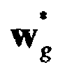
- the expression of SINR g does not depend only upon the weighting coefficients w k * l m relative to user g ( i . e . the SFTF vector w g * relative to user g ) but also upon the weighting coefficients relative to the other users k ⁇ g ( i . e the SFTF vectors w k * relative to the users k ⁇ g ).
- This can be attributed to the fact that the MAI affecting user g is influenced by the distribution in space and frequency of the signals transmitted to the other users k ⁇ g .
- a change of the SFTF vector relative to a given user modifies the SINRs of all the other active users.
- SINR g m P g MAI g m + ⁇ 2
- p MAI g ⁇ k w g H ⁇ v kg ⁇ v kg H ⁇ w g
- the downlink channel coefficients h g ( l,m ) constituting the vector h g are assumed identical to the corresponding uplink channel coefficients, which are in turn estimated from pilot symbols transmitted from the active users to the base station.
- I ML - 1 c ⁇ g * ⁇ h ⁇ g ⁇ c ⁇ g which can be further simplified if the spreading sequences are such that c g l .
- the receiving process carried out at the mobile terminals can be drastically simplified as shown in Fig. 4.
- the MC-CDMA receiver for a user g is schematically represented in Fig. 4 and comprises modules 410g to 450g identical to the corresponding modules 210g to 250g of Fig. 2.
- a simple despreading is effected at the output of the FFT module 420 g and no equalisation is required anymore.
- an estimation of the downlink channel coefficients is not needed at the receiver side, thus relieving the mobile terminal of the computation burden associated therewith.
- the filtering in the frequency domain performed at the transmission side by the weighting coefficients of SFTF vector w g * fully or almost fully pre-compensates for the fading on the carriers of the downlink transmission channel.
- the downlink channel coefficients h g (l,m) are coarsely estimated by the MC-CDMA transmitter and a complementary equalisation is performed at the receiving side.
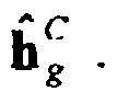
- the MC-CDMA transmitter estimates the coefficients h g (l,m) from the DOAs of the signal received by the antenna array from user g and uses these estimates h ⁇ ⁇ g l m as elements of the vector h ⁇ b C .
- Fig. 5 shows schematically a receiver for use with a MC-CDMA transmitter according to the latter variant.
- a further advantageous aspect of the invention lies in the possibility of increasing the capacity of a MC-CDMA system. It is reminded that the capacity of a conventional MC-CDMA system is limited by the number of available spreading codes (or spreading sequences), which is equal to the number L of subcarriers when the codes are chosen orthogonal.
- the spreading codes are reallocated e.g in the natural order c 1 , c 2 ,.., so that two users k and k + L share the same spreading code c k .
- MC-CDMA transmitter illustrated in Fig. 3 has been described in terms of functional modules e.g. computing or estimating means, it will be appreciated by the man skilled in the art that all or part of this device can be implemented by means of a single processor either dedicated for performing all the functions depicted or in the form of a plurality of processors either dedicated or programmed for each performing one or some of said functions.
Landscapes
- Engineering & Computer Science (AREA)
- Signal Processing (AREA)
- Computer Networks & Wireless Communication (AREA)
- Power Engineering (AREA)
- Quality & Reliability (AREA)
- Mobile Radio Communication Systems (AREA)
- Variable-Direction Aerials And Aerial Arrays (AREA)
- Radio Transmission System (AREA)
Abstract
Description
- The present invention concerns a method of transmission from a base station of a MC-CDMA telecommunication system to a plurality of users thereof.
- MC-CDMA has been receiving widespread interest for wireless broadband multimedia applications. Multi-Carrier Code Division Multiple Access (MC-CDMA) combines OFDM (Orthogonal Frequency Division Multiplex) modulation and the CDMA multiple access technique. This multiple access technique was proposed for the first time by N. Yee et al. in the article entitled "Multicarrier CDMA in indoor wireless radio networks" which appeared in Proceedings of PIMRC'93, Vol. 1, pages 109-113, 1993. The developments of this technique were reviewed by S. Hara et al. in the article entitled "Overview of Multicarrier CDMA" published in IEEE Communication Magazine, pages 126-133, December 1997.
- Unlike DS-CDMA (Direct Spread Code Division Multiple Access), in which the signal of each user is multiplied in the time domain in order to spread its frequency spectrum, the signature here multiplies the signal in the frequency domain, each element of the signature multiplying the signal of a different sub-carrier.
- In general, MC-CDMA combines the advantageous features of CDMA and OFDM, i.e. high spectral efficiency, multiple access capabilities, robustness in presence of frequency selective channels, high flexibility, narrow-band interference rejection, simple one-tap equalisation, etc.
- Fig. 1 illustrates schematically the structure of a MC-CDMA transmitter transmitting a plurality of MC-CDMA symbols to a plurality K of users. For example, we suppose that the transmitter is located in a base station of a MC-CDMA transmission system and transmits MC-CDMA symbols to a plurality of users over a plurality of downlink transmission channels.
- Let dk (n) be a complex symbol to be transmitted from the base station to user k at time nT, where dk (n) belongs to the modulation alphabet and let denote


- The result of the multiplication of the complex value


adder 150 to the similar MC-CDMA symbols Sk , to be transmitted to the other users k'≠k. The resulting sum S is then filtered and RF frequency up-converted (not shown) before being transmitted by the base station. The MC-CDMA method can essentially be regarded as a spreading in the spectral domain (before IFFT) followed by an OFDM modulation. - The signal Sk at time t which is supplied to the
adder 150 before being transmitted over the downlink transmission channel can therefore be written, if we omit the prefix:
where fℓ = ((ℓ -1) - L/2)/T, ℓ = 1,..,L are the frequencies of the OFDM multiplex. More precisely, it should be understood that the transmitted signal is in fact Re(Sk (t)exp(j2πF 0 t)) where Re(.) stands for the real part and F0 is the RF carrier frequency. In other words, Sk (t) is the complex envelope of the transmitted signal. - The resulting sum signal S can be written at time t:

- A MC-CDMA receiver for a given user g has been illustrated schematically in Fig. 2. Since we consider here the downlink, the receiver is located in the mobile terminal.
- After baseband demodulation, the signal is sampled at the "chip" frequency and the samples belonging to the guard interval are eliminated. The signal thus obtained can be written:

where t takes successive sampling time values, K is the number of users and hg (ℓ) represents the response of the downlink channel of the user g to the frequency of the subcarrier ℓ of the MC-CDMA symbol transmitted at time n.T and where b(t) is the received noise. - The samples obtained by sampling the demodulated signal at the "chip" frequency are serial to parallel converted in the serial to parallel converter 210 g before undergoing an FFT in the module 220 g . The samples in the frequency domain, output from 220g, are despread by the spreading sequence of user g and equalised so as to compensate for the dispersive effects of the downlink transmission channel. To do this, the samples of the frequency domain are multiplied (by the
multipliers 

- MRC (Maximum Ratio Combining) equalisation according to which

- EGC (Equal Gain Combining) equalisation according to which qℓ = e - jϕ
ℓ where hℓ = pte -jϕ ℓ - ZF (Zero Forcing) equalisation where

- MMSE (Minimum Mean Square Error) equalisation where

- After multiplication, the samples are added in
adder 240g to output the resulting signal rg :

- The first term of expression (5) corresponds to the desired received signal dedicated to user g, the second term correspond to Multiple Access Interference (MAI) and the third term corresponds to residual noise. The Multiple Access Interference stems from the fact that a downlink channel carries the signals to a plurality of users.
- The resulting signal rg is a decision variable which is detected in detector 250 g for supplying an estimated symbol d̂g . The detection implemented can be a hard or a soft detection (in the
latter case detector 250g can simply be omitted). Without loss of generality, it is assumed in the following that a soft detection is implemented and therefore that d̂g = rg . - The capacity of a MC-CDMA system is basically limited by Multiple Access Interference. A possible way to combat MAI and consequently increase the system capacity is to use a spatial filtering technique to separate the links from or to different users. Spatial filtering is generally obtained by using antenna arrays for forming a plurality of beams in different directions. It has been recently proposed to use antenna arrays in MC-CDMA systems, in particular for transmission as disclosed in the article by M. Fujii entitled "Multibeam-time transmit diversity for OFDM-CDMA" published in Proc. of Globecom 2001, vol. 25, pp. 3095-3099 and in the article by C.K. Kim et al. entitled "Performance analysis of an MC-CDMA system with antenna array in a fading channel", published in IEICE Trans. Commun. Vol. E83-B, N°1, January 2000, pp. 84-92. However, when a user-specific spatial filtering technique is used for downlink transmission, in other words when a transmit beam is formed for each user at the base station, the frequency separation of the different users is not guaranteed anymore. In other words, although, on one hand, spatial filtering contributes to lower MAI by providing spatial separation of the transmission to the different users, it may have, on the other hand, a deleterious effect on the same MAI by destroying the separation of the users in the frequency domain.
- The following documents are representative of the state of the art. The document authored by DONG GEUN JEONG ET AL and published in VTC 2000-SPRING. 2000 IEEE 51ST. VEHICULAR TECHNOLOGY CONFERENCE PROCEEDINGS. TOKYO, JAPAN, MAY 15-18,2000, IEEE VEHICULAR TECHNOLOGY CONFERENCE, NEW YORK, NY: IEEE, US, vol. 3 OF 3. CONF. 51,15 May 2000 (2000-05-15), pages 1773-1777, XP000968309 ISBN: 0-78035719-1 discloses the EFFECTS OF CHANNEL ESTIMATION ERROR IN MC-CDMA/TDD SYSTEMS as mentioned by the title. The document authored by ZHIYONG PU ET AL and published in VEHICULAR TECHNOLOGY CONFERENCE, 1999 IEEE 49TH HOUSTON, TX, USA 16 20 MAY 1999, PISCATAWAY, NJ, USA,IEEE, US, 16 May 1999 (1999-0516), pages 2134-2138, XP010342238 ISBN: 0-7803-5565-2 discloses the transmission and the reception of TDD multicarrier CDMA signals in mobile communications system. The document authored by INCHEOL JEONG ET AL and published in GLOBAL TELECOMMUNICATIONS CONFERENCE GLOBECOM'99, 5 - 9 December 1999, pages 122-126, XP010373284 Rio de Janeiro, Brazil discloses a TDD-CDMA system with pre-phase subcarrier equalizer using asymmetric modulation scheme in duplex channel. Finally, the document authored by Junqiang Li et al. and published in Vehicular Technology Conference, 2001. VTC 2001 Fall. IEEE VTS 54th, Portugal, Sept 15-18, 2001, pp. 1553-1557, discloses a Spatial multiuser access with MIMO smart antennas for OFDM systems.
- It is a first object of the present invention to propose a new filtering technique for MC-CDMA downlink transmission, which minimises the Multiple Access Interference for the different users of the system. Conversely, for a given MAI level, a second object of the present invention is to increase the capacity of a MC-CDMA system.
- Furthermore, as described above in connection with Fig. 2, the receiving process performed at a mobile terminal (MT) of a MC-CDMA system is relatively complex since it involves in particular the determination of the equalising coefficients qg (ℓ) and the step of equalisation itself. A simplification of the receiving process is therefore desirable all the more since the computation and power resources at the MT side are critically limited. A third object of the invention is to reduce the complexity of the receiving process at a mobile terminal without sacrificing the quality of service.
- The above-mentioned objects are attained by the transmitting method of the invention as defined in
claim 1. Advantageous embodiments of the invention are defined in the appended dependent claims. - The advantages and characteristics of the invention will emerge from a reading of the following description given in relation to the accompanying figures, amongst which:
- Fig. 1 depicts schematically the structure of an MC-CDMA transmitter known from the state of the art;
- Fig. 2 depicts schematically the structure of an MC-CDMA receiver known from the state of the art;
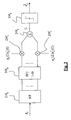
- Fig. 3 depicts schematically the structure of an MC-CDMA transmitter according to the invention;
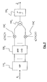
- Fig. 4 depicts schematically the structure of a first MC-CDMA receiver to be used with the MC-CDMA transmitter according to a first embodiment of the invention;
- Fig. 5 depicts schematically the structure of a second MC-CDMA receiver to be used with the MC-CDMA transmitter according to a second embodiment of the invention.
- We refer back again to the context of a MC-CDMA system comprising a base station transmitting a plurality of symbols to a plurality K of active users k=1,..,K sharing the same carriers of an OFDM multiplex.
- The basic idea underlying the invention is to use a filtering technique at the transmission side which is jointly optimised in space and frequency for all the active users. More specifically, if an array of M antennas is used at the base station, the signal transmitted to user k by antenna m can be expressed as:

where


- If we assume that the signals transmitted by the base station to the K users are synchronous, the signal transmitted to all the users by antenna m can be simply expressed as:

- Fig. 3 illustrates schematically a MC-CDMA transmitter using the spatial filtering method according to the invention. The transmitter comprises K identical branches, each branch corresponding to a given active user. The branch dedicated to user k comprises a multiplier 310 k , a
demultiplexer 320 k and aparallel multiplier 330 k connected in series. For example, the branch dedicated touser 1 illustrated in the upper part of the Fig. comprises a multiplier 3101 for multiplying the complex value
demultiplexer 3201 for serial-to-parallel converting the spread complex values, aparallel multiplier 3301 for multiplying each of the spread complex values
weighting vector 
M vectors 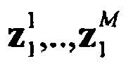


parallel multiplier 330 k of the k th branch is constituted of Mvectors 

- For a given user k the complex weighting coefficients


antenna 1, user k andsubcarriers 1 to L, the second L elements of which corresponding to the weighting coefficients for antenna 2, user k andsubcarriers 1 to L, and so on. As the coefficients


- The MC-CDMA transmitter is further provided with a plurality M of
adders 3401,..,340 M , eachadder 340 m adding thesignal vectors 
parallel multipliers 3301,..,330 M and supplying the resulting vectors to themodules 3501,..,350 M respectively. More precisely, each module 350 m (identical to the module 130 k in Fig. 1) performs an inverse Fast Fourier Transform on the vector of compound frequency components
- As described further below, the SFTF vectors


calculation module 380 from estimates of the coefficients of the downlink transmission channels and supplied to theparallel multipliers 3301,..,330 K . It is assumed in the following that the transmission is free from inter-carrier interference and inter-symbol interference (the latter, thanks to prefix insertion). In such instance, the downlink transmission channel between antenna m of the base station and the mobile terminal of user k can be characterised by a single multiplicative complex coefficient hk (ℓ,m) (hereinafter called channel coefficient) for each subcarrier ℓ. The coefficients hk (ℓ,m) are assumed identical for the downlink and the uplink channels, assumption which is verified in practice when the MC-CDMA system operates in TDD (Time Division Duplex) mode. The estimates of the channel coefficients are hereinafter denoted ĥk(ℓ,m). - The channel coefficients hk (ℓ,m) depend on the spatial signature of the downlink multipath channel and the fading coefficient of the channel. The spatial signature of the channel (supposed identical for downlink and uplink) is defined by the directions of transmission of the signal to user k or, equivalently by the direction of arrival (DOAs) of the signal transmitted by user k to the base station. It should be understood that the coefficients hk (ℓ,m) for a given user k reflect not only the directivity pattern of the (transmit or receive) beam for this user at the various subcarrier frequencies but also the fading of the transmission channel at these frequencies.
- If we now consider a mobile terminal of a given user g having the structure illustrated in Fig. 2 and receiving a signal transmitted by the MC-CDMA of Fig. 3, the decision variable can be expressed as, similar to (4):


where ng (ℓ) are Gaussian noise samples relative to the different carriers and
FFT module 220g. As it will be apparent to the man skilled in the art, the first term of expression (9) corresponds to the desired signal, the second term corresponds to the multiple access interference and the final term corresponds to the residual noise after despreading. - The expression (9) can be equivalently formulated in a more concise form:

where the boldface letters represent vectors and: - c̃ k is a vector of size M.L defined

- ẽ g is a vector of size M.L defined as


- h g is a vector of size M.L defined as h g = (hg (1,1),..,hg (L,1),..,hg (1,M),..,hg (L,M),..,hg (L,M) T the first L elements of which corresponding to the channel between
antenna 1 and user g, the second L elements of which corresponding to the channel between antenna 2 and user g and so on; -

- e g and n g are respectively defined as e g = (eg (1),..,eg(L))T and n g = (ng (1),..,ng (L)) T ;
- (.) H denotes the hermitian transpose operator, u.v denotes the scalar product of vectors u and v, u o v denotes the element wise product of vectors u and v, i.e. the i th element of vector u o v is the product of the i th element of vector u and the i th element of vector v.
- According to a first advantageous aspect of the invention, for a given user g, a set of weighting coefficients


- According to a second advantageous aspect of the invention, there is performed a joint MAI minimisation criterion taking into account all the active users. More precisely, the proposed minimisation criterion is not aimed at merely minimising the MAI affecting the reception of a given active user irrespective of the MAI affecting the reception of the other active users but takes also into account the MAIs affecting the latter users induced by the signal transmitted to the user in question.
- According to a third advantageous aspect of the invention, there is used a MAI minimisation criterion taking into account the transmit power constraint of the MC-CDMA transmitter, which is itself inherently limited by the total transmit power of the base station.
- In order to explain in further detail the transmission method according to the invention, we consider first a criterion based on the maximisation of the signal to interference plus noise ratio (SINR) relative to a given active user g, under the constraint of a fixed transmit power level for this user.
- The signal to interference plus noise ratio relative to the user g can be expressed as:

where Pg is the power of the desired signal received by user g, MAIg is the MAI level affecting the desired signal and σ2 is variance of the residual noise after despreading. - From the first term of (10) and assuming that the average power of the symbols dg is unity, the power of the desired signal received by user g can be expressed as:

- From the second term of (10) and assuming that the average power of the symbols dk is unity, the multiple access interference level MAIg can be expressed as:

where pMAI (k → g) reflects the normalised contribution of (the signal transmitted to) user k to the MAI affecting user g and is defined as:
where
- From (12), (13) and (14), the signal to interference plus noise ratio relative to user g can be rewritten:

- As it is apparent from (15), the expression of SINRg does not depend only upon the weighting coefficients



- According to the invention, the problem of maximising the SINRg is elegantly solved by observing that in practice the channel response vectors h k , k=1,..,K have the same statistical properties and that consequently for two given users k and k' the normalised interference contributions PMAI (k → k') and PMAI (k'→ k) can be considered equal, which is especially justified when the same method of space-time filtering is applied to all the users.
- More precisely, there is proposed a criterion based upon a pseudo signal to noise plus interference ratio denoted


where


where Φ g is the quadratic matrix
- The pseudo signal to noise plus interference ratio can therefore be reformulated as:

- For a fixed predetermined transmit power value Ptg , the constraint on the transmit power for user g can be expressed as a constraint on the module of the SFTF vector w g , namely

- From (17), the maximisation of


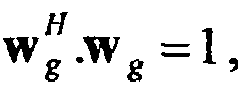
- It should be noted that expression (18) depends only on the SFTF vector w g and is invariant by multiplication of w g with a constant. Defining= βw g where β is a scalar, it is there possible to look for the optimal vector
 that verifies(
 o h g o c̃ g ) = 1, and then to normalise the result by the factor
 in order to obtain w g . The optimum pre-distortion vector SFTF
 must therefore satisfy:
- For solving this problem, we introduce the Lagrange function:

- By calculating the gradient according to the vectors(the same result can be obtained by calculating the gradient according to the vector
 ):
):

- Finally, we can conclude that the optimal SFTF vectoris given by :


- In practice, the downlink channel coefficients hg (ℓ,m) constituting the vector h g are assumed identical to the corresponding uplink channel coefficients, which are in turn estimated from pilot symbols transmitted from the active users to the base station.
- Turning back to Fig. 3 and denoting ĥ k the vector of the estimates ĥk (ℓ,m), the
calculation module 380 determines for each active user k the SFTF vector

where the coefficient µ k is given by the constraint upon the transmit power for user k (i.e.

- According to first embodiment of the invention, the SFTF vector

calculation module 380 from:


- In such instance, the receiving process carried out at the mobile terminals can be drastically simplified as shown in Fig. 4. The MC-CDMA receiver for a user g is schematically represented in Fig. 4 and comprises
modules 410g to 450g identical to the correspondingmodules 210g to 250g of Fig. 2. However, in contrast with the MC-CDMA receiver of the prior art (Fig. 2), a simple despreading is effected at the output of the FFT module 420 g and no equalisation is required anymore. In particular, an estimation of the downlink channel coefficients is not needed at the receiver side, thus relieving the mobile terminal of the computation burden associated therewith. - It should be appreciated that the filtering in the frequency domain performed at the transmission side by the weighting coefficients of SFTF vector

- According to a second embodiment of the invention, the downlink channel coefficients hg (ℓ,m) are coarsely estimated by the MC-CDMA transmitter and a complementary equalisation is performed at the receiving side.
- This is for example the case if the estimates of the uplink channel coefficients (from which the latter are derived) are updated at a rate lower than the actual variation thereof. More specifically, denoting


- In a further variant, the vector of coarse estimates,


calculation module 380, is derived from the spatial signature of user g. More specifically, it is assumed that the channel coefficients hg (ℓ, m) can be decomposed into :
whereh g (ℓ, m) accounts for the spatial signature of user g (varying relatively slowly in time) and ηg (ℓ) accounts for the frequency fading of the channel. The MC-CDMA transmitter estimates the coefficientsh g(ℓ,m) from the DOAs of the signal received by the antenna array from user g and uses these estimates
- Fig. 5 shows schematically a receiver for use with a MC-CDMA transmitter according to the latter variant. The
modules 510 g to 550 g are identical to the corresponding modules 210 g to 250 g of Fig. 2 and the compensation for the fast fading factors ηg (ℓ) is ensured here by equalising coefficients
- A further advantageous aspect of the invention lies in the possibility of increasing the capacity of a MC-CDMA system. It is reminded that the capacity of a conventional MC-CDMA system is limited by the number of available spreading codes (or spreading sequences), which is equal to the number L of subcarriers when the codes are chosen orthogonal. The user separation in the space domain provided by the transmission method according to the invention allows to reuse the same spreading codes for different users. More specifically, a spreading code ck(ℓ), ℓ=1,..,L already allocated to a user k can be also reallocated to a user k' provided users k and k' have substantially different spatial signatures.
- According to a first possible allocation scheme, if the number of active users happens to exceed the number L of available spreading codes (for example, if the available spreading codes are already allocated and if an incoming call is requested), the spreading codes are reallocated e.g in the natural order c 1,c 2,.., so that two users k and k+L share the same spreading code c k . In order to reduce the interference occurring when users k and k+L exhibit similar spatial signatures, it is further proposed to apply random scrambling codes on top of the available spreading codes. More specifically, if a symbol has to be transmitted to a user k belonging to a given set Ω p , where p ∈ {1,..,P}, it is multiplied by the following sequence:

where user index k may be greater than L, p denotes the integer part of the division k/L and k[L] denotes the rest thereof,
- Since users belonging to a given set Ω p are subjected to the same scrambling code, their respective spreading sequences (as defined in (30)) are orthogonal and, consequently, these users are spatially and frequency separated by the transmission method according to the invention. In contrast, orthogonality is not maintained between spreading sequences allocated to users belonging to different sets. However, the latter users still benefit from the spatial separation provided by said transmission method as well as from the interference reduction due to the random scrambling.
- Although the MC-CDMA transmitter illustrated in Fig. 3 has been described in terms of functional modules e.g. computing or estimating means, it will be appreciated by the man skilled in the art that all or part of this device can be implemented by means of a single processor either dedicated for performing all the functions depicted or in the form of a plurality of processors either dedicated or programmed for each performing one or some of said functions.
Claims (4)
- Transmission method for transmitting a plurality of symbols from a base station of a MC-CDMA telecommunication system to a plurality K of users, each symbol dk to be transmitted to a user being spread with a coding sequence ck (ℓ),


where,
c̃ g is a vector of size M.L defined as the concatenation of M times the vector c g =(cg (1),..,cg (L)) T representing the coding sequence of said given user g ;
q̃ g is a vector of size M.L defined as the concatenation of M times the vector q g = (qg (1),..,qg (L)) T representing the equalising coefficients for said given user g;
ĥ g is a vector of size M.L the first L elements of which represent the said estimates of the channel between antenna element 1 and user g, the second L elements of which corresponding to the channel between antenna element 2 and user g and so on;
µg is a scalar coefficient given by the constraint upon the transmit power for user g
I ML is the identity matrix of size M.LxM.L;
σ 2 is the value of said noise variance;
Φ̂ g is a hermitian matrix characterising the multiple access interference generated by user g on the other users ;
and where .o. denotes the element by element multiplication of two vectors. - Transmission method according to claim 1 characterised in that the hermitian matrix is obtained from an expression of the type:

where K is number of users, Ptk is the transmit power for user k and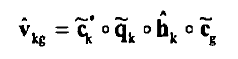
where c̃ k is a vector of size M.L defined as the concatenation of M times the vector ck = (ck(1),..,ck(L))T representing the coding sequence of user k ;
q̃ k is a vector of size M.L defined as the concatenation of M times the vector q k =(qk(1),..,qk(L)) T representing the equalising coefficients for user k.
ĥ k is a vector of size M.L the first L elements of which represent the said estimates of the channel between antenna element 1 and user k, the second L elements of which corresponding to the channel between antenna element 2 and user k and so on. - Transmission method according to claims 1 or 2, characterised in that, if no equalisation is to be performed for a given user g, the vector q̃ k is considered as being equal to the identity matrix of size M.L.
- Transmission method according to claim 3, characterised in that, if no spreading is to be performed for a given user g, the vector c̃ k is considered as being equal to the identity matrix of size M.L.
Priority Applications (6)
| Application Number | Priority Date | Filing Date | Title |
|---|---|---|---|
| DE60223367T DE60223367T2 (en) | 2002-09-05 | 2002-09-05 | A method for transmitting from a base station of an MC-CDMA telecommunication system to a plurality of users |
| EP02292189A EP1396956B1 (en) | 2002-09-05 | 2002-09-05 | MC-CDMA downlink beamforming method with the weights applied to every element of the antenna array being different for every user and every frequency bin, the weights being adapted to maximise the signal to interference and noise ratio |
| AT02292189T ATE377878T1 (en) | 2002-09-05 | 2002-09-05 | MC-CDMA DOWNWARD BEAM FORMATION METHOD WHERE THE ANTENNA ELEMENT WEIGHTS ARE USER AND FREQUENCY INDIVIDUAL AND ADJUSTED TO MAXIMIZE THE SIGNAL INTERFERENCE AND NOISE RATIO |
| US10/623,523 US7336636B2 (en) | 2002-09-05 | 2003-07-22 | MC-CDMA downlink transmission method |
| CNB031554563A CN100539461C (en) | 2002-09-05 | 2003-09-04 | Mc-cdma downlink transmission method |
| JP2003314426A JP4299081B2 (en) | 2002-09-05 | 2003-09-05 | Sending method |
Applications Claiming Priority (1)
| Application Number | Priority Date | Filing Date | Title |
|---|---|---|---|
| EP02292189A EP1396956B1 (en) | 2002-09-05 | 2002-09-05 | MC-CDMA downlink beamforming method with the weights applied to every element of the antenna array being different for every user and every frequency bin, the weights being adapted to maximise the signal to interference and noise ratio |
Publications (2)
| Publication Number | Publication Date |
|---|---|
| EP1396956A1 EP1396956A1 (en) | 2004-03-10 |
| EP1396956B1 true EP1396956B1 (en) | 2007-11-07 |
Family
ID=31502836
Family Applications (1)
| Application Number | Title | Priority Date | Filing Date |
|---|---|---|---|
| EP02292189A Expired - Lifetime EP1396956B1 (en) | 2002-09-05 | 2002-09-05 | MC-CDMA downlink beamforming method with the weights applied to every element of the antenna array being different for every user and every frequency bin, the weights being adapted to maximise the signal to interference and noise ratio |
Country Status (6)
| Country | Link |
|---|---|
| US (1) | US7336636B2 (en) |
| EP (1) | EP1396956B1 (en) |
| JP (1) | JP4299081B2 (en) |
| CN (1) | CN100539461C (en) |
| AT (1) | ATE377878T1 (en) |
| DE (1) | DE60223367T2 (en) |
Cited By (5)
| Publication number | Priority date | Publication date | Assignee | Title |
|---|---|---|---|---|
| US7978649B2 (en) | 2004-07-15 | 2011-07-12 | Qualcomm, Incorporated | Unified MIMO transmission and reception |
| US7991065B2 (en) | 2004-06-30 | 2011-08-02 | Qualcomm, Incorporated | Efficient computation of spatial filter matrices for steering transmit diversity in a MIMO communication system |
| US8169889B2 (en) | 2004-02-18 | 2012-05-01 | Qualcomm Incorporated | Transmit diversity and spatial spreading for an OFDM-based multi-antenna communication system |
| US8285226B2 (en) | 2004-05-07 | 2012-10-09 | Qualcomm Incorporated | Steering diversity for an OFDM-based multi-antenna communication system |
| US8909174B2 (en) | 2004-05-07 | 2014-12-09 | Qualcomm Incorporated | Continuous beamforming for a MIMO-OFDM system |
Families Citing this family (32)
| Publication number | Priority date | Publication date | Assignee | Title |
|---|---|---|---|---|
| EP1511206B1 (en) * | 2003-09-01 | 2012-12-19 | Mitsubishi Electric R&D Centre Europe B.V. | Method of assigning one or more spreading sequences to users of a multi carrier transmission network |
| US8204149B2 (en) | 2003-12-17 | 2012-06-19 | Qualcomm Incorporated | Spatial spreading in a multi-antenna communication system |
| US7336746B2 (en) | 2004-12-09 | 2008-02-26 | Qualcomm Incorporated | Data transmission with spatial spreading in a MIMO communication system |
| US7447268B2 (en) | 2004-03-31 | 2008-11-04 | Intel Corporation | OFDM system with per subcarrier phase rotation |
| JP4707071B2 (en) * | 2004-08-03 | 2011-06-22 | エージェンシー フォー サイエンス, テクノロジー アンド リサーチ | Signal detection method, detector and computer program product |
| US7978778B2 (en) | 2004-09-03 | 2011-07-12 | Qualcomm, Incorporated | Receiver structures for spatial spreading with space-time or space-frequency transmit diversity |
| FR2875658B1 (en) * | 2004-09-21 | 2007-03-02 | Commissariat Energie Atomique | ESTIMATING THE MOST NOISE INTERFERENCE SIGNAL RATIO AT THE OUTPUT OF AN OFDM-CDMA RECEIVER. |
| WO2006052185A1 (en) * | 2004-11-10 | 2006-05-18 | Telefonaktiebolaget Lm Ericsson (Publ) | A method and apparatus for reducing peak power in code multiplexed downlink control channels |
| US8670493B2 (en) | 2005-06-22 | 2014-03-11 | Eices Research, Inc. | Systems and/or methods of increased privacy wireless communications |
| KR100718999B1 (en) * | 2005-07-13 | 2007-05-16 | 엘지전자 주식회사 | Plasma display panel |
| KR100719000B1 (en) * | 2005-07-13 | 2007-05-16 | 엘지전자 주식회사 | Plasma display panel |
| US8064424B2 (en) | 2005-07-22 | 2011-11-22 | Qualcomm Incorporated | SDMA for WCDMA |
| US8855704B2 (en) | 2005-08-26 | 2014-10-07 | Qualcomm Incorporated | Fast cell selection in TD-CDMA (UMTS TDD) |
| US8619884B2 (en) | 2005-09-02 | 2013-12-31 | Qualcomm Incorporated | Communication channel estimation |
| CN100358261C (en) * | 2005-09-13 | 2007-12-26 | 北京交通大学 | An array antenna MC-CDMA system uplink receiving method |
| US8068464B2 (en) | 2005-10-27 | 2011-11-29 | Qualcomm Incorporated | Varying scrambling/OVSF codes within a TD-CDMA slot to overcome jamming effect by a dominant interferer |
| US8130727B2 (en) | 2005-10-27 | 2012-03-06 | Qualcomm Incorporated | Quasi-orthogonal allocation of codes in TD-CDMA systems |
| CN100388648C (en) * | 2006-01-17 | 2008-05-14 | 凯明信息科技股份有限公司 | Device for reducing reception interference in code division multiple access system |
| CN100391130C (en) * | 2006-01-17 | 2008-05-28 | 凯明信息科技股份有限公司 | Method of Reducing Interference in Code Division Multiple Access System |
| CN100391129C (en) * | 2006-01-17 | 2008-05-28 | 凯明信息科技股份有限公司 | Method of Reducing Interference in Code Division Multiple Access System |
| CN100388649C (en) * | 2006-01-17 | 2008-05-14 | 凯明信息科技股份有限公司 | Apparatus for Weighting Signal Sequence Using Weight Sequence |
| KR101218495B1 (en) * | 2006-02-21 | 2013-01-18 | 삼성전자주식회사 | An adaptive channel prediction apparatus and method for uplink pre-equalization in mobile communication system using orthgonal frequncy division multiplexing/time division duplex according to the quantity of downlink channel variation |
| US8543070B2 (en) | 2006-04-24 | 2013-09-24 | Qualcomm Incorporated | Reduced complexity beam-steered MIMO OFDM system |
| US8290089B2 (en) | 2006-05-22 | 2012-10-16 | Qualcomm Incorporated | Derivation and feedback of transmit steering matrix |
| US20080031369A1 (en) * | 2006-06-07 | 2008-02-07 | Li Ye Geoffrey | Apparatus and methods for multi-carrier wireless access with energy spreading |
| US8787841B2 (en) | 2006-06-27 | 2014-07-22 | Qualcomm Incorporated | Method and system for providing beamforming feedback in wireless communication systems |
| US7983352B2 (en) * | 2006-09-15 | 2011-07-19 | Futurewei Technologies, Inc. | Power allocation in a MIMO system without channel state information feedback |
| US8112038B2 (en) * | 2006-09-15 | 2012-02-07 | Futurewei Technologies, Inc. | Beamforming with imperfect channel state information |
| WO2008129636A1 (en) * | 2007-04-12 | 2008-10-30 | Fujitsu Limited | Wireless communication quality estimating method and apparatus |
| JP5277673B2 (en) * | 2008-03-17 | 2013-08-28 | 富士通株式会社 | Wireless communication system, wireless communication method, transmission device, and reception device |
| US20110182582A1 (en) * | 2009-04-15 | 2011-07-28 | Nec Laboratories America Inc. | Joint sample rate conversion and cd compensation in frequency domain for coherent polmux |
| CN111211807A (en) * | 2020-03-17 | 2020-05-29 | 南京凯瑞得信息科技有限公司 | Multi-channel carrier superposition multi-address access method and system |
Family Cites Families (1)
| Publication number | Priority date | Publication date | Assignee | Title |
|---|---|---|---|---|
| SG108240A1 (en) * | 2000-02-23 | 2005-01-28 | Ntt Docomo Inc | Multi-carrier cdma radio transmitting method and apparatus, and channel estimation method and apparatus for multi-carrier cdma radio transmitting system |
-
2002
- 2002-09-05 AT AT02292189T patent/ATE377878T1/en not_active IP Right Cessation
- 2002-09-05 EP EP02292189A patent/EP1396956B1/en not_active Expired - Lifetime
- 2002-09-05 DE DE60223367T patent/DE60223367T2/en not_active Expired - Lifetime
-
2003
- 2003-07-22 US US10/623,523 patent/US7336636B2/en not_active Expired - Fee Related
- 2003-09-04 CN CNB031554563A patent/CN100539461C/en not_active Expired - Fee Related
- 2003-09-05 JP JP2003314426A patent/JP4299081B2/en not_active Expired - Fee Related
Cited By (7)
| Publication number | Priority date | Publication date | Assignee | Title |
|---|---|---|---|---|
| US8169889B2 (en) | 2004-02-18 | 2012-05-01 | Qualcomm Incorporated | Transmit diversity and spatial spreading for an OFDM-based multi-antenna communication system |
| US8285226B2 (en) | 2004-05-07 | 2012-10-09 | Qualcomm Incorporated | Steering diversity for an OFDM-based multi-antenna communication system |
| US8909174B2 (en) | 2004-05-07 | 2014-12-09 | Qualcomm Incorporated | Continuous beamforming for a MIMO-OFDM system |
| US8923785B2 (en) | 2004-05-07 | 2014-12-30 | Qualcomm Incorporated | Continuous beamforming for a MIMO-OFDM system |
| US7991065B2 (en) | 2004-06-30 | 2011-08-02 | Qualcomm, Incorporated | Efficient computation of spatial filter matrices for steering transmit diversity in a MIMO communication system |
| US7978649B2 (en) | 2004-07-15 | 2011-07-12 | Qualcomm, Incorporated | Unified MIMO transmission and reception |
| US8767701B2 (en) | 2004-07-15 | 2014-07-01 | Qualcomm Incorporated | Unified MIMO transmission and reception |
Also Published As
| Publication number | Publication date |
|---|---|
| JP4299081B2 (en) | 2009-07-22 |
| US7336636B2 (en) | 2008-02-26 |
| US20050030925A1 (en) | 2005-02-10 |
| ATE377878T1 (en) | 2007-11-15 |
| CN100539461C (en) | 2009-09-09 |
| CN1489404A (en) | 2004-04-14 |
| DE60223367D1 (en) | 2007-12-20 |
| JP2004104790A (en) | 2004-04-02 |
| DE60223367T2 (en) | 2008-02-14 |
| EP1396956A1 (en) | 2004-03-10 |
Similar Documents
| Publication | Publication Date | Title |
|---|---|---|
| US7336636B2 (en) | MC-CDMA downlink transmission method | |
| EP1742405B1 (en) | Method for channel estimation with spatial division multiplexing in an orthogonal frequency division multiplexing system with multiple antennas | |
| KR100382396B1 (en) | System for radio transmission of digital signals between a plurality of subscriber stations and a base station | |
| US7656936B2 (en) | Method and system for interference reduction in a wireless communication network using a joint detector | |
| US9374143B2 (en) | Estimating frequency-offsets and multi-antenna channels in MIMO OFDM systems | |
| KR100948007B1 (en) | Wireless transmission using an adaptive transmit antenna array | |
| US8219078B2 (en) | Method and apparatus for multi-user multi-input multi-output transmission | |
| EP1328071B1 (en) | MC-CDMA uplink per carrier pre-distortion method | |
| US7746766B2 (en) | Systems and methods for obtaining an optimum transmission format of reference signals to maximize capacity and minimize peak to average power ratio | |
| US20100183089A1 (en) | Method for signal transmission-reception in a multi-user multiple transmit and multiple receive antenna radio communication system | |
| EP1328083B1 (en) | Pre-distortion method for an MC-CDMA uplink | |
| US7894516B2 (en) | Method for equalizing a digital signal and equalizer | |
| EP2011293B1 (en) | Frequency domain channel estimation in a single carrier frequency division multiple access system | |
| US20050265429A1 (en) | Transmitter and receiver for fast frequency for fast frequency hopping in an orthogonal frequency division multiplexing system | |
| US9948373B2 (en) | MIMO-FBMC transmitter/receiver with linear precoding implemented in the frequency domain | |
| US7203157B2 (en) | Equalization method and device of the GMMSE type | |
| US7058115B2 (en) | Equalization method and device of the GMMSE type | |
| EP1629649B1 (en) | Apparatus and method for precoding a multicarrier signal | |
| US7333538B2 (en) | Equalisation method and device of the GMMSE type | |
| Henkel et al. | Peak-to-average ratio reduction with tone reservation in multi-user and MIMO OFDM | |
| Salzer et al. | Comparison of antenna array techniques for the downlink of multi-carrier CDMA systems | |
| Kurayama et al. | Transmit equalization for asynchronous NOMA downlink | |
| Siddiqui et al. | On interference in uplink SDMA SC-FDE system | |
| JP2005333443A (en) | Method of performing transmission diversity, radio apparatus, and communication system using the same | |
| Panayirci et al. | Joint data detection and channel estimation for uplink MC-CDMA systems over frequency selective channels |
Legal Events
| Date | Code | Title | Description |
|---|---|---|---|
| PUAI | Public reference made under article 153(3) epc to a published international application that has entered the european phase |
Free format text: ORIGINAL CODE: 0009012 |
|
| AK | Designated contracting states |
Kind code of ref document: A1 Designated state(s): AT BE BG CH CY CZ DE DK EE ES FI FR GB GR IE IT LI LU MC NL PT SE SK TR |
|
| AX | Request for extension of the european patent |
Extension state: AL LT LV MK RO SI |
|
| 17P | Request for examination filed |
Effective date: 20040410 |
|
| 17Q | First examination report despatched |
Effective date: 20040513 |
|
| AKX | Designation fees paid |
Designated state(s): AT BE BG CH CY CZ DE DK EE ES FI FR GB GR IE IT LI LU MC NL PT SE SK TR |
|
| GRAP | Despatch of communication of intention to grant a patent |
Free format text: ORIGINAL CODE: EPIDOSNIGR1 |
|
| GRAS | Grant fee paid |
Free format text: ORIGINAL CODE: EPIDOSNIGR3 |
|
| GRAA | (expected) grant |
Free format text: ORIGINAL CODE: 0009210 |
|
| AK | Designated contracting states |
Kind code of ref document: B1 Designated state(s): AT BE BG CH CY CZ DE DK EE ES FI FR GB GR IE IT LI LU MC NL PT SE SK TR |
|
| REG | Reference to a national code |
Ref country code: GB Ref legal event code: FG4D |
|
| REG | Reference to a national code |
Ref country code: IE Ref legal event code: FG4D |
|
| REG | Reference to a national code |
Ref country code: CH Ref legal event code: EP |
|
| REF | Corresponds to: |
Ref document number: 60223367 Country of ref document: DE Date of ref document: 20071220 Kind code of ref document: P |
|
| ET | Fr: translation filed | ||
| PG25 | Lapsed in a contracting state [announced via postgrant information from national office to epo] |
Ref country code: CH Free format text: LAPSE BECAUSE OF FAILURE TO SUBMIT A TRANSLATION OF THE DESCRIPTION OR TO PAY THE FEE WITHIN THE PRESCRIBED TIME-LIMIT Effective date: 20071107 Ref country code: LI Free format text: LAPSE BECAUSE OF FAILURE TO SUBMIT A TRANSLATION OF THE DESCRIPTION OR TO PAY THE FEE WITHIN THE PRESCRIBED TIME-LIMIT Effective date: 20071107 Ref country code: NL Free format text: LAPSE BECAUSE OF FAILURE TO SUBMIT A TRANSLATION OF THE DESCRIPTION OR TO PAY THE FEE WITHIN THE PRESCRIBED TIME-LIMIT Effective date: 20071107 Ref country code: SE Free format text: LAPSE BECAUSE OF FAILURE TO SUBMIT A TRANSLATION OF THE DESCRIPTION OR TO PAY THE FEE WITHIN THE PRESCRIBED TIME-LIMIT Effective date: 20080207 Ref country code: ES Free format text: LAPSE BECAUSE OF FAILURE TO SUBMIT A TRANSLATION OF THE DESCRIPTION OR TO PAY THE FEE WITHIN THE PRESCRIBED TIME-LIMIT Effective date: 20080218 |
|
| NLV1 | Nl: lapsed or annulled due to failure to fulfill the requirements of art. 29p and 29m of the patents act | ||
| PG25 | Lapsed in a contracting state [announced via postgrant information from national office to epo] |
Ref country code: BG Free format text: LAPSE BECAUSE OF FAILURE TO SUBMIT A TRANSLATION OF THE DESCRIPTION OR TO PAY THE FEE WITHIN THE PRESCRIBED TIME-LIMIT Effective date: 20080207 |
|
| REG | Reference to a national code |
Ref country code: CH Ref legal event code: PL |
|
| PG25 | Lapsed in a contracting state [announced via postgrant information from national office to epo] |
Ref country code: AT Free format text: LAPSE BECAUSE OF FAILURE TO SUBMIT A TRANSLATION OF THE DESCRIPTION OR TO PAY THE FEE WITHIN THE PRESCRIBED TIME-LIMIT Effective date: 20071107 |
|
| PG25 | Lapsed in a contracting state [announced via postgrant information from national office to epo] |
Ref country code: CZ Free format text: LAPSE BECAUSE OF FAILURE TO SUBMIT A TRANSLATION OF THE DESCRIPTION OR TO PAY THE FEE WITHIN THE PRESCRIBED TIME-LIMIT Effective date: 20071107 Ref country code: DK Free format text: LAPSE BECAUSE OF FAILURE TO SUBMIT A TRANSLATION OF THE DESCRIPTION OR TO PAY THE FEE WITHIN THE PRESCRIBED TIME-LIMIT Effective date: 20071107 |
|
| PG25 | Lapsed in a contracting state [announced via postgrant information from national office to epo] |
Ref country code: BE Free format text: LAPSE BECAUSE OF FAILURE TO SUBMIT A TRANSLATION OF THE DESCRIPTION OR TO PAY THE FEE WITHIN THE PRESCRIBED TIME-LIMIT Effective date: 20071107 Ref country code: SK Free format text: LAPSE BECAUSE OF FAILURE TO SUBMIT A TRANSLATION OF THE DESCRIPTION OR TO PAY THE FEE WITHIN THE PRESCRIBED TIME-LIMIT Effective date: 20071107 |
|
| PLBE | No opposition filed within time limit |
Free format text: ORIGINAL CODE: 0009261 |
|
| STAA | Information on the status of an ep patent application or granted ep patent |
Free format text: STATUS: NO OPPOSITION FILED WITHIN TIME LIMIT |
|
| PG25 | Lapsed in a contracting state [announced via postgrant information from national office to epo] |
Ref country code: PT Free format text: LAPSE BECAUSE OF FAILURE TO SUBMIT A TRANSLATION OF THE DESCRIPTION OR TO PAY THE FEE WITHIN THE PRESCRIBED TIME-LIMIT Effective date: 20080407 |
|
| 26N | No opposition filed |
Effective date: 20080808 |
|
| PG25 | Lapsed in a contracting state [announced via postgrant information from national office to epo] |
Ref country code: GR Free format text: LAPSE BECAUSE OF FAILURE TO SUBMIT A TRANSLATION OF THE DESCRIPTION OR TO PAY THE FEE WITHIN THE PRESCRIBED TIME-LIMIT Effective date: 20080208 |
|
| PG25 | Lapsed in a contracting state [announced via postgrant information from national office to epo] |
Ref country code: FI Free format text: LAPSE BECAUSE OF FAILURE TO SUBMIT A TRANSLATION OF THE DESCRIPTION OR TO PAY THE FEE WITHIN THE PRESCRIBED TIME-LIMIT Effective date: 20071107 |
|
| PG25 | Lapsed in a contracting state [announced via postgrant information from national office to epo] |
Ref country code: EE Free format text: LAPSE BECAUSE OF FAILURE TO SUBMIT A TRANSLATION OF THE DESCRIPTION OR TO PAY THE FEE WITHIN THE PRESCRIBED TIME-LIMIT Effective date: 20071107 Ref country code: MC Free format text: LAPSE BECAUSE OF NON-PAYMENT OF DUE FEES Effective date: 20080930 |
|
| PG25 | Lapsed in a contracting state [announced via postgrant information from national office to epo] |
Ref country code: CY Free format text: LAPSE BECAUSE OF FAILURE TO SUBMIT A TRANSLATION OF THE DESCRIPTION OR TO PAY THE FEE WITHIN THE PRESCRIBED TIME-LIMIT Effective date: 20071107 Ref country code: IE Free format text: LAPSE BECAUSE OF NON-PAYMENT OF DUE FEES Effective date: 20080905 |
|
| PG25 | Lapsed in a contracting state [announced via postgrant information from national office to epo] |
Ref country code: LU Free format text: LAPSE BECAUSE OF NON-PAYMENT OF DUE FEES Effective date: 20080905 |
|
| PG25 | Lapsed in a contracting state [announced via postgrant information from national office to epo] |
Ref country code: TR Free format text: LAPSE BECAUSE OF FAILURE TO SUBMIT A TRANSLATION OF THE DESCRIPTION OR TO PAY THE FEE WITHIN THE PRESCRIBED TIME-LIMIT Effective date: 20071107 |
|
| PG25 | Lapsed in a contracting state [announced via postgrant information from national office to epo] |
Ref country code: IT Free format text: LAPSE BECAUSE OF NON-PAYMENT OF DUE FEES Effective date: 20080930 |
|
| PGFP | Annual fee paid to national office [announced via postgrant information from national office to epo] |
Ref country code: DE Payment date: 20130919 Year of fee payment: 12 |
|
| PGFP | Annual fee paid to national office [announced via postgrant information from national office to epo] |
Ref country code: GB Payment date: 20130919 Year of fee payment: 12 |
|
| PGFP | Annual fee paid to national office [announced via postgrant information from national office to epo] |
Ref country code: FR Payment date: 20130926 Year of fee payment: 12 |
|
| REG | Reference to a national code |
Ref country code: DE Ref legal event code: R119 Ref document number: 60223367 Country of ref document: DE |
|
| GBPC | Gb: european patent ceased through non-payment of renewal fee |
Effective date: 20140905 |
|
| REG | Reference to a national code |
Ref country code: DE Ref legal event code: R119 Ref document number: 60223367 Country of ref document: DE Effective date: 20150401 |
|
| REG | Reference to a national code |
Ref country code: FR Ref legal event code: ST Effective date: 20150529 |
|
| PG25 | Lapsed in a contracting state [announced via postgrant information from national office to epo] |
Ref country code: GB Free format text: LAPSE BECAUSE OF NON-PAYMENT OF DUE FEES Effective date: 20140905 Ref country code: DE Free format text: LAPSE BECAUSE OF NON-PAYMENT OF DUE FEES Effective date: 20150401 |
|
| PG25 | Lapsed in a contracting state [announced via postgrant information from national office to epo] |
Ref country code: FR Free format text: LAPSE BECAUSE OF NON-PAYMENT OF DUE FEES Effective date: 20140930 |