EP1396952B1 - Method and apparatus for providing dispersion compensation - Google Patents
Method and apparatus for providing dispersion compensation Download PDFInfo
- Publication number
- EP1396952B1 EP1396952B1 EP03010412A EP03010412A EP1396952B1 EP 1396952 B1 EP1396952 B1 EP 1396952B1 EP 03010412 A EP03010412 A EP 03010412A EP 03010412 A EP03010412 A EP 03010412A EP 1396952 B1 EP1396952 B1 EP 1396952B1
- Authority
- EP
- European Patent Office
- Prior art keywords
- dispersion
- fiber
- rds
- transmission
- dcf
- Prior art date
- Legal status (The legal status is an assumption and is not a legal conclusion. Google has not performed a legal analysis and makes no representation as to the accuracy of the status listed.)
- Expired - Lifetime
Links
- 239000006185 dispersion Substances 0.000 title claims description 133
- 238000000034 method Methods 0.000 title claims description 7
- 239000000835 fiber Substances 0.000 claims description 124
- 230000005540 biological transmission Effects 0.000 claims description 114
- 239000013307 optical fiber Substances 0.000 claims description 9
- 230000003287 optical effect Effects 0.000 claims description 8
- 230000008878 coupling Effects 0.000 claims description 7
- 238000010168 coupling process Methods 0.000 claims description 7
- 238000005859 coupling reaction Methods 0.000 claims description 7
- 101150058910 RDS1 gene Proteins 0.000 claims 5
- 101100219167 Saccharomyces cerevisiae (strain ATCC 204508 / S288c) BUL1 gene Proteins 0.000 claims 5
- 101100140267 Saccharomyces cerevisiae (strain ATCC 204508 / S288c) RDS2 gene Proteins 0.000 claims 2
- 239000003365 glass fiber Substances 0.000 description 3
- 238000012986 modification Methods 0.000 description 2
- 230000004048 modification Effects 0.000 description 2
- 238000004519 manufacturing process Methods 0.000 description 1
- 230000003595 spectral effect Effects 0.000 description 1
Images

Classifications
-
- H—ELECTRICITY
- H04—ELECTRIC COMMUNICATION TECHNIQUE
- H04B—TRANSMISSION
- H04B10/00—Transmission systems employing electromagnetic waves other than radio-waves, e.g. infrared, visible or ultraviolet light, or employing corpuscular radiation, e.g. quantum communication
- H04B10/25—Arrangements specific to fibre transmission
- H04B10/2507—Arrangements specific to fibre transmission for the reduction or elimination of distortion or dispersion
- H04B10/2513—Arrangements specific to fibre transmission for the reduction or elimination of distortion or dispersion due to chromatic dispersion
- H04B10/2525—Arrangements specific to fibre transmission for the reduction or elimination of distortion or dispersion due to chromatic dispersion using dispersion-compensating fibres
Definitions
- the present invention relates to optical fibers and, more particularly, to providing dispersion compensation in an optical fiber transmission system over a broad range of wavelengths.
- Dispersion in a glass fiber causes pulse spreading for pulses that include a range of wavelengths, due to the fact that the speed of light in a glass fiber is a function of the transmission wavelength of the light. Pulse broadening is a function of the fiber dispersion, the fiber length and the spectral width of the light source. Dispersion for individual fibers is generally illustrated using a graph having dispersion on the vertical axis (in units of picoseconds (ps) per nanometer (nm), or ps/nm) or ps/nm-km (kilometer) and wavelength on the horizontal axis. There can be both positive and negative dispersion, so the vertical axis may range from, for example, - 250 to + 250 ps.
- typical single mode fibers generally transmit best (i.e., with minimum attenuation) at 1550 nm, whereas dispersion for the same fiber would be approximately zero at 1310 nm.
- the theoretical minimum loss for glass fiber is approximately 0.16 db/km, and that occurs at the transmission wavelength of about 1550 nm. Because minimum attenuation is prioritized over zero dispersion, the wavelength normally used to transmit over such fibers is typically 1550 nm.
- Erbium-doped amplifiers which currently are the most commonly used optical amplifiers for amplifying optical signals carried on a fiber, operate in 1530 to 1565 nm range.
- dispersion for such a fiber normally will not be zero at a transmission wavelength of 1550 nm, attempts are constantly being made to improve dispersion compensation over the transmission path in order to provide best overall system performance (i.e., low optical loss and low dispersion).
- DCMs Dispersion Compensating Modules
- WDM wavelength division multiplexing
- a number of patents describe various uses of DCMs to compensate dispersion including: U.S. Pat. No. 4,261,639 (Kogelnik et al.); U.S. Pat. No. 4,969,710 (Tick et al.); U.S. Pat. No. 5,191,631 (Rosenberg); and U.S. Pat. No. 5,430,822 (Shigematsu et al.).
- DCMs Dispersion Compensating Fiber
- WO 02/37718 discloses an optical link for improving the Q-factor (and thus system performance) of an optical fiber telecommunications system.
- DCF designs generally are sensitive to production tolerances. Therefore, if the DCF design is not highly precise, then when the DCF is combined with the transmission fiber, the resulting transmission link may have too much residual dispersion (i.e., dispersion on wavelength channels other than the center wavelength channel being compensated). This is especially true in broadband communications systems in which transmission rates are very high (e.g., 40 gigabits per second (Gbit/s)). Also, once the DCF is produced, only the length of the DCF can be selected to meet the desired target for dispersion compensation. Moreover, selection of the DCF length (and thus the dispersion of the DCM) should ensure that first order and higher order dispersion are compensated.
- the Relative Dispersion Slope (RDS) of the transmission fiber should match the RDS of the DCF (and, consequently, of the corresponding DCM).
- the RDS is defined as the ratio of the dispersion slope, S , of the fiber to the dispersion, D , of the fiber.
- the RDS for a given fiber is equal to S / D for that fiber.
- the compensated wavelength range be as wide as possible.
- the RDS of the transmission fiber limits the usable bandwidth of the transmission link.
- the usable bandwidth of an optical fiber transmission link can be increased by coupling the transmission fiber of the link with a positive dispersion compensation fiber (hereinafter "DCF+'') that has a positive dispersion and a dispersion slope such that the relative dispersion slope (RDS) of the DCF+ is lower than the RDS of the transmission fiber.
- DCF+'' positive dispersion compensation fiber
- RDS relative dispersion slope
- the present invention provides a dispersion compensation module (DCM) for increasing the usable bandwidth of the optical fiber transmission link after dispersion compensation with negative dispersion compensating fiber.
- the DCM comprises at least one DCF+ that has an RDS that is lower than the RDS of the transmission fiber.
- the DCF+ adds an amount of positive dispersion. Because the RDS of the transmission fiber is higher than that of the DCF+, the overall RDS of the transmission link is lowered below that of the transmission fiber, which results in more usable bandwidth for the transmission link when it is compensated.
- the present invention also provides a DCM that contains both a DCF+ as described above and negative dispersion compensation fiber (hereinafter a "DCF-") with a dispersion of equal amount and opposite sign to that of the combined transmission fiber and DCF+.
- the DCF- has an RDS that is at least substantially equal to that of the combined transmission fiber and DCF+.
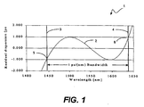
- Fig. I is a graph illustrating the residual dispersion as a function of wavelength in a known transmission fiber that has been compensated by coupling it with a DCF.
- the dispersion of the transmission fiber that has been compensated is 100 ps/nm at 1550 nm.
- the usable bandwidth corresponds to the portion of the curve 2 between the vertical lines 3 and 4.
- the usable bandwidth is defined as the maximal bandwidth where the residual dispersion is within the range of ⁇ 1 ps/nm. At locations 5 and 6 on the curve 2, the residual dispersion falls out of this range.
- the maximal bandwidth for the example shown in Fig. 1 is from approximately 1450 nm to approximately 1650 nm.
- the usable bandwidth for a transmission optical fiber can be increased by coupling it with a DCF+ that has a positive dispersion and a lower RDS than that of the transmission fiber.
- Transmission fibers typically have positive dispersion and positive dispersion slope, and thus a positive RDS. The higher the RDS, the smaller the usable bandwidth.
- Some transmission fibers have very high RDS values, which translates into reduced usable bandwidth. This enables the usable bandwidth of the transmission link to be increased by enabling the RDS value of the transmission link (i.e., the combined transmission fiber and DCF+) to be reduced by combining the transmission fiber with a DCF+ having a positive dispersion and a lower RDS value than the RDS value of the transmission fiber.
- a standard single-mode fiber such as that commonly used as a transmission fiber, has a positive dispersion and a relatively low RDS.
- This type of fiber could be employed as the DCF+ and combined with the actual transmission fiber to reduce the overall RDS of the transmission link comprising transmission fiber and DCF+.
- the present invention is not limited with respect to the type of fiber used for the DCF+ or its dispersion and dispersion slope.
- the present invention also is not limited to any particular transmission fiber.
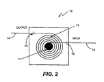
- Fig. 2 illustrates a DCM box 10.
- the DCM box comprises a spool I 1 on which a DCF+ 13 having the properties discussed above (i.e., a lower RDS than that of the transmission fiber).
- the DCF+ 13 is coupled to the transmission fiber 14 at splice locations 15 and 19 by. Because the RDS value of the DCM (i.e., the RDS of the DCF+) is lower than that of the transmission fiber 14, the RDS of the combination of the DCF+ 13 and the transmission fiber 14 is reduced below the RDS of the transmission fiber, which provides the transmission link with a greater usable bandwidth than before being compensated.
- Fig. 3 is a flow chart illustrating a method 20.
- the first step is to obtain the RDS of the transmission fiber, as indicated by block 21.
- a DCF+ is selected that has a positive dispersion and a lower RDS than the RDS of the transmission fiber, as indicated by block 22.
- the DCM that contains the DCF is then connected to the transmission fiber by coupling the ends of the DCF to the transmission fiber in the manner discussed above with reference to Fig. 2. This step is represented by block 23.
- the transmission fiber can also be coupled to a DCM comprising a DCF+ having the properties described above (i.e., having a lower RDS than that of the transmission fiber and which adds positive dispersion to the transmission link) and a negative dispersion compensation fiber (hereinafter "DCF-") with a dispersion of equal amount and opposite sign to that of the combined transmission fiber and the DCF+.
- the DCF- has an RDS that is at least substantially equal (i.e., matched) to that of the combined transmission fiber and DCF+. Therefore, DCF- compensates for the dispersion in the combined transmission fiber and DCF+, thereby increasing the usable bandwidth of the transmission fiber compared to direct dispersion compensation of the transmission fiber by a single DCF-.
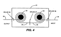
- Fig. 4 illustrates a DCM 31 that comprises first and second spools 32 and 33 on which first and second fibers 34 and 35, respectively, are wound.
- the configuration shown in Fig. 4 enables multiple DCFs to be joined to each other at splice location 37 and to the transmission fiber 36 at splice locations 38 and 39.
- the first DCF+ 34 adds dispersion to the transmission link (transmission fiber and DCF+ 34) and reduces the RDS of the transmission link (by having a lower RDS than that of the transmission fiber).
- the second DCF- compensates the dispersion of the combined DCF+ and transmission fiber. This combination increases the usable bandwidth of the transmission fiber 36 compared to the compensation of the transmission fiber by a single DCF-.
- Fig. 4 is an example of DCM configuration that is suitable for use with the present invention.
- L DCF + ⁇ D transfiber ⁇ L transfiber / D DCF + ⁇ ( RDS DCF ⁇ ⁇ RDS transfiber ) / ( RDS DCF ⁇ ⁇ RDS DCF + )
- L DCF ⁇ ⁇ ( D transfiber ⁇ L transfiber + D DCF + ⁇ L DCF + ) / D DCF ⁇
- L DCF+ is the length of DCF+
- L DCF is the length of DCF-
- D transfiber is the dispersion of the transmission fiber, which is known
- L transfiber is the length of the transmission fiber, which is known
- RDS DCF is the RDS of DCF-, which is known
- RDS transfiber is the RDS of the transmission fiber, which is known
- RDS DCF+ is the RDS of DCF+, which is known.
- the values D transfiber , L transfiber , and RDS transfiber may vary from the actual values of the transmission fiber if that is desirable
Landscapes
- Physics & Mathematics (AREA)
- Electromagnetism (AREA)
- Engineering & Computer Science (AREA)
- Computer Networks & Wireless Communication (AREA)
- Signal Processing (AREA)
- Optical Communication System (AREA)
- Optical Fibers, Optical Fiber Cores, And Optical Fiber Bundles (AREA)
Description
- The present invention relates to optical fibers and, more particularly, to providing dispersion compensation in an optical fiber transmission system over a broad range of wavelengths.
- Dispersion in a glass fiber causes pulse spreading for pulses that include a range of wavelengths, due to the fact that the speed of light in a glass fiber is a function of the transmission wavelength of the light. Pulse broadening is a function of the fiber dispersion, the fiber length and the spectral width of the light source. Dispersion for individual fibers is generally illustrated using a graph having dispersion on the vertical axis (in units of picoseconds (ps) per nanometer (nm), or ps/nm) or ps/nm-km (kilometer) and wavelength on the horizontal axis. There can be both positive and negative dispersion, so the vertical axis may range from, for example, - 250 to + 250 ps.
- For example, typical single mode fibers generally transmit best (i.e., with minimum attenuation) at 1550 nm, whereas dispersion for the same fiber would be approximately zero at 1310 nm. The theoretical minimum loss for glass fiber is approximately 0.16 db/km, and that occurs at the transmission wavelength of about 1550 nm. Because minimum attenuation is prioritized over zero dispersion, the wavelength normally used to transmit over such fibers is typically 1550 nm. Also, Erbium-doped amplifiers, which currently are the most commonly used optical amplifiers for amplifying optical signals carried on a fiber, operate in 1530 to 1565 nm range. Because dispersion for such a fiber normally will not be zero at a transmission wavelength of 1550 nm, attempts are constantly being made to improve dispersion compensation over the transmission path in order to provide best overall system performance (i.e., low optical loss and low dispersion).
- Many techniques have been used for dispersion compensation, including the design and use of dispersion-shifted and dispersion flattened fibers. Dispersion Compensating Modules (DCMs) have also been used in optical communications systems for dispersion compensation, especially in wavelength division multiplexing (WDM) systems. A number of patents describe various uses of DCMs to compensate dispersion including: U.S. Pat. No. 4,261,639 (Kogelnik et al.); U.S. Pat. No. 4,969,710 (Tick et al.); U.S. Pat. No. 5,191,631 (Rosenberg); and U.S. Pat. No. 5,430,822 (Shigematsu et al.). Also, see US 2002/0114597 (Brimacombe et al.). These patents compensate dispersion by inserting DCMs at appropriate intervals along the transmission path. The DCMs usually contain Dispersion Compensating Fiber (DCF) of an appropriate length to produce dispersion of approximate equal magnitude (but opposite sign) to that of the transmission fiber. Also, see WO 02/37718, which discloses an optical link for improving the Q-factor (and thus system performance) of an optical fiber telecommunications system.
- One problem with using the known DCMs to compensate dispersion is that DCF designs generally are sensitive to production tolerances. Therefore, if the DCF design is not highly precise, then when the DCF is combined with the transmission fiber, the resulting transmission link may have too much residual dispersion (i.e., dispersion on wavelength channels other than the center wavelength channel being compensated). This is especially true in broadband communications systems in which transmission rates are very high (e.g., 40 gigabits per second (Gbit/s)). Also, once the DCF is produced, only the length of the DCF can be selected to meet the desired target for dispersion compensation. Moreover, selection of the DCF length (and thus the dispersion of the DCM) should ensure that first order and higher order dispersion are compensated.
- When compensating for higher order dispersion, the Relative Dispersion Slope (RDS) of the transmission fiber should match the RDS of the DCF (and, consequently, of the corresponding DCM). For a given fiber, the RDS is defined as the ratio of the dispersion slope, S, of the fiber to the dispersion, D , of the fiber. Thus, the RDS for a given fiber is equal to S/ D for that fiber. For a DCF combined with a transmission fiber, the total dispersion and the total dispersion slope of the compensated link, D LINK and S LINK , respectively, can be expressed by
Equations 

Equation 1, D TransmFiber corresponds to the dispersion of the transmission fiber, L DCF corresponds to the length of the DCF, and D DCF corresponds to the dispersion of the DCF. InEquations Equation 2, S TransmFiber corresponds to the dispersion slope of the transmission fiber and S DCF corresponds to the dispersion slope of the DCF. - When the dispersion of the system is compensated, i.e., when D Link = 0. the length of DCF needed to compensate for the dispersion of the link can be determined by
Equation 3 as follows:

- It is desirable that the compensated wavelength range be as wide as possible. An inverse relationship exists between the usable bandwidth and the RDS of the transmission fiber. Thus, the RDS of the transmission fiber limits the usable bandwidth of the transmission link.
- It would be desirable to provide a dispersion slope compensation module that increases the usable bandwidth of a dispersion compensated transmission fiber, compared to the usable bandwidth associated with using a single dispersion compensating fiber, especially in cases where the transmission fiber has a high RDS.
- In accordance with the present invention, it has been determined that the usable bandwidth of an optical fiber transmission link can be increased by coupling the transmission fiber of the link with a positive dispersion compensation fiber (hereinafter "DCF+'') that has a positive dispersion and a dispersion slope such that the relative dispersion slope (RDS) of the DCF+ is lower than the RDS of the transmission fiber. Because the RDS of the combination of fibers is lower than the RDS of the transmission fiber, when the transmission link is compensated, there is an increase in the usable bandwidth of the transmission link.
- The present invention provides a dispersion compensation module (DCM) for increasing the usable bandwidth of the optical fiber transmission link after dispersion compensation with negative dispersion compensating fiber. The DCM comprises at least one DCF+ that has an RDS that is lower than the RDS of the transmission fiber. When the DCM is coupled to the transmission fiber, the DCF+ adds an amount of positive dispersion. Because the RDS of the transmission fiber is higher than that of the DCF+, the overall RDS of the transmission link is lowered below that of the transmission fiber, which results in more usable bandwidth for the transmission link when it is compensated.
- The present invention also provides a DCM that contains both a DCF+ as described above and negative dispersion compensation fiber (hereinafter a "DCF-") with a dispersion of equal amount and opposite sign to that of the combined transmission fiber and DCF+. The DCF- has an RDS that is at least substantially equal to that of the combined transmission fiber and DCF+.
- These and other features and advantages of the present invention will become apparent from the following description, drawings and claims.
-
- Fig. 1 is a graph illustrating the residual dispersion as a function of wavelength in a known transmission fiber that has been compensated by coupling it with a DCF-; The dispersion of the transmission fiber that has been compensated in this example is 100 ps/nm at 1550 nm.
- Fig. 2 is a dispersion compensation module (DCM) comprising a DCF+ for increasing the usable bandwidth of the transmission link.
- Fig. 3 is a flow chart illustrating the method of the present invention in accordance with an example embodiment.
- Fig. 4 is a top view of another dispersion compensation module (DCM) comprising DCF+ and DCF- for compensating dispersion in a transmission fiber while increasing the usable bandwidth of the transmission link compared to compensation with a single DCF-.
- Fig. I is a graph illustrating the residual dispersion as a function of wavelength in a known transmission fiber that has been compensated by coupling it with a DCF. The dispersion of the transmission fiber that has been compensated is 100 ps/nm at 1550 nm. The usable bandwidth corresponds to the portion of the
curve 2 between thevertical lines locations curve 2, the residual dispersion falls out of this range. The maximal bandwidth for the example shown in Fig. 1 is from approximately 1450 nm to approximately 1650 nm. - As stated above, it has been determined that the usable bandwidth for a transmission optical fiber can be increased by coupling it with a DCF+ that has a positive dispersion and a lower RDS than that of the transmission fiber. Transmission fibers typically have positive dispersion and positive dispersion slope, and thus a positive RDS. The higher the RDS, the smaller the usable bandwidth. Some transmission fibers have very high RDS values, which translates into reduced usable bandwidth. This enables the usable bandwidth of the transmission link to be increased by enabling the RDS value of the transmission link (i.e., the combined transmission fiber and DCF+) to be reduced by combining the transmission fiber with a DCF+ having a positive dispersion and a lower RDS value than the RDS value of the transmission fiber.
- For example, a standard single-mode fiber, such as that commonly used as a transmission fiber, has a positive dispersion and a relatively low RDS. This type of fiber could be employed as the DCF+ and combined with the actual transmission fiber to reduce the overall RDS of the transmission link comprising transmission fiber and DCF+. The present invention is not limited with respect to the type of fiber used for the DCF+ or its dispersion and dispersion slope. The present invention also is not limited to any particular transmission fiber.
- Fig. 2 illustrates a
DCM box 10. The DCM box comprises a spool I 1 on which a DCF+ 13 having the properties discussed above (i.e., a lower RDS than that of the transmission fiber). TheDCF+ 13 is coupled to thetransmission fiber 14 atsplice locations transmission fiber 14, the RDS of the combination of theDCF+ 13 and thetransmission fiber 14 is reduced below the RDS of the transmission fiber, which provides the transmission link with a greater usable bandwidth than before being compensated. - Fig. 3 is a flow chart illustrating a
method 20. The first step is to obtain the RDS of the transmission fiber, as indicated byblock 21. Once the RDS is obtained, a DCF+ is selected that has a positive dispersion and a lower RDS than the RDS of the transmission fiber, as indicated byblock 22. The DCM that contains the DCF is then connected to the transmission fiber by coupling the ends of the DCF to the transmission fiber in the manner discussed above with reference to Fig. 2. This step is represented byblock 23. - The transmission fiber can also be coupled to a DCM comprising a DCF+ having the properties described above (i.e., having a lower RDS than that of the transmission fiber and which adds positive dispersion to the transmission link) and a negative dispersion compensation fiber (hereinafter "DCF-") with a dispersion of equal amount and opposite sign to that of the combined transmission fiber and the DCF+. The DCF- has an RDS that is at least substantially equal (i.e., matched) to that of the combined transmission fiber and DCF+. Therefore, DCF- compensates for the dispersion in the combined transmission fiber and DCF+, thereby increasing the usable bandwidth of the transmission fiber compared to direct dispersion compensation of the transmission fiber by a single DCF-. An example embodiment for implementing this multi-DCF solution will now be discussed with reference to Fig. 4.
- Fig. 4 illustrates a
DCM 31 that comprises first andsecond spools second fibers splice location 37 and to thetransmission fiber 36 atsplice locations first DCF+ 34 adds dispersion to the transmission link (transmission fiber and DCF+ 34) and reduces the RDS of the transmission link (by having a lower RDS than that of the transmission fiber). The second DCF- compensates the dispersion of the combined DCF+ and transmission fiber. This combination increases the usable bandwidth of thetransmission fiber 36 compared to the compensation of the transmission fiber by a single DCF-. Fig. 4 is an example of DCM configuration that is suitable for use with the present invention. - The lengths of the DCFs can be obtained from the following equations:


where LDCF+ is the length of DCF+, LDCF, is the length of DCF-, Dtransfiber is the dispersion of the transmission fiber, which is known, Ltransfiber is the length of the transmission fiber, which is known, RDSDCF is the RDS of DCF-, which is known, RDStransfiber is the RDS of the transmission fiber, which is known, and RDSDCF+ is the RDS of DCF+, which is known. The values Dtransfiber, Ltransfiber, and RDStransfiber may vary from the actual values of the transmission fiber if that is desirable for the amount of dispersion of the transmission fiber that shall be compensated. - It should be noted that the above-described embodiment, of the present invention is an example of implementation. Those skilled in the art will understand from the disclosure provided herein that many variations and modifications may be made to the embodiment described without departing from the scope of the present invention. All such modifications and variations are within the scope of the present invention.
Claims (6)
- An optical fiber transmission link (34, 36) designed to have increased usable bandwidth, the optical fiber transmission link (34, 36) comprising a transmission fiber (36) and at least a first dispersion compensating fiber (34), DCF1,
wherein the first dispersion compensating fiber (34) DCF1, has a dispersion, D1, a dispersion slope, S1, and a relative dispersion slope, RDS1, the transmission fiber (36) having a dispersion, D TransFiber , a dispersion slope, S TransFiber , and a relative dispersion slope, RDS TransFiber , and wherein RDS1 is less than RDS TransFiber ,
the first dispersion compensating fiber (34) DCF1 being coupled with the transmission fiber (36) to form the transmission link (34, 36), the transmission link (34, 36) having a relative dispersion slope, RDS Trans.link , that is less than RDS TransFiber ,
characterized by
a second dispersion compensating fiber (35), DCF2, having a relative dispersion slope, RDS2, that is substantially equal to the relative dispersion slope RDS Trans.link of the transmission fiber (36), being coupled to the first dispersion compensating fiber (34) DCF1, the second dispersion compensating fiber DCF2 compensating the dispersion in a portion of the transmission link (34, 36) comprising the transmission fiber coupled to the first dispersion compensating fiber (34) DCF1. - The optical fiber transmission link (34, 36) of claim 1, wherein the relative dispersion slope RDS1 of the first dispersion compensating fiber (34) is selected to be lower than the relative dispersion slope RDS Trans.Fiber of the transmission fiber (36), in order to decrease the relative dispersion slope of the transmission link (34, 36) RDS Trans.link .
- The optical transmission link (34, 36) of claim 1, wherein the dispersion slope S1 of the first dispersion compensating fiber (34) DCF1 is a relatively small, positive dispersion slope.
- The optical transmission link (34, 36) of claim 1, wherein the dispersion slope S1 of the first dispersion compensating fiber (34) DCF1 is negative.
- The optical transmission link (34, 36) of claim 1, wherein the dispersion D1 of the first dispersion compensating fiber (34) DCF1 is positive.
- A method for performing dispersion compensation while increasing the usable bandwidth of a transmission link, the method comprising the steps of:selecting at least a first dispersion compensating fiber (34), DCF1, to be coupled with a transmission fiber (36), wherein the first dispersion compensating fiber (34) DCF1 has a dispersion, D1, a dispersion slope, S1, and a relative dispersion slope, RDS1, the transmission fiber (36) having a dispersion, D, a dispersion slope, S , and a relative dispersion slope, RDS TransFiber , and wherein the first dispersion compensating fiber (34) DCF1 is selected so that the relative dispersion slope RDS1 of the first dispersion compensating fiber (34) is less than the relative dispersion slope RDS TransFiber of the transmission fiber (36);coupling a first end of the first dispersion compensating fiber (34) DCF1 with the transmission fiber (36) to form a transmission link (34, 36), the transmission link (34, 36) having a relative dispersion slope RDS Translink , and wherein RDS Translink is less than RDS TransFiber ,characterized in that the method further comprises the steps of:selecting a second dispersion compensating fiber (35), DCF2, having a negative dispersion D2 , a dispersion slope, S2, and a relative dispersion slope DCF2; andcoupling a first end of the second dispersion compensation fiber DCF2 (35) to a second end of the first dispersion compensating fiber (34) DCF1, wherein the relative dispersion slope RDS2 of the second dispersion compensation fiber is substantially equal to the relative dispersion slope RDS Translink of the transmission link (34, 36);wherein the transmission fiber (36) has a length L TransFiber , and wherein lengths L1 and L2 of the first dispersion compensating fiber (34) DCF1 and of the second dispersion compensating fiber (35) DCF2, respectively, that are combined with the transmission fiber (36) and with the second dispersion compensating fiber (35) DCF2, respectively are defined by:


Applications Claiming Priority (2)
| Application Number | Priority Date | Filing Date | Title |
|---|---|---|---|
| US237002 | 2002-09-06 | ||
| US10/237,002 US6823123B2 (en) | 2002-09-06 | 2002-09-06 | Method and apparatus for providing dispersion compensation |
Publications (2)
| Publication Number | Publication Date |
|---|---|
| EP1396952A1 EP1396952A1 (en) | 2004-03-10 |
| EP1396952B1 true EP1396952B1 (en) | 2006-04-12 |
Family
ID=31715329
Family Applications (1)
| Application Number | Title | Priority Date | Filing Date |
|---|---|---|---|
| EP03010412A Expired - Lifetime EP1396952B1 (en) | 2002-09-06 | 2003-05-08 | Method and apparatus for providing dispersion compensation |
Country Status (5)
| Country | Link |
|---|---|
| US (1) | US6823123B2 (en) |
| EP (1) | EP1396952B1 (en) |
| JP (1) | JP3872048B2 (en) |
| CN (1) | CN1225661C (en) |
| DE (1) | DE60304524T2 (en) |
Families Citing this family (4)
| Publication number | Priority date | Publication date | Assignee | Title |
|---|---|---|---|---|
| US7194171B2 (en) * | 1999-07-19 | 2007-03-20 | Sumitomo Electric Industries, Ltd. | Dispersion compensating optical fiber, dispersion compensating device, optical transmission line and optical transmission system |
| JP4699751B2 (en) * | 2004-12-27 | 2011-06-15 | 株式会社日立製作所 | Dispersion compensation device |
| US7412125B2 (en) * | 2005-04-28 | 2008-08-12 | Tellabs Operations, Inc. | Optical dispersion compensation |
| EP2286284B1 (en) * | 2008-05-30 | 2015-05-06 | Koninklijke Philips N.V. | A higher order dispersion compensation device |
Family Cites Families (11)
| Publication number | Priority date | Publication date | Assignee | Title |
|---|---|---|---|---|
| US4261639A (en) * | 1979-11-13 | 1981-04-14 | Bell Telephone Laboratories, Incorporated | Optical pulse equalization in single-mode fibers |
| JP2636876B2 (en) * | 1988-04-08 | 1997-07-30 | 日本電信電話株式会社 | Optical fiber dispersion compensator |
| US5191631A (en) * | 1991-12-19 | 1993-03-02 | At&T Bell Laboratories | Hybrid optical fiber and method of increasing the effective area of optical transmission using same |
| US5361319A (en) * | 1992-02-04 | 1994-11-01 | Corning Incorporated | Dispersion compensating devices and systems |
| JP2760233B2 (en) * | 1992-09-29 | 1998-05-28 | 住友電気工業株式会社 | Optical communication device |
| MY132931A (en) * | 1998-05-01 | 2007-10-31 | Corning Inc | Dispersion managed optical waveguide and system with distributed amplification |
| US6574037B2 (en) * | 1998-06-16 | 2003-06-03 | Xtera Communications, Inc. | All band amplifier |
| US6366728B1 (en) * | 2000-01-28 | 2002-04-02 | Mci Worldcom, Inc. | Composite optical fiber transmission line method |
| US6584262B1 (en) | 2000-11-06 | 2003-06-24 | Tyco Telecommunications (Us) Inc. | Method and apparatus for the optimization of dispersion map using slope-compensating optical fibers |
| US20020114597A1 (en) * | 2000-12-26 | 2002-08-22 | Nortel Networks Limited | Method and apparatus for reducing dispersion slope in optical transmission fibre systems |
| US6724956B2 (en) * | 2002-04-03 | 2004-04-20 | Fitel Usa Corporation | Method and apparatus for providing dispersion compensation |
-
2002
- 2002-09-06 US US10/237,002 patent/US6823123B2/en not_active Expired - Lifetime
-
2003
- 2003-05-08 DE DE60304524T patent/DE60304524T2/en not_active Expired - Lifetime
- 2003-05-08 EP EP03010412A patent/EP1396952B1/en not_active Expired - Lifetime
- 2003-06-05 CN CNB031411762A patent/CN1225661C/en not_active Expired - Fee Related
- 2003-09-05 JP JP2003313372A patent/JP3872048B2/en not_active Expired - Fee Related
Also Published As
| Publication number | Publication date |
|---|---|
| CN1225661C (en) | 2005-11-02 |
| JP2004104786A (en) | 2004-04-02 |
| EP1396952A1 (en) | 2004-03-10 |
| US20040047574A1 (en) | 2004-03-11 |
| JP3872048B2 (en) | 2007-01-24 |
| US6823123B2 (en) | 2004-11-23 |
| CN1480748A (en) | 2004-03-10 |
| DE60304524T2 (en) | 2006-08-24 |
| DE60304524D1 (en) | 2006-05-24 |
Similar Documents
| Publication | Publication Date | Title |
|---|---|---|
| JP3516409B2 (en) | Wavelength division multiplex optical waveguide system | |
| EP1149479B1 (en) | Optical system and method having low loss and non-linear effects | |
| US6684016B2 (en) | Optical fiber for wavelength division multiplexing optical transmission system using densely spaced optical channels | |
| US7164829B2 (en) | Optical fiber, optical transmission line and optical communications system | |
| US6587627B2 (en) | Dispersion-compensating fiber, and dispersion-compensating module and hybrid optical fiber link using the same | |
| US7027698B2 (en) | Optical fiber for WDM transmission | |
| US6917743B2 (en) | Optical fiber, optical transmission line, and optical communications system | |
| EP1297645B1 (en) | Apparatus for the optimization of dispersion map using slope compensating optical fibers | |
| US6823123B2 (en) | Method and apparatus for providing dispersion compensation | |
| US6724956B2 (en) | Method and apparatus for providing dispersion compensation | |
| EP1298821B1 (en) | Optical transmission system using dispersion compensating fibers | |
| CA2430007A1 (en) | Dispersion managed optical fiber and system | |
| US6873798B1 (en) | Method and apparatus for optimizing the dispersion and dispersion slope for a dispersion map with slope-compensating optical fibers | |
| US6999666B2 (en) | Fibre for compensation of the cumulative chromatic dispersion in a fibre with negative chromatic dispersion | |
| EP1259840B1 (en) | Optical fiber for wdm transmission | |
| US6826340B2 (en) | Optical pulse transmission lines | |
| EP1531349A1 (en) | Chromatic dispersion compensation module | |
| US20030108313A1 (en) | Optical fiber transmission line, optical cable, and optical transmission system | |
| EP1208395A2 (en) | Fiber optic cable for increased transmission capacity and wavelength division multiplexing optical transmission system using the same | |
| US20040033015A1 (en) | Dispersion compensation module comprising a single spool on which multiple optical fibers are wound | |
| EP1653262A2 (en) | Optical system and method having low loss and non-linear effects | |
| EP0887956A1 (en) | Optical telecommunications system with chromatic dispersion compensator | |
| JP2004004937A (en) | Fiber optic cable |
Legal Events
| Date | Code | Title | Description |
|---|---|---|---|
| PUAI | Public reference made under article 153(3) epc to a published international application that has entered the european phase |
Free format text: ORIGINAL CODE: 0009012 |
|
| 17P | Request for examination filed |
Effective date: 20030508 |
|
| AK | Designated contracting states |
Kind code of ref document: A1 Designated state(s): AT BE BG CH CY CZ DE DK EE ES FI FR GB GR HU IE IT LI LU MC NL PT RO SE SI SK TR |
|
| AX | Request for extension of the european patent |
Extension state: AL LT LV MK |
|
| 17Q | First examination report despatched |
Effective date: 20040130 |
|
| AKX | Designation fees paid |
Designated state(s): DE FR GB |
|
| GRAP | Despatch of communication of intention to grant a patent |
Free format text: ORIGINAL CODE: EPIDOSNIGR1 |
|
| GRAS | Grant fee paid |
Free format text: ORIGINAL CODE: EPIDOSNIGR3 |
|
| GRAA | (expected) grant |
Free format text: ORIGINAL CODE: 0009210 |
|
| AK | Designated contracting states |
Kind code of ref document: B1 Designated state(s): DE FR GB |
|
| REG | Reference to a national code |
Ref country code: GB Ref legal event code: FG4D |
|
| REF | Corresponds to: |
Ref document number: 60304524 Country of ref document: DE Date of ref document: 20060524 Kind code of ref document: P |
|
| ET | Fr: translation filed | ||
| PLBE | No opposition filed within time limit |
Free format text: ORIGINAL CODE: 0009261 |
|
| STAA | Information on the status of an ep patent application or granted ep patent |
Free format text: STATUS: NO OPPOSITION FILED WITHIN TIME LIMIT |
|
| 26N | No opposition filed |
Effective date: 20070115 |
|
| REG | Reference to a national code |
Ref country code: FR Ref legal event code: PLFP Year of fee payment: 14 |
|
| PGFP | Annual fee paid to national office [announced via postgrant information from national office to epo] |
Ref country code: DE Payment date: 20160527 Year of fee payment: 14 |
|
| REG | Reference to a national code |
Ref country code: FR Ref legal event code: PLFP Year of fee payment: 15 |
|
| REG | Reference to a national code |
Ref country code: DE Ref legal event code: R119 Ref document number: 60304524 Country of ref document: DE |
|
| PG25 | Lapsed in a contracting state [announced via postgrant information from national office to epo] |
Ref country code: DE Free format text: LAPSE BECAUSE OF NON-PAYMENT OF DUE FEES Effective date: 20171201 |
|
| REG | Reference to a national code |
Ref country code: FR Ref legal event code: PLFP Year of fee payment: 16 |
|
| PGFP | Annual fee paid to national office [announced via postgrant information from national office to epo] |
Ref country code: FR Payment date: 20210525 Year of fee payment: 19 |
|
| PGFP | Annual fee paid to national office [announced via postgrant information from national office to epo] |
Ref country code: GB Payment date: 20210527 Year of fee payment: 19 |
|
| GBPC | Gb: european patent ceased through non-payment of renewal fee |
Effective date: 20220508 |
|
| PG25 | Lapsed in a contracting state [announced via postgrant information from national office to epo] |
Ref country code: FR Free format text: LAPSE BECAUSE OF NON-PAYMENT OF DUE FEES Effective date: 20220531 |
|
| PG25 | Lapsed in a contracting state [announced via postgrant information from national office to epo] |
Ref country code: GB Free format text: LAPSE BECAUSE OF NON-PAYMENT OF DUE FEES Effective date: 20220508 |