EP1396760A2 - Differential pumping system and exposure apparatus - Google Patents
Differential pumping system and exposure apparatus Download PDFInfo
- Publication number
- EP1396760A2 EP1396760A2 EP03255468A EP03255468A EP1396760A2 EP 1396760 A2 EP1396760 A2 EP 1396760A2 EP 03255468 A EP03255468 A EP 03255468A EP 03255468 A EP03255468 A EP 03255468A EP 1396760 A2 EP1396760 A2 EP 1396760A2
- Authority
- EP
- European Patent Office
- Prior art keywords
- light
- chamber
- differential pumping
- pumping system
- optical system
- Prior art date
- Legal status (The legal status is an assumption and is not a legal conclusion. Google has not performed a legal analysis and makes no representation as to the accuracy of the status listed.)
- Withdrawn
Links
Images




Classifications
-
- G—PHYSICS
- G03—PHOTOGRAPHY; CINEMATOGRAPHY; ANALOGOUS TECHNIQUES USING WAVES OTHER THAN OPTICAL WAVES; ELECTROGRAPHY; HOLOGRAPHY
- G03F—PHOTOMECHANICAL PRODUCTION OF TEXTURED OR PATTERNED SURFACES, e.g. FOR PRINTING, FOR PROCESSING OF SEMICONDUCTOR DEVICES; MATERIALS THEREFOR; ORIGINALS THEREFOR; APPARATUS SPECIALLY ADAPTED THEREFOR
- G03F7/00—Photomechanical, e.g. photolithographic, production of textured or patterned surfaces, e.g. printing surfaces; Materials therefor, e.g. comprising photoresists; Apparatus specially adapted therefor
- G03F7/70—Microphotolithographic exposure; Apparatus therefor
- G03F7/708—Construction of apparatus, e.g. environment aspects, hygiene aspects or materials
- G03F7/70808—Construction details, e.g. housing, load-lock, seals or windows for passing light in or out of apparatus
- G03F7/70841—Constructional issues related to vacuum environment, e.g. load-lock chamber
-
- G—PHYSICS
- G03—PHOTOGRAPHY; CINEMATOGRAPHY; ANALOGOUS TECHNIQUES USING WAVES OTHER THAN OPTICAL WAVES; ELECTROGRAPHY; HOLOGRAPHY
- G03F—PHOTOMECHANICAL PRODUCTION OF TEXTURED OR PATTERNED SURFACES, e.g. FOR PRINTING, FOR PROCESSING OF SEMICONDUCTOR DEVICES; MATERIALS THEREFOR; ORIGINALS THEREFOR; APPARATUS SPECIALLY ADAPTED THEREFOR
- G03F7/00—Photomechanical, e.g. photolithographic, production of textured or patterned surfaces, e.g. printing surfaces; Materials therefor, e.g. comprising photoresists; Apparatus specially adapted therefor
- G03F7/70—Microphotolithographic exposure; Apparatus therefor
- G03F7/708—Construction of apparatus, e.g. environment aspects, hygiene aspects or materials
- G03F7/70908—Hygiene, e.g. preventing apparatus pollution, mitigating effect of pollution or removing pollutants from apparatus
- G03F7/70916—Pollution mitigation, i.e. mitigating effect of contamination or debris, e.g. foil traps
Definitions
- the present invention relates to a light source and an illumination system for use with an extreme ultraviolet (“EUV”) exposure apparatus that transfers a fine pattern in semiconductor manufacturing.
- EUV extreme ultraviolet
- a reduction projection exposure apparatus In manufacturing such a fine semiconductor device as a semiconductor memory and a logic circuit in photolithography technology, a reduction projection exposure apparatus has been conventionally employed which uses a projection optical system to project a circuit pattern formed on a mask (reticle) onto a wafer, etc. to transfer the circuit pattern.
- the minimum critical dimension to be transferred by the projection exposure apparatus or resolution is proportionate to a wavelength of light used for exposure, and inversely proportionate to the numerical aperture ("NA") of the projection optical system.
- NA numerical aperture
- a shorter wavelength of ultraviolet light has been promoted from an ultra-high pressure mercury lamp (such as i-line with a wavelength of approximately 365 nm) to KrF excimer laser (with a wavelength of approximately 248 nm) and ArF excimer laser (with a wavelength of approximately 193 nm).
- the photolithography using the ultraviolet light has the limit to satisfy the rapidly promoting fine processing of a semiconductor device, and a reduction projection optical apparatus using the EUV light with a wavelength of 10 to 15 nm shorter than that of the ultraviolet light (referred to as "EUV exposure apparatus") has been developed to efficiently transfer a very fine circuit pattern of 0.1 ⁇ m or less.
- EUV exposure apparatus a reduction projection optical apparatus using the EUV light with a wavelength of 10 to 15 nm shorter than that of the ultraviolet light
- the EUV light source uses, for example, a laser plasma light source. It irradiates a highly intensified pulse laser beam to a target material put in a vacuum chamber to generate high-temperature plasma for use as the EUV light with a wavelength of about 13 nm emitted from this.
- the target material may use Xe gas, droplets, and clusters, and a metallic thin film, such as copper, tin, aluminum, etc., and is supplied to the vacuum chamber by gas jetting means and other means.
- the laser plasma as one mode of the EUV light source irradiates the high-strength pulse laser light onto the target material and generates not only the EUV light from the target material, but also flying particles called debris, which causes pollution, damages and lowered reflectance of an optical element. Accordingly, a method have been conventionally proposed which mitigates influence of debris by providing a foil trap made of a porous material around the target material and circulating inert gas, such as He gas, as buffer gas.
- the pressure in a vacuum chamber becomes about 10 Pa although a vacuum pump exhausts the chamber.
- the atmosphere of a stage subsequent to the light emitting section should be maintained as clean as possible, preferably with the degree of vacuum of about 10 -7 Pa, for intended performance such as reflectance of the optical element, since the EUV light has low transmittance to the air and contaminates an optical element when reacted with a residual gas component (such as high molecule organic gas).
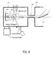
- FIG. 8 is a schematic structure of an EUV light source 3000 that uses a laser plasma light source.
- the differential pumping using the orifice generates a pressure difference of about 10 -2 Pa between the light source chamber 3110 and an illumination system chamber 3120.
- the pressure in the illumination system 3120 becomes about 10 -1 Pa, which is insufficient to maintain the performance such as the reflectance of the optical element 3500.
- a spheroid condenser mirror 3600 should capture the EUV light generated from the target material as much as possible, for example, at about ⁇ steradian. However, as the capture angle becomes large, it becomes difficult to elongate the channel 3900 and to obtain a desired pressure difference.
- a demand to maintain the pressure in the illumination system chamber to be the degree of vacuum of about 10 -7 Pa is common to a discharge method that generates the EUV light by circulating Xe gas, etc. in an electrode for discharging and generating plasma, as well as the laser plasma method.
- an embodiment of the present invention seeks to provide a differential pumping system that has high differential pumping capacity without harming use efficiency of the EUV, and maintain performance of an optical element, such as reflectance.
- a differential pumping system of one aspect according to the present invention includes a first chamber for storing a light source that emits light, a second chamber that receives light from the first chamber, and a vacuum pump, provided between the first and second chambers, which includes a hollow shaft through which the light passes, and exhausts the hollow shaft.
- the vacuum pump may include a vane that rotates around the hollow shaft.
- a wall surface of the hollow shaft may have an aperture, which has a vane section and exhausts gas molecules outside the shaft.
- the differential pumping system may further include a first exhaust unit for exhausting the first chamber, and a second exhaust unit for exhausting the second chamber, wherein pressure of the second chamber is maintained lower than that of the first chamber.
- the light may be collimated and the hollow shaft may have a cylindrical shape. The light may be condensed, and the hollow shaft may be so tapered that a side of the first chamber is narrower than that of the second chambers.
- the differential pumping system may further include another vacuum pump for exhausting an atmosphere to the outside which has been exhausted by the vacuum pump provided between the first and second chambers.
- the light is, for example, EUV light.
- An exposure apparatus of another aspect according to the present invention includes the above differential pumping system, an illumination optical system that introduces the light to a mask that forms a circuit pattern to be transferred onto an object, and a projection optical system that introduces the light from the mask onto the object, wherein the illumination optical system and projection optical system are installed in the second chamber.
- a measurement system of still another aspect according to the present invention includes the above differential pumping system, a light intensity measuring apparatus for measuring light intensity from an object to be measured, an illumination optical system that introduces the light to the object, and a measurement optical system that introduces the light from the object to the light intensity measuring apparatus, wherein the light intensity measuring apparatus, illumination optical system and measurement optical system are installed in the second chamber.
- a device fabrication method of another aspect of this invention includes the steps of exposing a plate by using the above exposure apparatus, and performing a predetermined process for the exposed object. Claims for a device fabrication method for performing operations similar to that of the above exposure apparatus cover devices as intermediate and final products. Such devices include semiconductor chips like an LSI and VLSI, CCDs, LCDs, magnetic sensors, thin film magnetic heads, and the like.
- FIG. 1 is a schematic structure of the differential pumping system of one embodiment according to the present invention.
- the differential pumping system 1 enables the pressure of an illumination system chamber 200 that is connectible to a light source chamber 100, to be smaller than that of the light source chamber 100 that accommodates plasma 106 as a light source for emitting the EUV light 107.
- the differential pumping system 1 is provided with an exhaust part 300 along an optical axis of the EUV light 107, which allows the EUV light 107 to pass to introduce the EUV light 107 to the second chamber 200, and exhausts gas molecules from the light source chamber 100 to the illumination system chamber 200 by exhausting the passage of the EUV light.
- Pulsed laser 101 exited from a laser generator is condensed on a target 105, such as Xe gas, supplied from a nozzle 104 via a condenser lens 102 and a transmission window 103, generating the plasma 106.
- the plasma 106 irradiates the EUV light 107, and a spheroid condenser mirror 108 condenses the EUV light 107 for improved use efficiency, and introduces it into the mirror chamber 150 that accommodates a mirror 151.
- the mirror converts the EUV light 107 into collimated light and introduces the collimated EUV light into a hollow part 312a of a rotational shaft 312, which will be described later.
- the plasma 106 generates not only the EUV light 107 but also flying particles called debris 109, which splashes and causes pollution, damages and lowered reflectance of the neighboring condenser mirror 108 and the mirror 151. Accordingly, a buffer gas supply unit 110 introduces He gas 111 into the light source chamber 100 to reduce splash of the debris 109 using flows of the He gas 111.
- the Xe gas as a target 105 and the He gas 111 as buffer gas are always supplied to the light source chamber 100 while a vacuum pump 113 exhausts the chamber 100. Therefore, the pressure of the light source chamber 100 becomes about 10 Pa. In order to prevent deterioration of the mirror 151, the pressure of the mirror chamber 150 should preferably low. Accordingly, an orifice is provided at a connection part with the light source chamber 100 and a pump 152.
- An exhaust part 300 is implemented as a turbo molecular pump 310 having a rotational shaft 312 having a hollow part 312a through which the EUV light 107 passes so that an optical axis of the EUV light 107 is not shielded.
- a stator 314 is fixed onto the turbo molecular pump 310.
- the rotary shaft 312 has vanes 312b around the shaft, which has a blade section and exhausts gas molecules outside the rotational shaft 312.
- a roughing pump 320 exhausts gas compressed by the turbo molecular pump.
- the EUV light 107 should be thin in order to further enhance the differential pumping performance of the turbo molecular pump 310, and it is preferable to maintain the low pressure environment of the illumination system chamber 200 and arrange the illumination system chamber 200 close to the light source chamber 100 to prevent pollution and damages of the optical elements 201 and 202 housed in the illumination system chamber 200.
- the illumination system chamber 200 is always exhausted by a vacuum pump 203.
- FIG. 2 is a schematic structure of one example of the rotational shaft 312 of the turbo molecular pump 310.
- An aperture for exhausting gas molecules to outside is provided in a wall surface of the rotational shaft 312 that includes the hollow part 312a and the vanes 312b are formed on a wall surface of the aperture.
- the rotational shaft 312 and the vanes 312b rotate at a high speed in an arrow direction shown in FIG. 2.
- the gas molecules AM that has entered the hollow part 312a in the rotational shaft 312 collide with the vanes 312b and scattered in a radial direction as shown by arrows in FIG. 2.
- the compressed gas molecules AM are exhausted to the outside by the roughing pump 320 as exhaust means.
- the scattered gas molecules AM passes through a section of the rotational shaft 312 and are exhausted to the outside of the rotational shaft 312.
- the stators 314 and rotors 316 that may rotate around the rotational shaft 312 compress the gas molecules AM in the roughing pump 320.
- the compressed gas molecules AM are exhausted to the outside by the roughing pump 320 as exhaust means.
- the rotational shaft 312 may include vanes 312c in the hollow part 312a, which exhaust the gas molecules AM to the outside of the rotational shaft 312.
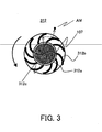
- FIG. 3 is a schematic structure of one example of the rotational shaft 312 of the turbo molecular pump 310.
- the vanes 312c shield the EUV light 107 but maintains its sectional area as small as possible so as not to reduce the use efficiency of the EUV light 107.
- the rotational shaft 312, and vanes 312b and 312c rotate at a high speed in an arrow direction shown in FIG. 3. Therefore, the gas molecules AM that move approximately parallel to the optical axis of the EUV light 107 collide with the vanes 312c and are scattered in a radial direction as shown by arrows in FIG. 3.
- the scattered gas molecules AM are further scattered by the vanes 312b, pass the section of the rotational shaft 312, and are exhausted outside the rotational shaft 312, providing the higher differential pumping performance.
- the differential pumping performance will now be calculated when the exhaust part 300 (or turbo molecular pump 310) is applied. For simplicity purposes, it is assumed that there is no roughing pump 320 provided in the exhaust part 300.
- p1 (Pa) is the pressure of the mirror chamber 150
- p2 (Pa) is the pressure of the illumination system chamber 200
- S1 (m 3 / s) is a pumping speed at which the vacuum pump 152 exhausts the mirror chamber 150
- S2 (m 3 / s) is a pumping speed at which the vacuum pump 203 exhausts the illumination system chamber 200
- S12 (m 3 / s) is a pumping speed at which the turbo molecular pump 310 that connects the mirror chamber 150 and the illumination system chamber 200
- Q1 (Pa ⁇ m 3 / s) is degas amount generated from the mirror chamber 150
- Q2 (Pa ⁇ m 3 / s) is degas amount generated from the illumination system chamber 200
- Q10 (Pa ⁇ m 3 / s) and Q20 (Pa ⁇ m 3 / s) are flow rate exhausted by respective vacuum pumps 152 and 203
- the turbo molecular pump 310 uses the rotational shaft that has the hollow part 312a so as not to shield the optical axis of the EUV light 107 as illumination light, the differential pumping performance may improve and prevent pollution and deterioration of the optical elements 201 and 202 housed in the illumination system chamber 200.
- the differential pumping system 1 is useful for applications using a point source X ray source, such as a reflectometer, a wave front measurement device, a microscope, a shape measurement device, medical equipment, a chemical composition analyzer, and a structural analyzer.
- a point source X ray source such as a reflectometer, a wave front measurement device, a microscope, a shape measurement device, medical equipment, a chemical composition analyzer, and a structural analyzer.
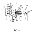
- FIG. 4 is a schematic structure of the differential pumping system 1A of one embodiment according to the present invention.
- the differential pumping system 1A is similar to the differential pumping system 1, but different from it in an exhaust part 400.
- the differential pumping system 1A provides the exhaust part 400 between the light source chamber 100 and the illumination system chamber 200.
- the EUV light 107 is incident upon the illumination system chamber 200 once condensed by the condenser mirror 108.
- the exhaust part 400 is implemented as a turbo molecular pump 310 having a rotational axis 412 having a hollow part 312a that opens like a taper corresponding to a collection angle of the EUV light 107 so as not to prevent the EUV light 107 from passing.
- the pressure of the light source chamber 100 corresponds to a molecular flow region, and thus it is effective that the hollow part 412a has the smallest opening at a side of the light source chamber 100.
- a position of a condensed point 107a of the EUV light 107 corresponds to the opening of the hollow part 412a closest to the light source chamber 100.
- the turbo molecular pump 410 fixes stators 414.
- the rotational shaft 412 has vanes 412b around it, which have a blade section and exhaust gas molecules to the outside of the rotational shaft 412.
- the roughing pump 420 exhausts the gas compressed by the turbo molecular pump 410.
- Such a configuration may provide the differential pressure between the light source chamber 100 and the illumination system chamber 200, and reduces the pressure of the entire illumination system chamber 200. Therefore, it is possible to prevent pollution and deterioration of all the optical elements housed in the illumination system mirror 200.
- FIG. 5 is a schematic structure of the exposure apparatus 800 of one embodiment.
- the exposure apparatus 800 is a projection exposure apparatus that uses EUV light with a wavelength of 13.4 nm as exposure light for step-and-scan or step-and-repeat exposure of a circuit pattern formed on the mask 820 onto an object 840 to be exposed.
- This exposure apparatus is suitable for a lithography process less than submicron or quarter micron, and the present embodiment uses the step-and-scan exposure apparatus (also referred to as a "scanner") as an example.
- the "step-and-scan manner" is an exposure method that exposes a mask pattern onto a wafer by continuously scanning the wafer relative to the mask, and by moving, after a shot of exposure, the wafer stepwise to the next exposure area to be shot.
- the "step-and-repeat manner" is another mode of exposure method that moves a wafer stepwise to an exposure area for the next shot every shot of cell projection onto the wafer.
- the exposure apparatus 800 includes an illumination apparatus 810, a:mask 820, a mask stage 825 that mounts the mask 820, a projection optical system 830, an object to be exposed 840, a wafer stage 845 that mounts the object 840, an alignment detecting mechanism 850, and a focus position detecting mechanism 860.
- the illumination apparatus 810 uses arc-shaped EUV light, for example, with a wavelength of 13.4 corresponding to an arc-shaped field of the projection optical system 830 to illuminate the mask 820, and includes an EUV light source 812 and illumination optical system 814.
- the differential pumping system 1 or 1A is applicable to a connection between the EUV light source 812 and the illumination optical system 814 of the subsequent stage in the illumination apparatus 810, and the differential pumping system 1 or 1A may maintain performance, such as reflectance of an optical element of the illumination optical system 814 in a low pressure atmosphere for the illumination optical system 814 without damaging use efficiency of the EUV light.
- the EUV light source 812 may use any of the above structures, and a detailed description will be omitted.
- the illumination optical system 814 includes a condenser mirror 814a, an optical integrator 814b, etc.
- the condenser mirror 814a serves to collect the EUV light that is isotropically irradiated from the laser plasma.
- the optical integrator 814b serves to uniformly illuminate the mask 820 with a predetermined NA. An aperture to limit the illumination area to an arc shape is also provided.
- the mask 820 is a reflection-type mask that forms a circuit pattern or image to be transferred, and supported and driven by the mask stage 825.
- the diffracted light from the mask 820 is reflected by the projection optical system 830 and projected onto the object 840.
- the mask 820 and the object 840 are arranged in an optically conjugate relationship.
- the exposure apparatus 800 is a step-and-scan exposure apparatus, and projects a reduced size of the pattern on the mask 820 on the object 840 by scanning the mask 820 and the object 840.
- the mask stage 825 supports the mask 820 and is connected to a moving mechanism (not shown).
- the mask stage 825 may use any structure known in the art.
- a moving mechanism (not shown) may include a linear motor etc., and drives the mask stage 825 at least in a direction X and moves the mask 820.
- the exposure apparatus 800 synchronously scans the mask 820 and the object 840.
- the exposure apparatus 800 assigns the direction X to scan the mask 820 or the object 840, a direction Y perpendicular to the direction X, and a direction Z perpendicular to the mask 820 or the object 840.
- the projection optical system 830 uses plural multilayer mirrors 830a to project a reduced size of a pattern formed on the mask 820 onto the object 840.
- the number of mirrors is about four to six.
- the mask 820 and object 840 are simultaneously scanned to transfer a wide area that is an arc-shaped area or ring field apart from the optical axis by a predetermined distance.
- the projection optical system 830 has a NA of about 0.1 to 0.3.
- a photoresist application step includes a pretreatment, an adhesion accelerator application treatment, a photoresist application treatment, and a pre-bake treatment.
- the pretreatment includes cleaning, drying, etc.
- the adhesion accelerator application treatment is a surface reforming process so as to enhance the adhesion between the photoresist and a base (i.e., a process to increase the hydrophobicity by applying a surface active agent), through a coat or vaporous process using an organic film such as HMDS (Hexamethyl-disilazane).
- the pre-bake treatment is a baking (or burning) step, softer than that after development, which removes the solvent.
- An object to be exposed 840 is held onto the wafer stage 845 by a wafer chuck.
- the wafer stage 845 moves the object 840, for example, using a linear motor in XYZ directions.
- the mask 820 and the object 840 are synchronously scanned.
- the positions of the mask stage 825 and wafer stage 845 are monitored, for example, by a laser interferometer, and driven at a constant speed ratio.
- the alignment detection mechanism 850 measures a positional relationship between the position of the mask 820 and the optical axis of the projection optical system 830, and a positional relationship between the position of the object 840 and the optical axis of the projection optical system 830, and sets positions and angles of the mask stage 825 and the wafer stage 845 so that a projected image of the mask 820 may be positioned in place on the object 840.
- a focus detection optical system 860 measures a focus position in the direction Z on the object 840 surface, and control over a position and angle of the wafer stage 845 may always maintain the object 840 surface at an imaging position of the projection optical system 830 during exposure.
- the EUV light emitted from the illumination apparatus 810 illuminates the mask 820, and the projection optical system 830 images a pattern formed on the mask 820 onto the object 840 surface.
- the instant embodiment uses an arc or ring shaped image plane, scans the mask 820 and object 840 at a speed ratio corresponding to a reduction ratio to expose the entire surface of the mask 820.
- the exposure apparatus 800 may improve the use efficiency of the EUV light, and reduces the pressure of the subsequent stage to the EUV light source 812 down to the high vacuum state. Thus, the exposure apparatus 800 may maintain the optical performance of the optical element, and provide exposure with good imaging performance and throughput.
- FIG. 6 is a flowchart for explaining a fabrication of devices (i.e. , semiconductor chips such as IC and LSI, LCDs, CCDs, etc.).
- a fabrication of a semiconductor chip as an example.
- Step 1 circuit design
- Step 2 mask fabrication
- Step 3 wafer preparation
- Step 4 wafer process
- a pretreatment forms actual circuitry on the wafer through photolithography using the mask and wafer.
- Step 5 (assembly), which is also referred to as a posttreatment, forms into a semiconductor chip the wafer formed in Step 4 and includes an assembly step ( e.g. , dicing, bonding), a packaging step (chip sealing), and the like.
- Step 6 (inspection) performs various tests for the semiconductor device made in Step 5, such as a validity test and a durability test. Through these steps, a semiconductor device is finished and shipped (Step 7).
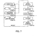
- FIG. 7 is a detailed flowchart of the wafer process in Step 4 in FIG. 6.
- Step 11 oxidation
- Step 12 CVD
- Step 13 electrode formation
- Step 14 ion implantation
- Step 15 resist process
- Step 16 exposure
- Step 17 development
- Step 18 etching
- Step 19 removes disused resist after etching. These steps are repeated, and multilayer circuit patterns are formed on the wafer.
- the device fabrication method of this embodiment may manufacture a higher quality device than the conventional method.
- the device fabrication method using the exposure apparatus 800 and devices as the resultant products would constitute one aspect of the present invention.
- the above differential pumping system 1 or 1A is applicable to a measurement system.
- a reflectometer as one example of this measurement system includes, in addition to the above differential pumping system, a light intensity measuring apparatus for measuring light intensity from a multilayer mirror for EUV light as an object to be measured, an illumination optical system that introduces the light to the multilayer mirror, and a measurement optical system that introduces the light from the multilayer mirror to the light intensity measuring apparatus, therein the light intensity measuring apparatus, illumination optical system and measurement optical system are installed in the above chamber 200.
- the differential pumping system may thus provide high differential pumping performance without harming the use efficiency of the EUV light and maintain performance of an optical element, such as reflectance.
Landscapes
- Epidemiology (AREA)
- Health & Medical Sciences (AREA)
- Public Health (AREA)
- General Physics & Mathematics (AREA)
- Environmental & Geological Engineering (AREA)
- Physics & Mathematics (AREA)
- Engineering & Computer Science (AREA)
- Life Sciences & Earth Sciences (AREA)
- Atmospheric Sciences (AREA)
- Exposure And Positioning Against Photoresist Photosensitive Materials (AREA)
- Exposure Of Semiconductors, Excluding Electron Or Ion Beam Exposure (AREA)
- Structures Of Non-Positive Displacement Pumps (AREA)
- Non-Positive Displacement Air Blowers (AREA)
- Magnetic Bearings And Hydrostatic Bearings (AREA)
- Compressors, Vaccum Pumps And Other Relevant Systems (AREA)
Abstract
Description
Claims (12)
- A differential pumping system comprising:a first chamber for storing a light source that emits light;a second chamber that receives light from the first chamber; anda vacuum pump, provided between said first and second chambers, which includes a hollow shaft through which the light passes, and exhausts the hollow shaft.
- A differential pumping system according to claim 1, wherein a wall surface of the hollow shaft has an aperture, which has a vane section and exhausts gas molecules outside the shaft.
- A differential pumping system according to claim 1, wherein said vacuum pump includes a vane that rotates in the hollow shaft.
- A differential pumping system according to claim 1, further comprising:a first exhaust unit for exhausting said first chamber; anda second exhaust unit for exhausting said second chamber, wherein pressure of the second chamber is lower than that of the first chamber.
- A differential pumping system according to claim 1, wherein the light is collimated and the hollow shaft has a cylindrical shape.
- A differential pumping system according to claim 1, wherein the light is condensed, and the hollow shaft is so tapered that a side of the first chamber is narrower than that of the second chamber.
- A differential pumping system according to claim 1, further comprising another vacuum pump for exhausting an atmosphere to the outside which has been exhausted by the vacuum pump provided between said first and second chambers.
- A differential pumping system according to claim 1, wherein the light is EUV light.
- An exposure apparatus comprising:wherein said illumination optical system and projection optical system are installed in the second chamber.the differential pumping system according to claim 1;an illumination optical system that introduces the light to a mask that forms a circuit pattern to be transferred onto an object; anda projection optical system that introduces the light from the mask onto the object,
- A measurement system comprising:wherein said light intensity measuring apparatus, illumination optical system and measurement optical system are installed in the second chamber.the differential pumping system according to claim 1;a light intensity measuring apparatus for measuring light intensity from an object to be measured;an illumination optical system that introduces the light to the object; anda measurement optical system that introduces the light from the object to said light intensity measuring apparatus,
- A device fabrication method comprising the step of:exposing an object to be exposed, using the exposure apparatus according to claim 9; andperforming a predetermined process for the object exposed.
- Apparatus comprising a first chamber (100) containing a light source (106), a second chamber (200) for receiving light from the light source, and a vacuum pump (300) between the first and second chambers enabling the chambers to be maintained at different pressure from each other,
the vacuum pump (300) having a hollow portion for enabling the light from the light source to pass through it.
Applications Claiming Priority (2)
| Application Number | Priority Date | Filing Date | Title |
|---|---|---|---|
| JP2002261796A JP3703447B2 (en) | 2002-09-06 | 2002-09-06 | Differential exhaust system and exposure apparatus |
| JP2002261796 | 2002-09-06 |
Publications (2)
| Publication Number | Publication Date |
|---|---|
| EP1396760A2 true EP1396760A2 (en) | 2004-03-10 |
| EP1396760A3 EP1396760A3 (en) | 2005-06-29 |
Family
ID=31712344
Family Applications (1)
| Application Number | Title | Priority Date | Filing Date |
|---|---|---|---|
| EP03255468A Withdrawn EP1396760A3 (en) | 2002-09-06 | 2003-09-02 | Differential pumping system and exposure apparatus |
Country Status (3)
| Country | Link |
|---|---|
| US (1) | US6897456B2 (en) |
| EP (1) | EP1396760A3 (en) |
| JP (1) | JP3703447B2 (en) |
Cited By (5)
| Publication number | Priority date | Publication date | Assignee | Title |
|---|---|---|---|---|
| US6891172B2 (en) * | 2002-09-03 | 2005-05-10 | Canon Kabushiki Kaisha | Differential pumping system and exposure apparatus |
| US6897456B2 (en) * | 2002-09-06 | 2005-05-24 | Canon Kabushiki Kaisha | Differential pumping system and exposure apparatus |
| WO2006009169A1 (en) | 2004-07-21 | 2006-01-26 | Nikon Corporation | Exposure method and method for producing device |
| EP1739490A1 (en) * | 2005-06-14 | 2007-01-03 | Philips Intellectual Property GmbH | Radiation energy sensor with extended lifetime |
| EP2181449A4 (en) * | 2007-08-31 | 2012-02-08 | Cymer Inc | System managing gas flow between chambers of an extreme ultraviolet (euv) photolithography apparatus |
Families Citing this family (24)
| Publication number | Priority date | Publication date | Assignee | Title |
|---|---|---|---|---|
| US7394551B2 (en) * | 2003-01-16 | 2008-07-01 | Metrosol, Inc. | Vacuum ultraviolet referencing reflectometer |
| US7126131B2 (en) * | 2003-01-16 | 2006-10-24 | Metrosol, Inc. | Broad band referencing reflectometer |
| US8564780B2 (en) | 2003-01-16 | 2013-10-22 | Jordan Valley Semiconductors Ltd. | Method and system for using reflectometry below deep ultra-violet (DUV) wavelengths for measuring properties of diffracting or scattering structures on substrate work pieces |
| US7164144B2 (en) * | 2004-03-10 | 2007-01-16 | Cymer Inc. | EUV light source |
| JP2005317611A (en) * | 2004-04-27 | 2005-11-10 | Canon Inc | Exposure method and apparatus |
| US7804059B2 (en) | 2004-08-11 | 2010-09-28 | Jordan Valley Semiconductors Ltd. | Method and apparatus for accurate calibration of VUV reflectometer |
| DE102005015274B4 (en) * | 2005-03-31 | 2012-02-23 | Xtreme Technologies Gmbh | Radiation source for generating short-wave radiation |
| US20080129986A1 (en) | 2006-11-30 | 2008-06-05 | Phillip Walsh | Method and apparatus for optically measuring periodic structures using orthogonal azimuthal sample orientations |
| US7696492B2 (en) * | 2006-12-13 | 2010-04-13 | Asml Netherlands B.V. | Radiation system and lithographic apparatus |
| US7663127B2 (en) * | 2007-03-13 | 2010-02-16 | Globalfoundries Inc. | EUV debris mitigation filter and method for fabricating semiconductor dies using same |
| US8115900B2 (en) * | 2007-09-17 | 2012-02-14 | Asml Netherlands B.V. | Lithographic apparatus and device manufacturing method |
| US20090219537A1 (en) * | 2008-02-28 | 2009-09-03 | Phillip Walsh | Method and apparatus for using multiple relative reflectance measurements to determine properties of a sample using vacuum ultra violet wavelengths |
| JP5339742B2 (en) * | 2008-03-04 | 2013-11-13 | ウシオ電機株式会社 | Connection device between a device that emits extreme ultraviolet light and a device that introduces extreme ultraviolet light |
| US8378661B1 (en) * | 2008-05-29 | 2013-02-19 | Alpha-Omega Power Technologies, Ltd.Co. | Solar simulator |
| JP5186347B2 (en) | 2008-12-04 | 2013-04-17 | ギガフォトン株式会社 | Differential exhaust system |
| JP5495547B2 (en) * | 2008-12-25 | 2014-05-21 | キヤノン株式会社 | Processing apparatus and device manufacturing method |
| US8153987B2 (en) | 2009-05-22 | 2012-04-10 | Jordan Valley Semiconductors Ltd. | Automated calibration methodology for VUV metrology system |
| US8867041B2 (en) | 2011-01-18 | 2014-10-21 | Jordan Valley Semiconductor Ltd | Optical vacuum ultra-violet wavelength nanoimprint metrology |
| US8565379B2 (en) | 2011-03-14 | 2013-10-22 | Jordan Valley Semiconductors Ltd. | Combining X-ray and VUV analysis of thin film layers |
| JP5544663B2 (en) * | 2011-05-09 | 2014-07-09 | レーザーテック株式会社 | EUV mask inspection apparatus and EUV mask inspection method |
| US10185234B2 (en) * | 2012-10-04 | 2019-01-22 | Asml Netherlands B.V. | Harsh environment optical element protection |
| US9301381B1 (en) | 2014-09-12 | 2016-03-29 | International Business Machines Corporation | Dual pulse driven extreme ultraviolet (EUV) radiation source utilizing a droplet comprising a metal core with dual concentric shells of buffer gas |
| JP6885851B2 (en) * | 2017-10-27 | 2021-06-16 | エドワーズ株式会社 | Vacuum pumps, rotors, rotor fins, and casings |
| US11662668B2 (en) | 2021-08-30 | 2023-05-30 | Taiwan Semiconductor Manufacturing Co., Ltd. | Lithography contamination control |
Family Cites Families (15)
| Publication number | Priority date | Publication date | Assignee | Title |
|---|---|---|---|---|
| JPH0695159B2 (en) | 1988-12-08 | 1994-11-24 | 富士通株式会社 | Radiation device |
| JPH04164300A (en) * | 1990-10-29 | 1992-06-09 | Fujitsu Ltd | Radiation takeout window and radiation device |
| JP3127511B2 (en) * | 1991-09-19 | 2001-01-29 | 株式会社日立製作所 | Exposure apparatus and method of manufacturing semiconductor device |
| JP2918081B2 (en) * | 1992-09-22 | 1999-07-12 | 株式会社日立製作所 | Developing device and developer cartridge |
| JP2862477B2 (en) | 1993-06-29 | 1999-03-03 | キヤノン株式会社 | Exposure apparatus and method for manufacturing device using the exposure apparatus |
| JP2691865B2 (en) * | 1994-03-18 | 1997-12-17 | 株式会社ソルテック | Extreme UV reduction projection exposure system |
| JPH0862399A (en) * | 1994-08-25 | 1996-03-08 | Nikon Corp | Vacuum device |
| JPH08179514A (en) | 1994-12-22 | 1996-07-12 | Canon Inc | Aligner and exposure method |
| US5963616A (en) * | 1997-03-11 | 1999-10-05 | University Of Central Florida | Configurations, materials and wavelengths for EUV lithium plasma discharge lamps |
| US6576917B1 (en) * | 1997-03-11 | 2003-06-10 | University Of Central Florida | Adjustable bore capillary discharge |
| JP2001272358A (en) * | 2000-03-24 | 2001-10-05 | Nikon Corp | X-ray sample inspection device |
| US6804327B2 (en) * | 2001-04-03 | 2004-10-12 | Lambda Physik Ag | Method and apparatus for generating high output power gas discharge based source of extreme ultraviolet radiation and/or soft x-rays |
| EP1349008A1 (en) | 2002-03-28 | 2003-10-01 | ASML Netherlands B.V. | Lithographic apparatus and device manufacturing method |
| JP4235480B2 (en) * | 2002-09-03 | 2009-03-11 | キヤノン株式会社 | Differential exhaust system and exposure apparatus |
| JP3703447B2 (en) * | 2002-09-06 | 2005-10-05 | キヤノン株式会社 | Differential exhaust system and exposure apparatus |
-
2002
- 2002-09-06 JP JP2002261796A patent/JP3703447B2/en not_active Expired - Fee Related
-
2003
- 2003-09-02 EP EP03255468A patent/EP1396760A3/en not_active Withdrawn
- 2003-09-05 US US10/656,727 patent/US6897456B2/en not_active Expired - Fee Related
Cited By (8)
| Publication number | Priority date | Publication date | Assignee | Title |
|---|---|---|---|---|
| US6891172B2 (en) * | 2002-09-03 | 2005-05-10 | Canon Kabushiki Kaisha | Differential pumping system and exposure apparatus |
| US6897456B2 (en) * | 2002-09-06 | 2005-05-24 | Canon Kabushiki Kaisha | Differential pumping system and exposure apparatus |
| WO2006009169A1 (en) | 2004-07-21 | 2006-01-26 | Nikon Corporation | Exposure method and method for producing device |
| EP1783823A4 (en) * | 2004-07-21 | 2009-07-22 | Nikon Corp | EXPOSURE METHOD AND DEVICE MANUFACTURING METHOD |
| US7914972B2 (en) | 2004-07-21 | 2011-03-29 | Nikon Corporation | Exposure method and device manufacturing method |
| TWI467340B (en) * | 2004-07-21 | 2015-01-01 | 尼康股份有限公司 | An exposure method and an element manufacturing method, and a substrate and a manufacturing method thereof |
| EP1739490A1 (en) * | 2005-06-14 | 2007-01-03 | Philips Intellectual Property GmbH | Radiation energy sensor with extended lifetime |
| EP2181449A4 (en) * | 2007-08-31 | 2012-02-08 | Cymer Inc | System managing gas flow between chambers of an extreme ultraviolet (euv) photolithography apparatus |
Also Published As
| Publication number | Publication date |
|---|---|
| EP1396760A3 (en) | 2005-06-29 |
| US6897456B2 (en) | 2005-05-24 |
| JP2004103731A (en) | 2004-04-02 |
| JP3703447B2 (en) | 2005-10-05 |
| US20040075063A1 (en) | 2004-04-22 |
Similar Documents
| Publication | Publication Date | Title |
|---|---|---|
| US6897456B2 (en) | Differential pumping system and exposure apparatus | |
| JP3626627B2 (en) | Lithographic projection apparatus and device manufacturing method | |
| US6867843B2 (en) | Debris removing system for use in X-ray light source | |
| JP5055310B2 (en) | Lithographic apparatus, radiation system, contaminant trap, device manufacturing method, and method of capturing contaminant in a contaminant trap | |
| US7670754B2 (en) | Exposure apparatus having a processing chamber, a vacuum chamber and first and second load lock chambers | |
| US7091507B2 (en) | Light generator and exposure apparatus | |
| EP1396758B1 (en) | Differential pumping system and exposure apparatus | |
| US7459707B2 (en) | Exposure apparatus, light source apparatus and device fabrication | |
| US7362416B2 (en) | Exposure apparatus, evaluation method and device fabrication method | |
| TWI465857B (en) | Lighting optics, exposure devices and parts manufacturing methods | |
| JP2004519868A (en) | Transparent boundary structure for EUV | |
| JP3919599B2 (en) | Optical element, light source device having the optical element, and exposure apparatus | |
| US7050152B2 (en) | Exposure apparatus | |
| US20050236584A1 (en) | Exposure method and apparatus | |
| US7518132B2 (en) | Light source apparatus, exposure apparatus and device fabrication method | |
| WO2004090957A1 (en) | Light source unit, illumination optical system, exposure apparatus and exposure method | |
| JP2009130366A (en) | Illumination optical apparatus, exposure apparatus, and device manufacturing method | |
| JP5531053B2 (en) | Radiation source, lithographic apparatus and device manufacturing method | |
| US7170579B2 (en) | Light source unit, exposure apparatus, and device manufacturing method | |
| WO2025021415A1 (en) | Optical assembly for an euv projection exposure apparatus, euv projection exposure apparatus | |
| JP2008041391A (en) | Light source apparatus, exposure apparatus, and device manufacturing method | |
| JP2005294608A (en) | Discharge light source unit, illumination optical apparatus, exposure apparatus, and exposure method | |
| JP2007128971A (en) | Differential exhaust system, light source using the same, and exposure apparatus | |
| JP2007027237A (en) | Exposure apparatus, light source apparatus, and device manufacturing method |
Legal Events
| Date | Code | Title | Description |
|---|---|---|---|
| PUAI | Public reference made under article 153(3) epc to a published international application that has entered the european phase |
Free format text: ORIGINAL CODE: 0009012 |
|
| AK | Designated contracting states |
Kind code of ref document: A2 Designated state(s): AT BE BG CH CY CZ DE DK EE ES FI FR GB GR HU IE IT LI LU MC NL PT RO SE SI SK TR |
|
| AX | Request for extension of the european patent |
Extension state: AL LT LV MK |
|
| PUAL | Search report despatched |
Free format text: ORIGINAL CODE: 0009013 |
|
| AK | Designated contracting states |
Kind code of ref document: A3 Designated state(s): AT BE BG CH CY CZ DE DK EE ES FI FR GB GR HU IE IT LI LU MC NL PT RO SE SI SK TR |
|
| AX | Request for extension of the european patent |
Extension state: AL LT LV MK |
|
| 17P | Request for examination filed |
Effective date: 20051229 |
|
| AKX | Designation fees paid |
Designated state(s): DE FR GB NL |
|
| STAA | Information on the status of an ep patent application or granted ep patent |
Free format text: STATUS: THE APPLICATION HAS BEEN WITHDRAWN |
|
| 18W | Application withdrawn |
Effective date: 20120425 |