EP1396746A2 - Zoom lens and camera using the same - Google Patents
Zoom lens and camera using the same Download PDFInfo
- Publication number
- EP1396746A2 EP1396746A2 EP03255359A EP03255359A EP1396746A2 EP 1396746 A2 EP1396746 A2 EP 1396746A2 EP 03255359 A EP03255359 A EP 03255359A EP 03255359 A EP03255359 A EP 03255359A EP 1396746 A2 EP1396746 A2 EP 1396746A2
- Authority
- EP
- European Patent Office
- Prior art keywords
- lens unit
- focus lens
- image plane
- focusing
- zoom lens
- Prior art date
- Legal status (The legal status is an assumption and is not a legal conclusion. Google has not performed a legal analysis and makes no representation as to the accuracy of the status listed.)
- Granted
Links
Images




Classifications
-
- G—PHYSICS
- G02—OPTICS
- G02B—OPTICAL ELEMENTS, SYSTEMS OR APPARATUS
- G02B7/00—Mountings, adjusting means, or light-tight connections, for optical elements
- G02B7/02—Mountings, adjusting means, or light-tight connections, for optical elements for lenses
- G02B7/04—Mountings, adjusting means, or light-tight connections, for optical elements for lenses with mechanism for focusing or varying magnification
- G02B7/10—Mountings, adjusting means, or light-tight connections, for optical elements for lenses with mechanism for focusing or varying magnification by relative axial movement of several lenses, e.g. of varifocal objective lens
- G02B7/102—Mountings, adjusting means, or light-tight connections, for optical elements for lenses with mechanism for focusing or varying magnification by relative axial movement of several lenses, e.g. of varifocal objective lens controlled by a microcomputer
-
- G—PHYSICS
- G02—OPTICS
- G02B—OPTICAL ELEMENTS, SYSTEMS OR APPARATUS
- G02B15/00—Optical objectives with means for varying the magnification
- G02B15/14—Optical objectives with means for varying the magnification by axial movement of one or more lenses or groups of lenses relative to the image plane for continuously varying the equivalent focal length of the objective
- G02B15/16—Optical objectives with means for varying the magnification by axial movement of one or more lenses or groups of lenses relative to the image plane for continuously varying the equivalent focal length of the objective with interdependent non-linearly related movements between one lens or lens group, and another lens or lens group
- G02B15/163—Optical objectives with means for varying the magnification by axial movement of one or more lenses or groups of lenses relative to the image plane for continuously varying the equivalent focal length of the objective with interdependent non-linearly related movements between one lens or lens group, and another lens or lens group having a first movable lens or lens group and a second movable lens or lens group, both in front of a fixed lens or lens group
- G02B15/167—Optical objectives with means for varying the magnification by axial movement of one or more lenses or groups of lenses relative to the image plane for continuously varying the equivalent focal length of the objective with interdependent non-linearly related movements between one lens or lens group, and another lens or lens group having a first movable lens or lens group and a second movable lens or lens group, both in front of a fixed lens or lens group having an additional fixed front lens or group of lenses
- G02B15/17—Optical objectives with means for varying the magnification by axial movement of one or more lenses or groups of lenses relative to the image plane for continuously varying the equivalent focal length of the objective with interdependent non-linearly related movements between one lens or lens group, and another lens or lens group having a first movable lens or lens group and a second movable lens or lens group, both in front of a fixed lens or lens group having an additional fixed front lens or group of lenses arranged +--
Definitions
- the present invention relates to a zoom lens apparatus used in a camera such as TV camera and video camera.
- a rear focus type zoom lens with a focus lens unit (rear focus lens unit) placed closer to the image plane than a variator lens unit has an advantage in reducing size and weight of the focus lens unit, and is therefore widely used for an autofocus type zoom lens.
- a front focus system with a focus lens unit (front focus lens unit) placed closer to an object than a variator lens unit keeps the same amount of movement of the focus lens unit even if magnification is changed and has an advantage for the variator lens unit, and is therefore widely used for a zoom lens apparatus for broadcasting and business which attach importance to manual operations.
- a zoom lens which uses a focus lens unit closer to the image plane side than a variator lens unit for autofocusing and uses a focus lens unit closer to an object than a variator lens unit for manual focusing is disclosed in Japanese Utility Model Publication No. S62(1987)-43286, Japanese Patent Publication No. H5(1993)-6163, Japanese Patent No. 2505835, Japanese Patent No. 2505840 and Japanese Patent No. 2561637.
- broadcast or professional video zoom lenses carry out faster and more accurate focusing operations or intentional focusing operations for image effects compared to consumer ones.
- these focusing operations may not be sufficiently supported by autofocusing alone, and so requires auxiliary manual focusing operations for autofocusing.
- the focus lens unit with the zoom lenses disclosed in the above described publications cannot operate fine focusing because the respective front focus lens units are fixed during autofocusing.
- a rear focus lens unit for fine manual focusing during autofocusing, but it requires an operation mechanism different from the operation mechanism of the front focus lens unit such as an electronic ring, which makes the configuration complicated and produces an uncomfortable feeling during operation to users such as TV camera operators who are used to focusing operations using the front focus lens unit.
- an in-focus range by autofocusing may be restricted by the position of the front focus lens unit, which will prevent the focusing from being achieved in the vicinity of infinity or the minimum object distance.
- One aspect of the present invention comprises a 300m lens apparatus having a variator lens unit which moves in the direction of the optical axis to carry out power variation, an object-side focus lens unit which is placed closer to an object than the variator lens unit and moves in the direction of the optical axis to perform focusing and an image plane-side focus lens unit which is placed closer to the image plane than the variator lens unit and moves in the direction of the optical axis to perform focusing.
- the apparatus further comprises a controller which drives the image plane-side focus lens unit to perform autofocus control when an autofocus mode is set. When the autofocus mode is set, driving of the object-side focus lens unit through manual operations is allowed.
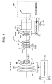
- FIG. 1 is an optical sectional view of a zoom lens apparatus ZA which is an embodiment of the present invention at a wide-angle end.
- the lens unit of the zoom lens apparatus will be explained sequentially starting from components on the object side (left side in FIG. 1).
- reference character F1 denotes a front focus lens unit (object-side focus lens unit) having positive optical power (reciprocal of focal length) as a first lens unit.
- Reference character V denotes a variator lens unit having negative optical power for varying power as a second lens unit, which varies power by monotonously moving on the optical axis toward the image plane from the wide-angle end to the telephoto end.
- Reference character C denotes a compensator lens unit having negative optical power as a third lens unit to compensate for variations in the image plane caused by power variation, which moves on the optical axis describing a nonlinear track which is convex toward an object.
- Reference character SP denotes a diaphragm (stop) and FR denotes a relay lens unit which has positive optical power as a fourth lens unit and is fixed during power variation.
- Reference character F2 denotes a rear focus lens unit (image plane-side focus lens unit) which has positive optical power as a fifth lens unit.
- Reference character P denotes an optical element such as a color separating prism and optical filter, and is illustrated as a glass block in the figure.
- reference numeral 10 denotes a manual focus ring which moves the front focus lens unit F1 in the direction of the optical axis through manual operations.
- Reference numeral 11 denotes a motor which drives the rear focus lens unit F2 in the direction of the optical axis.
- Reference numeral 12 denotes a controller which drives the motor 11 and performs autofocus control using the rear focus lens unit F2 according to a focus command signal from a camera (TV camera or video camera, etc.) CM in which this zoom lens apparatus is mounted or provided as an integral part.
- Reference numeral 13 denotes a mode selection switch which switches between a manual focus mode and autofocus mode. In a manual focus mode, no autofocus control by the controller 12 is carried out and in an autofocus mode, autofocus control by the controller 12 is carried out and manual operations of the front focus lens unit F1, which will be described later, can also be carried out.
- Reference character IP in the camera CM denotes an image pickup element which receives the image of an object formed by the zoom lens apparatus ZA and photoelectrically converts this.
- the output signal from the image pickup element IP is subjected to various types of processing by an image processing circuit (not shown) provided inside the camera CM and recorded in a recording medium (not shown) such as a magnetic tape, semiconductor memory and optical disk.
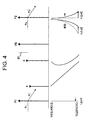
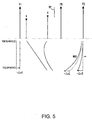
- FIGS. 2 to 5 show schematic views of the optical system of this zoom lens apparatus ZA.
- Up-arrows in the upper half in each figure indicate that the lens unit has positive optical power and down-arrows in the lower half indicate that the lens unit has negative optical power.
- straight lines or curves in the lower half in each figure indicate moving tracks between the wide angle end and telephoto end of the movable lens unit.
- Reference character MOD denotes the minimum object distance and ⁇ denotes infinity.
- FIG. 2 shows a case where the rear focus lens unit F2 is fixed and focusing is performed only using the front focus lens unit F1 between the minimum object distance and infinity. In this case, the movement amount of the front focus lens unit F1 doe not change with the zooming state (focal length of the entire system).
- FIG. 3 shows a case where focusing is performed using the rear focus lens unit F2 between the minimum object distance and infinity.
- the movement amount of the rear focus lens unit F2 changes with the zooming state and increases as the zooming state comes closer to the telephoto side.
- FIG. 4 shows the front focus lens unit F1 which has been moved from the position where focusing to infinity is achieved (hereinafter referred to as the infinity focusing position) toward the object by ⁇ x1 (- ⁇ x1) for fine adjustment of focusing in an autofocus mode in which autofocusing is carried out by the controller 12 driving the rear focus lens unit F2.
- the moving track of the rear focus lens unit F2 between infinity and the minimum object distance is deviated from the moving track shown in FIG. 3 toward the image plane and the amount of deviation ⁇ x2 (+ ⁇ x2) becomes a maximum at the telephoto end.
- FIG. 5 shows the front focus lens unit F1 which has been moved from the infinity focusing position toward the image plane by ⁇ x1 (+ ⁇ x1).
- the moving track of the rear focus lens unit F2 is deviated toward the object which is the direction opposite that in the case of FIG. 4 and the amount of deviation ⁇ x2 (- ⁇ x2) reaches a maximum at the telephoto end.
- the zoom lens apparatus of this embodiment preferably satisfies the following conditional expression (6): 1 ⁇
- This conditional expression (6) is a condition for preventing the focusing range of autofocus by the rear focus lens unit F2 from the infinity to the minimum object distance from being limited when the front focus lens unit F1 is moved as a result of fine adjustment of focusing and specifies the relationship between the movement amount ⁇ x1 of the front focus lens unit F1 and amount of movement margin ⁇ x2 of the rear focus lens unit F2.
- the zoom lens apparatus of this embodiment preferably satisfies the following conditional expression (7):
- Sx1 denotes the movement amount of the front focus lens unit F1 from the position where focusing to the minimum object distance is achieved (hereinafter referred to as the minimum object distance focusing position) toward the object with respect to the infinity focusing position.
- conditional expression (7) By specifying the upper limit of ⁇ x1 as shown in conditional expression (7), it is possible to suppress upsizing of the zoom lens apparatus due to an increase in the movement amount of the front focus lens unit F1. That is, when the value of the above described ratio exceeds the upper limit of conditional expression (7), the movement amount of the front focus lens unit F1 increases, which will increase the diameter of the front focus lens unit F1 and the total length of the zoom lens considerably.
- the movement amount ⁇ x2 of the rear focus lens unit F2 to compensate for defocusing generated by the movement of the front focus lens unit F1 increases considerably, resulting in an increase in the space required before and after the rear focus lens unit F2, an increase in size of the zoom lens or an increase in aberration variations with the increase in the movement amount of the rear focus lens unit F2, which is not preferable.
- the movable stopper S may be specifically constructed, for example, of a stopper S, a mechanism (not shown) which causes this stopper S to stick out within the operation range of the manual focus ring 10 in the autofocus mode and exit from the operation area in the manual focus mode and a mechanism (not shown) which moves the stopper S to a position in the operation area of the manual focus ring 10 in which it is possible to obtain ⁇ x1 that satisfies conditional expressions (6) and (7).
- any configuration can be used if it is at least functionally equivalent.
- Table 1 shows a numerical example of the zoom lens apparatus of the above described embodiment.
- reference character f denotes the focal length of the entire system
- ri, di, ni and ⁇ i denote the radius of curvature, distance between optical surfaces, refractive index and Abbe's number of the m-th optical surface from the object side, respectively.
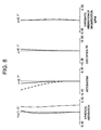
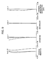
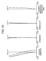
- FIGS. 6 to 10 illustrate aberration of this numerical example.
- the front focus lens unit F1 as the first lens unit in this numerical example has positive optical power and moves to the object side on the optical axis when focusing on an object at a short distance.
- the movement amount Sx1 of the front focus lens unit F1 at the minimum object distance of 1.0 m is -6.3173 mm in the entire area of zooming when the image plane side is assumed to be positive.
- the front focus lens unit F1 has an air distance of 2.77 mm from the variator lens unit V when focusing is achieved at infinity and secures 2.0 mm as the range of movement ⁇ x1 in the autofocus mode.
- the rear focus lens unit F2 as the fifth lens unit in this numerical example has positive optical power and moves toward the object side on the optical axis when focusing on an object at a short distance.
- the movement amount of the rear focus lens unit F2 at the minimum object distance of 1.0 m is -0.065 mm at the wide angle end and -8.239 mm at the telephoto end, where the image plane side is assumed to be positive.
- the air interval between the relay lens unit FR which is the fourth lens unit and rear focus lens unit F2 is 22.0 mm
- the back focal distance is 37.2 mm (equivalent in the air)
- 4.5 mm is secured as the amount of movement margin ⁇ x2 of the rear focus lens unit F2.
- conditional expression (7) is:
- 1.03 which satisfies the condition.
- a movable stopper S which operates only in the autofocus mode is provided so that the movement amount of the front focus lens unit F1 does not exceed ⁇ 2.0 mm.
- the above described embodiment has described the zoom lens apparatus based on a zooming system with the second lens unit and third lens unit in a configuration of positive, negative, negative and positive lenses moving during power variation, but the present invention is not limited to the zoom system and is also applicable to a zoom lens having focus lens units closer to the object and image plane than the variator lens unit.
- a zoom lens apparatus for broadcast or professional video often uses a zoom system with the second lens unit moving for power variation and the third lens unit moving for compensation for variations of the image plane in a configuration of positive, negative, positive and positive lenses, but it is also possible to use the first lens unit as the object-side focus lens unit and the fourth lens unit as the image plane-side focus lens unit. Furthermore, there can also be three or more lens units which move during power variation.
- the above described embodiment performs focusing by movement of the entire first lens unit, but the present invention can adapt to a zoom lens apparatus in which only some lens elements of the first lens unit are used for focusing.
- the above described embodiment has described the case where the lens unit closest to the image plane is used as the image plane-side focus lens unit, but any lens unit can be used as the image plane-side focus lens unit if it is at least closer to the image plane than the variator lens unit.
- this embodiment can realize a small zoom lens apparatus capable of realizing faster and more accurate focusing through manual operations, easily performing intentional focusing for image effects and allowing focusing through manual operations in the autofocus mode without losing operational feeling of manual focusing.
Landscapes
- Physics & Mathematics (AREA)
- General Physics & Mathematics (AREA)
- Optics & Photonics (AREA)
- Nonlinear Science (AREA)
- Engineering & Computer Science (AREA)
- General Engineering & Computer Science (AREA)
- Lenses (AREA)
- Lens Barrels (AREA)
- Studio Devices (AREA)
Abstract
Description
| f=8.13945(mm) | fno 1:1.52∼1.77 | 2ω=52.3° - 4.1° | |||||
| r1= | 1169.481 | d1= | 2.40 | n1= | 1.81265 | ν1= | 25.4 |
| r2= | 98.429 | d2= | 10.83 | n2= | 1.51825 | ν2= | 64.2 |
| r3= | -265.170 | d3= | 0.20 | 1.00000 | |||
| r4= | 124.037 | d4= | 8.29 | n3= | 1.60548 | ν3= | 60.7 |
| r5= | -281.395 | d5= | 0.20 | 1.00000 | |||
| r6= | 51.797 | d6= | 6.46 | n4= | 1.64254 | ν4= | 60.1 |
| r7= | 97.915 | d7= | variable | 1.00000 | |||
| r8= | 71.045 | d8= | 0.90 | n5= | 1.82017 | ν5= | 46.6 |
| r9= | 17.601 | d9= | 6.01 | 1.00000 | |||
| r10= | -21.542 | d10= | 0.90 | n6= | 1.77621 | ν6= | 49.6 |
| r11= | 18.397 | d11= | 4.63 | n7= | 1.85501 | ν7= | 23.9 |
| r12= | -4295.134 | d12= | variable | 1.00000 | |||
| r13= | -27.245 | d13= | 0.90 | n8= | 1.79013 | ν8= | 44.2 |
| r14= | 31.613 | d14= | 3.84 | n9= | 1.85501 | ν9= | 23.9 |
| r15= | 1125.345 | d15= | variable | 1.00000 | |||
| r16= | (diaphragm) | d16= | 1.60 | 1.00000 | |||
| r17= | d17= | 4.73 | n10= | 1.62287 | ν10= | 60.3 | |
| r18= | -30.301 | d18= | 0.20 | 1.00000 | |||
| r19= | -314.637 | d19= | 6.99 | n11= | 1.52033 | ν11= | 58.9 |
| r20= | -19.154 | d20= | 1.20 | n12= | 1.83945 | ν12= | 42.7 |
| r21= | -62.330 | d21= | 0.20 | 1.00000 | |||
| r22= | 47.509 | d22= | 5.72 | n13= | 1.51977 | ν13= | 52.4 |
| r23= | -83.974 | d23= | variable | 1.00000 | |||
| r24= | 95.840 | d24= | 1.20 | n14= | 1.85504 | ν14= | 23.8 |
| r25= | 32.514 | d25= | 2.01 | 1.00000 | |||
| r26= | 78.907 | d26= | 4.80 | n15= | 1.48915 | ν15= | 70.2 |
| r27= | -46.367 | d27= | 0.20 | 1.00000 | |||
| r28= | 28.293 | d28= | 5.65 | n16= | 1.48915 | ν16= | 70.2 |
| r29= | -133.006 | d29= | variable | 1.00000 | |||
| r30= | d30= | 29.00 | n17= | 1.60718 | ν17= | 38.0 | |
| r31= | d31= | 11.20 | n18= | 1.51825 | ν18= | 64.2 | |
| r32= | d32= | 8.00 | 1.00000 |
| Focal length/ Variable interval |
8.14 | 30.12 | 111.51 |
| d7 | 2.78 | 30.48 | 49.55 |
| d12 | 50.26 | 14.17 | 3.78 |
| d15 | 1.81 | 6.20 | 1.52 |
| d23 | 22.00 | 22.00 | 22.00 |
| d29 | 7.80 | 7.80 | 7.80 |
Claims (8)
- A zoom lens apparatus which comprises a variator lens unit which carries out power variation by moving in the direction of the optical axis; an object-side focus lens unit provided closer to the object than the variator lens unit for carrying out focusing by moving in the direction of the optical axis; an image plane-side focus lens unit provided closer to an image plane than the variator lens unit for carrying out focusing by moving in the direction of the optical axis; and a controller which controls autofocus by driving the image plane-side focus lens unit when an autofocus mode is set, characterized in that,
driving of the object-side focus lens unit through manual operations is allowed when the autofocus mode is set. - The zoom lens apparatus according to claim 1, characterized by comprising a limiting member which limits the movement range of the object-side focus lens unit in the autofocus mode.
- The zoom lens apparatus according to claim 1 or 2, characterized in that the following condition is satisfied:
- The zoom lens apparatus according to any one of claims 1 to 3, characterized in that the following condition is satisfied:
- The zoom lens apparatus according to claim 3, characterized by comprising a movable limiting member which limits the movement range of the object-side focus lens unit in the autofocus mode so as not to exceed the allowable movement amount Δx1 specified by the conditional expression according to claim 3.
- The zoom lens apparatus according to claim 4, characterized by comprising a movable limiting member which limits the movement range of the object-side focus lens unit in the autofocus mode so as not to exceed the allowable movement amount Δx1 specified by the conditional expression according to claim 4.
- The zoom lens apparatus according to any one of claims 1 to 6, characterized by comprising:a first lens unit which has positive optical power as the object-side focus lens unit which is fixed during power variation;a second lens unit which has negative optical power as the variator lens unit;a third lens unit which compensates for image plane variations caused by power variation by moving in the direction of the optical axis;a fixed fourth lens unit; anda positive fifth lens unit as the image plane-side focus lens unit, in that order from the object side.
- A camera system characterized by comprising:a zoom lens apparatus according to any one of claims 1 to 7; anda camera in which the zoom lens apparatus is mounted for recording an object image formed by the zoom lens apparatus.
Applications Claiming Priority (2)
| Application Number | Priority Date | Filing Date | Title |
|---|---|---|---|
| JP2002255355A JP4298241B2 (en) | 2002-08-30 | 2002-08-30 | Zoom lens device |
| JP2002255355 | 2002-08-30 |
Publications (3)
| Publication Number | Publication Date |
|---|---|
| EP1396746A2 true EP1396746A2 (en) | 2004-03-10 |
| EP1396746A3 EP1396746A3 (en) | 2004-03-17 |
| EP1396746B1 EP1396746B1 (en) | 2005-11-16 |
Family
ID=31712268
Family Applications (1)
| Application Number | Title | Priority Date | Filing Date |
|---|---|---|---|
| EP03255359A Expired - Lifetime EP1396746B1 (en) | 2002-08-30 | 2003-08-28 | Zoom lens and camera using the same |
Country Status (4)
| Country | Link |
|---|---|
| US (1) | US6847495B2 (en) |
| EP (1) | EP1396746B1 (en) |
| JP (1) | JP4298241B2 (en) |
| DE (1) | DE60302305T2 (en) |
Cited By (2)
| Publication number | Priority date | Publication date | Assignee | Title |
|---|---|---|---|---|
| EP1591819A1 (en) * | 2004-04-28 | 2005-11-02 | Canon Kabushiki Kaisha | Drive controller of a lens system |
| JP2012185272A (en) * | 2011-03-04 | 2012-09-27 | Canon Inc | Zoom lens and imaging apparatus having the same |
Families Citing this family (3)
| Publication number | Priority date | Publication date | Assignee | Title |
|---|---|---|---|---|
| JP4708737B2 (en) * | 2004-06-04 | 2011-06-22 | キヤノン株式会社 | Lens device |
| CN104267486B (en) * | 2014-10-14 | 2016-06-15 | 福建福光股份有限公司 | 25.2 zoom high definition television pick-up lens again |
| JP6377009B2 (en) * | 2015-04-24 | 2018-08-22 | キヤノン株式会社 | Optical system and imaging apparatus having the same |
Family Cites Families (4)
| Publication number | Priority date | Publication date | Assignee | Title |
|---|---|---|---|---|
| JPS58129404A (en) * | 1982-01-27 | 1983-08-02 | Minolta Camera Co Ltd | Zoom lens system capable of manual and automatic focusing |
| JPS59214814A (en) * | 1983-05-20 | 1984-12-04 | Canon Inc | zoom lens device |
| US4890132A (en) * | 1987-03-26 | 1989-12-26 | Asahi Kogaku Kogyo Kabushiki Kaisha | Manual control apparatus of zoom lens barrel for an auto focus camera |
| US5448328A (en) * | 1992-02-07 | 1995-09-05 | Canon Kabushiki Kaisha | Vibration driven system |
-
2002
- 2002-08-30 JP JP2002255355A patent/JP4298241B2/en not_active Expired - Fee Related
-
2003
- 2003-08-28 DE DE60302305T patent/DE60302305T2/en not_active Expired - Lifetime
- 2003-08-28 EP EP03255359A patent/EP1396746B1/en not_active Expired - Lifetime
- 2003-08-29 US US10/651,795 patent/US6847495B2/en not_active Expired - Fee Related
Cited By (3)
| Publication number | Priority date | Publication date | Assignee | Title |
|---|---|---|---|---|
| EP1591819A1 (en) * | 2004-04-28 | 2005-11-02 | Canon Kabushiki Kaisha | Drive controller of a lens system |
| US7254322B2 (en) | 2004-04-28 | 2007-08-07 | Canon Kabushiki Kaisha | Drive controller of a lens apparatus |
| JP2012185272A (en) * | 2011-03-04 | 2012-09-27 | Canon Inc | Zoom lens and imaging apparatus having the same |
Also Published As
| Publication number | Publication date |
|---|---|
| US6847495B2 (en) | 2005-01-25 |
| JP2004093938A (en) | 2004-03-25 |
| JP4298241B2 (en) | 2009-07-15 |
| US20040051966A1 (en) | 2004-03-18 |
| DE60302305T2 (en) | 2006-06-29 |
| EP1396746B1 (en) | 2005-11-16 |
| DE60302305D1 (en) | 2005-12-22 |
| EP1396746A3 (en) | 2004-03-17 |
Similar Documents
| Publication | Publication Date | Title |
|---|---|---|
| US5757554A (en) | Zoom lens | |
| JP5046740B2 (en) | Zoom lens and imaging apparatus having the same | |
| US5585969A (en) | Zoom lens | |
| US4934796A (en) | Zoom lens | |
| JP2988164B2 (en) | Rear focus zoom lens | |
| US5059007A (en) | Internally focusing zoom lens | |
| US6002528A (en) | Zoom lens | |
| JPH02201310A (en) | Zoom lens with internal focus lens | |
| JP2001166208A (en) | Zoom lens | |
| US5528427A (en) | Zoom lens | |
| US20090040625A1 (en) | Zoom lens system and image pickup apparatus including the same | |
| JPH06242378A (en) | Zoom lens | |
| JP2006058584A (en) | Zoom lens and imaging apparatus having the same | |
| US7227699B2 (en) | Zoom lens system and image pick-up apparatus including same | |
| US5204779A (en) | Zoom lens capable of being adjusted for tracking | |
| JP4717399B2 (en) | Zoom lens and imaging apparatus having the same | |
| JP3123747B2 (en) | Zoom lens | |
| JP3363688B2 (en) | Zoom lens | |
| JPH0882743A (en) | Rear focus type zoom lens | |
| US5191475A (en) | Zoom lens | |
| JP2006047771A (en) | Zoom lens and image pickup apparatus using the same | |
| EP1396746B1 (en) | Zoom lens and camera using the same | |
| JPH0713079A (en) | Rear focus type telephoto zoom lens | |
| US4712883A (en) | Rear focus zoom lens | |
| JP3144059B2 (en) | Rear focus zoom lens |
Legal Events
| Date | Code | Title | Description |
|---|---|---|---|
| PUAI | Public reference made under article 153(3) epc to a published international application that has entered the european phase |
Free format text: ORIGINAL CODE: 0009012 |
|
| PUAL | Search report despatched |
Free format text: ORIGINAL CODE: 0009013 |
|
| AK | Designated contracting states |
Kind code of ref document: A2 Designated state(s): AT BE BG CH CY CZ DE DK EE ES FI FR GB GR HU IE IT LI LU MC NL PT RO SE SI SK TR |
|
| AX | Request for extension of the european patent |
Extension state: AL LT LV MK |
|
| AK | Designated contracting states |
Kind code of ref document: A3 Designated state(s): AT BE BG CH CY CZ DE DK EE ES FI FR GB GR HU IE IT LI LU MC NL PT RO SE SI SK TR |
|
| AX | Request for extension of the european patent |
Extension state: AL LT LV MK |
|
| RIN1 | Information on inventor provided before grant (corrected) |
Inventor name: RYUJI, NURISHIC/O CANON KABUSHIKI KAISHA |
|
| 17P | Request for examination filed |
Effective date: 20040729 |
|
| 17Q | First examination report despatched |
Effective date: 20040827 |
|
| AKX | Designation fees paid |
Designated state(s): DE FR GB |
|
| GRAP | Despatch of communication of intention to grant a patent |
Free format text: ORIGINAL CODE: EPIDOSNIGR1 |
|
| GRAS | Grant fee paid |
Free format text: ORIGINAL CODE: EPIDOSNIGR3 |
|
| GRAA | (expected) grant |
Free format text: ORIGINAL CODE: 0009210 |
|
| AK | Designated contracting states |
Kind code of ref document: B1 Designated state(s): DE FR GB |
|
| REG | Reference to a national code |
Ref country code: GB Ref legal event code: FG4D |
|
| REF | Corresponds to: |
Ref document number: 60302305 Country of ref document: DE Date of ref document: 20051222 Kind code of ref document: P |
|
| ET | Fr: translation filed | ||
| PLBE | No opposition filed within time limit |
Free format text: ORIGINAL CODE: 0009261 |
|
| STAA | Information on the status of an ep patent application or granted ep patent |
Free format text: STATUS: NO OPPOSITION FILED WITHIN TIME LIMIT |
|
| 26N | No opposition filed |
Effective date: 20060817 |
|
| REG | Reference to a national code |
Ref country code: FR Ref legal event code: PLFP Year of fee payment: 13 |
|
| PGFP | Annual fee paid to national office [announced via postgrant information from national office to epo] |
Ref country code: GB Payment date: 20150826 Year of fee payment: 13 Ref country code: DE Payment date: 20150831 Year of fee payment: 13 |
|
| PGFP | Annual fee paid to national office [announced via postgrant information from national office to epo] |
Ref country code: FR Payment date: 20150826 Year of fee payment: 13 |
|
| REG | Reference to a national code |
Ref country code: DE Ref legal event code: R119 Ref document number: 60302305 Country of ref document: DE |
|
| GBPC | Gb: european patent ceased through non-payment of renewal fee |
Effective date: 20160828 |
|
| REG | Reference to a national code |
Ref country code: FR Ref legal event code: ST Effective date: 20170428 |
|
| PG25 | Lapsed in a contracting state [announced via postgrant information from national office to epo] |
Ref country code: DE Free format text: LAPSE BECAUSE OF NON-PAYMENT OF DUE FEES Effective date: 20170301 Ref country code: FR Free format text: LAPSE BECAUSE OF NON-PAYMENT OF DUE FEES Effective date: 20160831 Ref country code: GB Free format text: LAPSE BECAUSE OF NON-PAYMENT OF DUE FEES Effective date: 20160828 |