Technical Field
The present invention relates to an ultrasonic flow measuring device, and particularly to an
ultrasonic flow measuring device having a pair of ultrasonic transducers disposed on the outer
peripheral surface on the upstream and downstream sides of a conduit pipe in which fluid flows in a
fixed direction, wherein a regular orientation and position are applied to the ultrasonic transducers
so that a propagation plane formed of a propagation path of an ultrasonic wave on which an
ultrasonic wave transmitted from one ultrasonic transducer is reflected by the inner peripheral
surface of the conduit pipe and received by the other ultrasonic transducer contains the axis line of
the conduit pipe, thereby measuring the velocity of the fluid flowing in the conduit pipe.
Background Technique
The principle of this type of ultrasonic flow measuring device will be described with reference to Fig.
15. In an ultrasonic flow measuring device 200 of Fig. 15, fluid to be measured flows in a direction
indicated by an arrow FD in a conduit pipe 60. A pair of ultrasonic transducers each comprising a
vibrator 71 and a plastic wedge 72 are disposed on the outer peripheral surface of the conduit pipe
60 so as to be spaced from each other by a predetermined distance. An acoustic coupling medium
79 for acoustic matching is coated between each wedge 72 and the outer peripheral surface of the
conduit pipe 60 to enhance the propagation efficiency of ultrasonic waves. As indicated by a thin line
having arrows, a wave transmitted from one ultrasonic transducer is reflected by the inner peripheral
surface of the conduit pipe 60, and then received by the other ultrasonic transducer. A plane
containing a propagation path of this ultrasonic wave is referred to as a propagation plane.
Describing in connection with Fig. 15, the propagation plane corresponds to the sheet face
containing the axis line of the conduit pipe 60.
When the ultrasonic transducers 70 are regularly oriented and positioned so that ultrasonic waves
travel on the propagation plane, representing the velocity of the fluid flowing in the conduit pipe 60
by V, representing the propagation path length by L and representing the acoustic velocity by c, the
time difference Δt between the forward and backward directions with respect to the flowing direction
concerning the arrival time from one ultrasonic transducer to the other ultrasonic transducer
(propagation time difference) is represented by the following equation (1). That is,
Δt = 2LV/c2
As is apparent from this equation (1), when the propagation time difference Δt is obtained from a
measurement, the flow velocity can be derived. Furthermore, when the cross-sectional area of the
conduit pipe 60 is known, the flow rate of the fluid flowing through the conduit pipe can be estimated
by using the flow velocity thus obtained.
Fig. 16 is a plan view showing an example of a conventional ultrasonic flow measuring device
constructed on the basis of the above-described principle, Fig. 17 is an enlarged plan view showing
the surrounding of a ultrasonic transducer of Fig. 16, and Fig. 18 is an enlarged front view showing
further details of the surrounding of the ultrasonic transducer of Fig. 16. In the ultrasonic flow
measuring device 201 of Fig. 16, a pair of ultrasonic transducers 70 are straightly guided in parallel
to the axial line of the conduit pipe 60 by a guide rail 80. The guide rail 80 comprises two frames, is
disposed in parallel to the axial line of the conduit pipe 60 and guides the ultrasonic transducers 70
by pinching the side surfaces of the inserted ultrasonic transducers 70 from both sides. Both ends of
the guide rail 80 are joined to saddles 81. These saddles 81 are secured to the outer peripheral
surface of the conduit pipe 60 by belts 82 formed of metal or plastic.
The ultrasonic transducers 70 are guided along the guide rail so as to be straightly movable. The
positioning of the ultrasonic transducers 70 is carried out so that transmission/reception of ultrasonic
waves is carried out along a thin line RT with arrows of Fig. 15. As shown in Fig. 18, a positioning
shaft 78 is implanted on the wedge 72 of each ultrasonic transducer 70 vertically to the bottom
surface. In this case, a screw member (not shown) which is coaxial with the positioning shaft 78 and
cylindrical in shape and has screw threads formed on the inner and outer sides thereof is disposed.
The screw thread at the outer side of the screw member is engaged with the screw thread formed at
the inner side of a position fixing screw 75, and the screw thread at the inner side of the screw
member is engaged with the screw thread formed at the outer side of a height adjusting screw 76.
When the position fixing screw 75 is rotated, the guide rail 80 is pinched by the upper surface of a
plate member (not shown) joined to the bottom portion of the screw member and the lower surface of
the position fixing screw 75, whereby the guide rail 80 can be fixed so that the transceivers 70
cannot be moved in the axial direction of the conduit pipe 60. Furthermore, when the height
adjusting screw 76 is rotated, the ultrasonic transducers 70 are upwardly and downwardly moved
with respect to the screw member. Accordingly, in the fixing step, the distance between the
ultrasonic transducers 70 is adjusted on the basis of graduations on scales secured to the guide rail
80 so that a cursor 85 secured to each ultrasonic transducer 70 is positioned at an indicated
dimension, the ultrasonic transducer 70 is fixed at the position by the position fixing screw 75 and
each ultrasonic transducer 70 is brought into close contact with the upper surface of the conduit pipe
60 by the height adjusting screw 76.
In the above-described conventional example, in order to enable the ultrasonic transducers to
precisely perform the transmission and reception of ultrasonic waves along the thin line RT with the
arrows mutually, it is necessary to secure the ultrasonic transducers so that the propagation plane of
the ultrasonic waves contains the axial line of the conduit pipe and the mutual distance between the
ultrasonic transducers is appropriate. In this case, according to the graduations of the scales
secured to the guide rail, the cursors secured to the ultrasonic transducers are positioned at the
indicated dimensions to adjust the interval therebetween, and the ultrasonic transducers are fixed at
the proper positions of the guide rail so as to be brought into close contact with the upper surface of
the guide pipe by the fixing screws and the height adjusting screws. Therefore, it is not easy to
secure the ultrasonic transducers with high precision. Accordingly, it takes much time to carry out
the working, and a worker is required to have skill. Furthermore, since the ultrasonic transducers are
coated with the acoustic coupling medium and then they are set up while positioning the guide rail to
the outer peripheral surface of the guide pipe by using belts, there occur such problems that the
fixing screw may slacken, a displacement may occur in the mutual interval between the ultrasonic
transducers, the acoustic coupling medium may be exfoliated or hardened, the ultrasonic
transducers may not be brought into close contact with the conduit pipe and an adverse effect may
occur in the characteristic.
The present invention has been implemented to solve the above problems, and its object is to
provide an ultrasonic flow measuring device that allows accurate setting of the orientation and
position of ultrasonic transducers without difficulty, and enhance workability such as shortage of a
working time.
SUMMARY OF THE INVENTION
In order to solve the above problems, according to the invention of claim 1, an ultrasonic flow
measuring device including a pair of ultrasonic transducers disposed on the outer peripheral surface
on the upstream and downstream sides of a conduit pipe through which fluid flows in a fixed
direction is disposed, regular orientation and position are applied to the ultrasonic transducers so
that a propagation plane constituted by a propagation path of ultrasonic waves contains an axial line
of the conduit pipe then an ultrasonic wave transmitted from one ultrasonic transducer is reflected by
the inner peripheral surface of the conduit pipe and received by the other ultrasonic transducer,
thereby measuring the velocity of the fluid flowing in the conduit pipe, is equipped with a positioning
mechanism for positioning the ultrasonic transducers every desired interval to apply the regular
orientation and position to the ultrasonic transducers.
According the construction described above, the positioning mechanism can determine the positions
of the ultrasonic transducers every desired interval, and if the optimum positioning is selected, the
regular orientation and position can be automatically applied to the ultrasonic transducers.
In the invention of claim 1, the positioning mechanism has a guide frame that is mounted on the
surface of the conduit pipe and guides the ultrasonic transducers straightly in the axial direction of
the conduit pipe, a positioning frame that is fixed to the guide frame and holds an outer edge having
a saw-tooth shape in parallel to the axial line, and positioning means that is fixed to each ultrasonic
transducer and contains a positioning spring, the ultrasonic transducer being positioned by engaging
a tip of the positioning spring with a proper saw-tooth portion of the positioning frame to thereby
apply the regular orientation and position to the ultrasonic transducer. In this case, since the saw-tooth
portion has a recess portion and a projecting portion every fixed interval, for example if the tip
of the positioning spring is fitted in the recess portion, the ultrasonic transducer can be positioned
every fixed interval (the invention of claim 2).
In the invention of claim 1, the positioning mechanism has a guide frame that is mounted on the
surface of the conduit pipe and guides the ultrasonic transducers straightly in the axial direction of
the conduit pipe, a positioning portion that is integrated with the guide frame and holds positioning
holes formed at a fixed interval in parallel to the axial line, and positioning means for fixing each
ultrasonic transducer mounted on the guide frame at a desired position by using the positioning hole
and applying the regular orientation and position to the ultrasonic transducer. In this case, the
ultrasonic transducer can be positioned by a member having a simple shape (the invention of claim
3).
In the invention of claim 1, the positioning mechanism has a guide frame that is mounted on the
surface of the conduit pipe, can guide the ultrasonic transducers straightly in the axial direction of
the conduit pipe, and has plural positioning holes formed on the side surface, and positioning means
that is fixed to each ultrasonic transducer and has a positioning projection formed thereon, when the
ultrasonic transducer is mounted on the guide frame, the positioning projection being fitted into a
desired position hole to apply the regular orientation and position to the ultrasonic transducer.
Accordingly, if the ultrasonic transducer with which the positioning means is sub-assembled is
inserted into the guide frame mounted on the conduit pipe, the ultrasonic transducer can be mounted
on the guide frame through one-touch operation (the invention of claim 4).
In the invention of any one of claims 2 to 4, the positioning means contains a spring member for
pressing each ultrasonic transducer onto the conduit pipe with elastic force when the ultrasonic
transducers are mounted on the guide frame. In this case, it is unnecessary that the ultrasonic
transducer is adjusted to come into contact with the conduit pipe (the invention of claim 5).
In the invention of any one of claims 1 to 5, the guide frame can be secured to the outer peripheral
surface of the conduit pipe as another step before the installation of the ultrasonic transducers is
completed. Accordingly, after the installation of the guide frame is completed, the installation of the
ultrasonic transducers can be performed separately. Therefore, the guide frame can be installed with
no effect of the position of the acoustic coupling medium, so that the working time can be shortened
(the invention of claim 6).
BRIEF DESCRIPTION OF THE DRAWINGS
- Fig. 1
- is a front view showing an embodiment 1 of an ultrasonic flow measuring device
according to the present invention.
- Fig. 2
- is a plan view of the ultrasonic flow measuring device of Fig. 1 which is viewed from the
lower side.
- Fig. 3
- is an enlarged view showing the details of the surrounding of a positioning shaft of
ultrasonic transducers shown in Fig. 1 and Fig. 2.
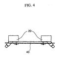
- Fig. 4
- is a diagram showing the fabrication of the ultrasonic transducers and the positioning
frame of the ultrasonic flow measuring device of Fig. 1.
- Fig. 5
- is a diagram showing the fabrication of the guide frame and the conduit pipe of the
ultrasonic flow measuring device of Fig. 1.
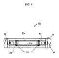
- Fig. 6
- is a plan view showing an embodiment 2 of the ultrasonic flow measuring device
according to the present invention.
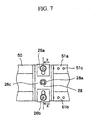
- Fig. 7
- is an enlarged view showing the details of the surrounding of a positioning shaft of
ultrasonic transducers shown in Fig. 6.
- Fig. 8
- is a cross-sectional view taken along a line X-X of Fig. 7.
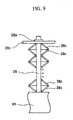
- Fig. 9
- is a diagram showing a case where a disc spring is used in place of a coil spring of Fig. 8.
- Fig. 10
- is a front view showing an embodiment 3 of the ultrasonic flow measuring device
according to the present invention.
- Fig. 11
- is a plan view of the ultrasonic flow measuring device of Fig. 10 which is viewed from the
lower side.
- Fig. 12
- is an enlarged view showing the details of the surrounding of the positioning shaft of the
ultrasonic transducers shown in Fig. 10.
- Fig. 13
- is a cross-sectional view taken along a line Y-Y of Fig. 12.
- Fig. 14
- is a diagram showing a sub assembly state of the ultrasonic transducers before the
ultrasonic transducers are installed as shown in Fig. 10.
- Fig. 15
- is a diagram showing the principle of the ultrasonic flow measuring device.
- Fig. 16
- is a plan view showing a conventional example of the ultrasonic flow measuring device.
- Fig. 17
- is an enlarged view showing the details of the surrounding of the ultrasonic transducers of
Fig. 16.
- Fig. 18
- is a front view showing the details of the structure shown in Fig. 17.
BEST MODES FOR CARRYING OUT THE INVENTION
An embodiment 1 according to the present invention will be described with reference to the
accompanying drawings.
Fig. 1 is a front view showing an embodiment 1 of an ultrasonic flow measuring device according to
the present invention, Fig. 2 is a plan view of the ultrasonic flow measuring device of Fig. 1 which is
viewed from the lower side, Fig. 3 is an enlarged view showing the details of the surrounding of the
positioning shaft of the ultrasonic transducer shown in Figs. 1 and 2, Fig. 4 is a diagram showing a
sub assembly state of the ultrasonic transducer and a positioning frame in the ultrasonic flow
measuring device of Fig. 1, and Fig. 5 is a diagram showing a mounting state of a guide frame to a
conduit pipe of the ultrasonic flow measuring device of Fig. 1.
In the ultrasonic flow measuring device 101 shown in Figs. 1 and 2, the conduit pipe 10 has a
cylindrical shape, and fluid to be measured is made to flow through the conduit pipe 10. Ultrasonic
transducers 20 are respectively disposed on the outer peripheral surface on the upstream and
downstream sides of the conduit pipe 10, and an ultrasonic wave transmitted from one ultrasonic
transducer is reflected by the inner peripheral surface of the conduit pipe 10 and received by the
other ultrasonic transducer. A guide frame 30 comprises a pair of plate-shaped members (see Fig. 5)
that are disposed in parallel to each other so as to be spaced from each other at such an interval
that the ultrasonic transducers 20 can be inserted therebetween. Both end portions of the plate-shaped
members are joined to each other and unified into one body by saddles 31. The saddles 31
are mounted on the outer peripheral surface of the conduit pipe 10 by belts 32. When the ultrasonic
transducers 20 are inserted into the gap between the plate-shaped members, the guide frame 30
pinches the ultrasonic transducers 20 from both sides so as to guide the ultrasonic transducers 20
straightly in parallel to the axial line of the conduit pipe 10. A positioning frame 40 has a positioning
member 41 whose outer edge is designed in a saw-tooth shape (the plate-shaped positioning portion
41 is preferably spot-welded on the positioning frame 40), and it is fixed onto the guide frame 30 by
fixing screws 43. Before the positioning frame 40 is fixed, it is assembled with the ultrasonic
transducers 20 (see Fig. 4).
The above assembly is carried out by using a positioning metal fitting 25 containing a press plate
25a secured to the ultrasonic transducer 20 and a positioning spring 25b secured to the press plate
25a. At this time, the positioning spring 25b is engaged with a proper saw-tooth portion of the
positioning portion 41. Accordingly, when the positioning frame 40 is assembled with the ultrasonic
transducers 20 is fixed to the guide frame 30, the regular orientation and position can be
automatically applied to the ultrasonic transducers 20. Furthermore, when the positioning frame 40
assembled with the ultrasonic transducers 20 is fixed to the guide frame 30, the acoustic coupling
medium 29 is coated on the surface of the conduit pipe 10 with which the ultrasonic transducers 20
are brought into close contact, thereby enhancing the propagation efficiency of ultrasonic waves.
A construction of a preferable specific example on the assembly described above will be briefly
described. The press plate 25a containing the positioning spring 25b as shown in Fig. 3 and a
support plate (not shown)(disposed below the press plate 25a in Fig. 3) are assembled with each
other by two fixing screws 25c (see Fig. 3) to become the positioning metal fitting 25. A through hole
for the positioning shaft 28 of a respective ultrasonic transducer 20 is formed at the center of the
positioning metal fitting 25. At the time point when the assembly is carried out as described above,
the press plate 25a and the support plate pinch the edge of the positioning frame 40 at the outer
edge portions thereof so as to be slidable in the direction of an arrow LR, and the positioning spring
25b is engaged with the desired saw-tooth portion of the positioning portion 41. Then, a coil spring
(or disc spring) is mounted on the positioning shaft 28 of the ultrasonic transducer 20, located
between the ultrasonic transducer 20 and the positioning metal fitting 25 and fixed by an E ring 28a
so that the positioning shaft 28 is prevented from dropping out of the positioning metal fitting 25 (a
similar construction is shown in Fig. 8). As described above, the ultrasonic transducers 20 are fixed
to the positioning frame 40 through the positioning portion 41 provided on the positioning frame 40
so as to be spaced from each other at a regular interval. That is, the positioning adjustment of the
ultrasonic transducers 20 can be carried out by hand by the positioning springs 25b and the
positioning portions 41 (it is carried out as a sub assembly as shown in Fig. 4), so that the fixing can
be surely and easily performed.
Besides, the guide frame 30 can be mounted on the conduit pipe 10 as a step separate from the
assembling work for the ultrasonic transducers 20 and the positioning frame 40. Since the ultrasonic
transducers 20 are not fixed to the guide frame 30 at the time point of the mounting of the guide
frame 30 shown in Fig. 5, it is unnecessary to pay attention to the interval adjustment of the
ultrasonic transducers 20; moreover it is unnecessary to coat the acoustic coupling medium on the
conduit pipe 10 unlike the prior art, so that selection of the setup place, movement and positioning of
the guide frame 30 can be freely performed. Since the fixing work can be divided as described
above, the work can be performed even by an unskilled person, and the number of steps can be
reduced. After the guide frame 30 is mounted on the conduit pipe 10, the acoustic coupling medium
is coated on the bottom surface of the ultrasonic transducers assembled with the positioning frame
40, the ultrasonic transducers 20 are inserted into the guide frame 30 and the positioning frame 40 is
fixed by the fixing screws 43 to complete the fabrication.
Next, an embodiment 2 of the ultrasonic flow measuring device according to the present invention
will be described with reference to Figs. 6 to 8. Fig. 6 is a plan view showing the embodiment 2 of
the ultrasonic flow measuring device according to the present invention, Fig. 7 is an enlarged view
showing the details of the surrounding of the positioning shaft of the ultrasonic transducer shown in
Fig. 6, and Fig. 8 is a cross-sectional view taken along a line X-X of Fig. 7.
The ultrasonic flow measuring device 102 of Fig. 6 has a pair of ultrasonic transducers 20 and a
guide frame 50 for guiding the ultrasonic transducers 20. The conduit pipe 10 has a cylindrical
shape, and fluid to be measured flows inside it. The ultrasonic transducers 20 are disposed on the
outer peripheral surface of the conduit pipe 10. The guide frame 50 has a pair of guide plate portions
which are disposed to confront each other in parallel in order to guide each ultrasonic transducer 20
straightly. The upper end edges of the guide plate portions are bent at right angles so as to be
located on the same plane, and a plurality of positioning holes 51c are formed in a row in the guide
plate portions to form positioning portions 51a, 51b. The positioning holes 51c of the positioning
portions 51 a, 51 b are formed so as to be symmetric with respect to the center line of the pair of the
guide plate portions and disposed at a desired pitch. Furthermore, the ends of the guide frame 50
are joined to saddles 31, and the saddles 31 are fixed to the conduit pipe 10 by belts 32. In this
case, the ultrasonic transducers 20 are coated with acoustic coupling medium on the contact surface
thereof with the conduit pipe 10 and then mounted on the conduit pipe 10.
The fabrication of the above-described ultrasonic flow measuring device 102 will be described. First,
the guide frame 50 is fixed onto the conduit pipe 10 by using the belts 32. Separately from this work,
a coil spring 28b and a press plate 26c are mounted on the positioning shaft 28 of each ultrasonic
transducer 20 and fixed by an E ring 28a so as not to drop out of the positioning shaft 28. Presser
metal fittings 26a of a positioning metal fitting 26 are fixed by press-fitting fixing pins 26b into the
press plate 26c. The presser metal fittings 26a are slidable in the direction of an arrow DS. The
presser metal fittings 26a are moved outwardly in the direction of arrow DS to be opened (this state
is shown by 26a'). The acoustic coupling medium 29 is coated on the bottom surface of ultrasonic
transducers 20, which are inserted into the guide plate portions of the guide frame 50 secured to the
conduit pipe 10, and the press plate 26c is placed on the positioning portions 51a, 51b. The tip
portion of the fixing pins 26b press-fitted in the press plate 26c is matched with proper positioning
holes 51 c, and the presser metal fittings 26a are moved inwardly in the direction of arrow DS to be
closed and to fix the guide frame 50. In place of the coil spring 28b of Fig. 8, disc springs 28c may
be used while stacked as shown in Fig. 9.
In the case of the ultrasonic flow measuring device 102 described above, the press plate 26c brings
the ultrasonic transducer 20 into contact with the outer peripheral surface of the conduit pipe 10
under elastic force in cooperation with the coil spring 28b mounted on the positioning shaft 28, and
the ultrasonic transducer 20 is fixed so as to apply the normal orientation and position to the
ultrasonic transducer 20 by the press plate 26c and the positioning portions 51a, 51b. With this
construction, as compared with the ultrasonic flow measuring device 101 of Fig. 1, in the ultrasonic
flow measuring device 102 according to this embodiment, the two parts of the guide frame 30 and
the positioning frame 40 used in Fig. 1 can be substantially replaced by one part of the guide frame
50, and expensive parts can be eliminated. Furthermore, since no positioning spring 25b is used, the
cost can be reduced. The point that the work can be divided and the advantage achieved by that are
the same as the ultrasonic flow measuring device 101 of Fig. 1.
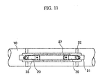
Next, an embodiment 3 of the ultrasonic flow measuring device will be described with reference to
Figs. 10 to 14. Fig. 10 is a front view showing the embodiment 3 of the ultrasonic flow measuring
device according to this invention, Fig. 11 is a plan view of the ultrasonic transducer shown in Fig.
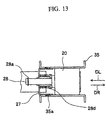
10 which is viewed from the lower side, Fig. 12 is an enlarged view showing the details of the
surrounding of the positioning shaft of the ultrasonic transducer of Fig. 11, Fig. 13 is a cross-sectional
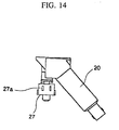
view taken along a line Y-Y of Fig. 12, and Fig. 14 is an enlarged view showing the details
of a sub assembly state of the ultrasonic transducer shown in Fig. 10.
The ultrasonic flow measuring device 103 shown in Figs. 10 and 11 basically has the same
construction as the ultrasonic flow measuring devices 101 and 102 described previously, however, it
has a different fixing mechanism of the ultrasonic transducers 20 as described below. That is, the
guide frame 35 of the ultrasonic flow measuring device 103 has plural positioning holes 35a formed
in a row on the side surface. A coil spring 28d and a positioning metal fitting 27 are mounted on the
positioning shaft 28 of each ultrasonic transducer 20, and they are fixed by an E ring 28a so as not
to drop out of the positioning shaft 28.
The ultrasonic transducer 20, the coil spring 28d and the positioning metal fitting 27 described above
are pre-assembled as shown in Fig. 14. In this case, the positioning metal fitting 27 is preferably
formed of a plate member having elasticity. The assembly as shown in Fig. 14 is inserted into the
guide frame 35. In this case, the positioning projection(s) 27a of the positioning metal fitting 27
is(are) fitted in the positioning holes 35a of the guide frame 35 (see Figs. 12, 13, and 14), and
assembled as shown in Figs. 10 and 11. In order to fit easily the positioning projection(s) 27a into
the proper positioning hole(s) 35a, slits 27b are formed in the positioning metal fitting 27, and
graduations 35b are formed on the upper portion of the guide frame 35. At the time of this assembly,
the acoustic coupling medium 29 is coated on the bottom surfaces of the ultrasonic transducers 20.
When the assembly is properly carried out as described above, the ultrasonic transducers 20 are
freely movable in the directions of the arrows DL, DR in Fig. 13 in the guide frame 35. Accordingly,
when the transceiver sub-assembly shown in Fig. 14 is installed in the guide frame 35, the ultrasonic
transducer 20 is urged by the compressed coil spring 28d to move in the direction of the arrow DR,
and the bottom surface thereof abuts against the surface of the conduit pipe 10. Accordingly, the
transceiver sub-assemblies can be mounted to the guide frame 35 through one-touch operation, and
it is not so difficult to detach them from the guide frame 35. The point that the work can be divided
and the advantage achieved by this point are the same as with the ultrasonic flow measuring devices
101 and 102.
INDUSTRIAL APPLICABILITY
The ultrasonic flow measuring device of this invention is constructed as described above. Therefore,
the positioning mechanism can determine the positions of the ultrasonic transducers every desired
interval, and if the optimum positioning is selected, the regular orientation and position can be
automatically applied to the ultrasonic transducers. Furthermore, the fixing of the guide frame to the
conduit pipe and the fixing of the ultrasonic transducers to the positioning frame can be carried out
as different works, and thus the operation efficiency is high. For example, since it is unnecessary to
coat the acoustic coupling medium on the conduit pipe at the time when the guide frame is fixed to
the conduit pipe, selection of the setup place, the movement and the positioning of the guide frame
can be freely performed. Furthermore, when the ultrasonic transducers are secured, they are
positioned by using the positioning springs and the positioning holes, so that the positioning of the
ultrasonic transducers can be easily performed. Still furthermore, when the positioning means having
the positioning projection is used, the mounting of the ultrasonic transducers onto the guide frame
can be performed through one-touch operation, and thus it is very efficient.
Description of Reference Numerals
10 conduit pipe, 20 ultrasonic transducer, 25, 26, 27 positioning metal fitting, 25a, 26c press plate,
25b positioning spring, 26a press fitting, 26b fixing pin, 27a positioning projection, 27b slit, 28
positioning shaft, 28a E ring, 28b coil spring, 28c disc spring, 29 acoustic coupling medium, 30, 35
guide frame, 31 saddle, 32 belt, 35b graduations, 35a positioning hole, 40, 50 positioning frame, 41,
51 positioning portion, 43 fixing screw, 101, 102, 103 ultrasonic flow measuring device.