EP1396692A1 - Ice maker - Google Patents
Ice maker Download PDFInfo
- Publication number
- EP1396692A1 EP1396692A1 EP03251952A EP03251952A EP1396692A1 EP 1396692 A1 EP1396692 A1 EP 1396692A1 EP 03251952 A EP03251952 A EP 03251952A EP 03251952 A EP03251952 A EP 03251952A EP 1396692 A1 EP1396692 A1 EP 1396692A1
- Authority
- EP
- European Patent Office
- Prior art keywords
- feeding
- ice making
- ice
- tray cells
- pulleys
- Prior art date
- Legal status (The legal status is an assumption and is not a legal conclusion. Google has not performed a legal analysis and makes no representation as to the accuracy of the status listed.)
- Withdrawn
Links
Images


Classifications
-
- F—MECHANICAL ENGINEERING; LIGHTING; HEATING; WEAPONS; BLASTING
- F25—REFRIGERATION OR COOLING; COMBINED HEATING AND REFRIGERATION SYSTEMS; HEAT PUMP SYSTEMS; MANUFACTURE OR STORAGE OF ICE; LIQUEFACTION SOLIDIFICATION OF GASES
- F25C—PRODUCING, WORKING OR HANDLING ICE
- F25C1/00—Producing ice
- F25C1/22—Construction of moulds; Filling devices for moulds
-
- F—MECHANICAL ENGINEERING; LIGHTING; HEATING; WEAPONS; BLASTING
- F25—REFRIGERATION OR COOLING; COMBINED HEATING AND REFRIGERATION SYSTEMS; HEAT PUMP SYSTEMS; MANUFACTURE OR STORAGE OF ICE; LIQUEFACTION SOLIDIFICATION OF GASES
- F25C—PRODUCING, WORKING OR HANDLING ICE
- F25C1/00—Producing ice
- F25C1/10—Producing ice by using rotating or otherwise moving moulds
-
- A—HUMAN NECESSITIES
- A23—FOODS OR FOODSTUFFS; TREATMENT THEREOF, NOT COVERED BY OTHER CLASSES
- A23G—COCOA; COCOA PRODUCTS, e.g. CHOCOLATE; SUBSTITUTES FOR COCOA OR COCOA PRODUCTS; CONFECTIONERY; CHEWING GUM; ICE-CREAM; PREPARATION THEREOF
- A23G9/00—Frozen sweets, e.g. ice confectionery, ice-cream; Mixtures therefor
- A23G9/04—Production of frozen sweets, e.g. ice-cream
- A23G9/14—Continuous production
-
- F—MECHANICAL ENGINEERING; LIGHTING; HEATING; WEAPONS; BLASTING
- F25—REFRIGERATION OR COOLING; COMBINED HEATING AND REFRIGERATION SYSTEMS; HEAT PUMP SYSTEMS; MANUFACTURE OR STORAGE OF ICE; LIQUEFACTION SOLIDIFICATION OF GASES
- F25C—PRODUCING, WORKING OR HANDLING ICE
- F25C5/00—Working or handling ice
- F25C5/02—Apparatus for disintegrating, removing or harvesting ice
- F25C5/04—Apparatus for disintegrating, removing or harvesting ice without the use of saws
- F25C5/08—Apparatus for disintegrating, removing or harvesting ice without the use of saws by heating bodies in contact with the ice
Definitions
- the present invention relates to an ice maker, and more particularly, to an ice maker provided with an ice making conveyor.
- refrigerators or automatic dispensers are equipped with ice makers and are adapted to make ice using water supplied thereto.
- the conventional ice maker includes a pair of rollers, that is, a drive roller 1 and a driven roller 2, spaced apart from each other by a desired distance, a motor actuator 3 equipped with a motor (not shown), and adapted to rotate the drive roller 1, and an ice making belt 4 wound around the drive and driven rollers 1 and 2.
- the ice making belt 4 is provided with ice making recesses 5 made of a flexible material.
- the ice making belt 4 has engagement holes 6 formed along lateral edges thereof, whereas each of the drive and driven rollers 1 and 2 is provided with engagement protrusions 7 engagable with the engagement holes 6.
- the ice making belt 4 can receive drive power from the drive roller 1 in accordance with the engagement between the engagement holes 6 and engagement protrusions 7.
- those ice making recesses 5 are made of a thin synthetic resin structure such as a film to provide a desired flexibility.
- the recesses may be easily damaged due to being subjected to a repeated deformation in accordance with repeated ice making and separating processes.
- the ice maker is typically installed in a freezing chamber maintained at a low temperature state to freeze water, the hardening of the ice making recesses 5 is accelerated by cold air in the freezing chamber. For this reason, the possibility of damage to the ice making recesses 5 is further increased.
- an aim of the present invention is to provide an ice maker capable of preventing ice making recesses from being damaged.
- prevention of damage to the ice making recesses is accomplished by providing an ice maker that includes a pair of pulleys spaced apart from each other by a desired distance, a drive unit rotating the pulleys, a plurality of tray cells provided with ice making recesses capable of containing water, and an ice making conveyor formed by the tray cells coupled to one another, where the ice making conveyor is wound around the pulleys.
- the ice making recesses may be made substantially of a rigid body to prevent being deformed even when subjected to an external force.
- each of the tray cells is made of a metal material and includes an ice making section provided with at least one of the ice making recesses and a feeding section that is adapted to support the ice making section and is hingeably coupled at opposite ends thereof to the tray cells arranged adjacent thereto.
- the feeding section receives drive power from the pulleys and moves around the pulleys along with the ice making section.
- each of the tray cells is provided at opposite ends thereof with a hinge protrusion and a hinge hole, respectively.
- the hinge protrusion and the hinge hole are coupled with a hinge hole provided at an adjacent one of the tray cells and a hinge protrusion provided at another adjacent one of the tray cells, respectively.
- the feeding section has a pair of feeding plates spaced apart from each other by a predetermined desired distance to obtain a desired width of the feeding section and a support pin that has opposite ends supported by the feeding plates while maintaining a desired distance between the feeding plates.
- each of the feeding plates has opposite ends, each having an arc shape with a desired radius of curvature.
- One of the ends of the feeding plate has a width that is less than a width of the other end of the feeding plate and is coupled to the other end of an adjacent feeding plate inside the adjacent feeding plate.
- the ice maker may further comprise a heater arranged inside the ice making conveyor, where the heater is adapted to apply heat to at least a part of the tray cells that have ice making recesses facing downward to separate ice from the tray cells.
- the tray cells may be provided with feeding protrusions or feeding grooves engageable with the feeding protrusions, and the pulleys may be provided with those of the feeding protrusions and feeding grooves not provided at the tray cells, so that the tray cells receive a force from the pulleys via the feeding protrusions and the feeding grooves.
- FIG. 2 and 3 an ice maker according to an embodiment of the present invention is illustrated.
- a pair of pulleys 10a and 10b are spaced apart from each other by a desired distance.
- a drive unit 20 is utilized for rotating the pulleys 10a and 10b, and an ice making conveyer 30 is wound around the pulleys 10a and 10b.
- the pulley 10a is a drive pulley adapted to rotate by drive power transmitted from the drive unit 20, and the pulley 10b is a driven pulley adapted to rotate by the drive power transmitted from the drive pulley 10a.
- the drive and driven pulleys 10a and 10b are mounted to opposite ends of a support bracket 11 and are spaced apart from each other by a desired distance by virtue of the support bracket 11.
- the ice making conveyer 30 includes a plurality of tray cells 40 connected to one another to form an endless conveyer. As shown in Figure 4, each tray cell 40 includes an ice making section 41 provided with at least one ice making recess 41a for containing water to be frozen. A feeding section 42 of each tray cell 40 is adapted to support the ice making section 41 while moving around the pulleys 10a and 10b along with the ice making recess 41a in accordance with the drive power transmitted from the drive pulley 10a.
- the ice making section 41 is provided with a pair of ice making recesses 41a, each made of a rigid body having a desired strength to prevent deformation or damage.
- the ice making section 41 and ice making recesses 41a are made of a metal material, for example, stainless steel. Accordingly, the present invention prevents deformation and damage of the ice making section 41 and ice making recesses 41a while allowing an easy transmission of heat and cold air.
- each feeding section 42 includes a pair of feeding plates 42a, and a support pin 42b connecting the feeding plates 42a, while maintaining a predetermined desired distance between the feeding plates 42a.
- Each feeding plate 42a is provided at opposite ends thereof with a hinge protrusion 42c and a hinge hole 42d, respectively, to provide coupling to adjacent ones of the tray cells.
- the hinge protrusion 42c is provided at an upstream end of an associated feeding plate 42a, whereas the hinge hole 42d is provided at a downstream end of the associated feeding plate 42a.
- the hinge protrusion 42c of one tray cell 40 is coupled to the hinge hole 42d of a tray cell 40 that is adjacent to the one tray cell 40, whereas the hinge hole 42d of the one tray cell 40 is coupled to the hinge protrusion 42c of a next tray cell 40.
- Each feeding plate 42a has, at its both ends, an arc shape having a desired radius of curvature to allow the ice making conveyor 30 to rotate smoothly while being bent along the circumferential surfaces of the drive and driven pulleys 10a and 10b.
- the end of each feeding plate 42a provided with the hinge protrusion 42c has a width that is less than a width of the end of the corresponding feeding plate 42a provided with the hinge hole 42d to permit coupling, inside the adjacent feeding plate 42a, to the end of the adjacent feeding plate 42a provided with the hinge hole 42d.
- each tray cell 40 In order to make each tray cell 40 easily receive the drive power from the drive pulley 10a, a feeding protrusion 42e is protruded from each feeding plate 42a of the feeding section 42.
- Each of the drive and driven pulleys 10a and 10b is provided at its circumferential surface with a plurality of uniformly spaced feeding grooves 10c ( Figure 3) adapted to engage with the feeding protrusions 42e of the feeding plates 42a. Accordingly, the drive power from the drive pulley 10a is transmitted to the tray cells 40 via the feeding protrusions 42e and feeding grooves 10c, to rotate the tray cells 40 around the drive and driven pulleys 10a and 10b.
- the ice maker of the present invention further includes a heater 50 for separating ice from the ice making section 41.
- the heater 50 is arranged beneath the support bracket 11 to generate heat when it receives electric power and heat the tray cells 40 with the ice making recesses facing downward.
- the ice maker may be installed in a freezing chamber with both ends of its support bracket 11 supported by the inner wall of the freezing chamber.
- a U-shaped fixing bracket 60 is fixedly mounted to the inner wall of the freezing chamber to support the ice maker by supporting each end of the support bracket 11 at opposite lateral sides of the support bracket 11.
- a storage tray 70 is arranged beneath the ice maker in order to contain the ice made by the ice maker.
- a water supply tube 80 is arranged over the ice maker to supply water to the tray cells 40.
- each feeding protrusion 42e is provided at an associated tray cell 40, and the feeding grooves 10c are provided at each of the pulleys 10a and 10b.
- the feeding grooves 10c it is possible to provide the feeding grooves 10c at the tray cells 40 while providing the feeding protrusions 42e at the pulleys 10a and 10b.
- water is supplied, via the water supply tube 80, to the tray cells 40 with the ice making recesses 40a facing upward. Since the ice maker is arranged in the freezing chamber of a refrigerator, cold air freezes the water in the ice making recesses 41a after a desired time elapses.
- the ice making conveyor 30 is moved in accordance with operations of the drive unit 20 and two pulleys 10a and 10b. That is, when the drive unit 20 operates by electric power applied thereto, the drive pulley 10a is rotated, moving the ice making conveyer 30 in accordance with the engagement between the feeding grooves 10c provided at the circumferential surface of the drive pulley 10a and the feeding protrusions 42e provided at the tray cells 40.
- the ice-made tray cells 40 are positioned beneath the heater 50, heat generated from the heater 50 is applied to the tray cells 40 to heat the ice making section 41 and ice making recesses 41a of the tray cells 40.
- each ice making recess 41a is thawed at a surface contacting the ice making recess 41a by the heat transmitted from the heater 50 to separate the ice from the ice making recess 41a by a weight of the ice. As a result, the ice falls downward and is stored in the storage tray 70.
- the ice maker of the present invention exhibits a reduced occurrence of damage even after a prolonged use because the ice making recesses have a rigid body made of a durable material such as metal.
- heat or cold air is easily transmitted to water or ice received in the ice making recesses because the material of the ice making recesses exhibits a superior thermal transfer rate as compared to synthetic resin materials. Accordingly, the ice maker of the present invention provides convenient ice making and separating processes.
Landscapes
- Engineering & Computer Science (AREA)
- Physics & Mathematics (AREA)
- Mechanical Engineering (AREA)
- Thermal Sciences (AREA)
- General Engineering & Computer Science (AREA)
- Manufacturing & Machinery (AREA)
- Life Sciences & Earth Sciences (AREA)
- Chemical & Material Sciences (AREA)
- Food Science & Technology (AREA)
- Polymers & Plastics (AREA)
- Devices That Are Associated With Refrigeration Equipment (AREA)
- Production, Working, Storing, Or Distribution Of Ice (AREA)
Abstract
An ice maker includes a pair of pulleys (10a,10b)
spaced apart from each other by a desired distance, a
drive unit (20) rotating the pulleys, a plurality of tray
cells (40) provided with ice making recesses (41a) capable
of containing water, and an ice making conveyor (30)
formed by the tray cells (40) coupled to one another, the
ice making conveyor (30) being wound around the pulleys.
Ice making recesses (41a) are formed by a rigid body made
of a metal material. A heater (50) is arranged to apply
heat to the tray cells (40), thereby separating ice from
the tray cells (40). Accordingly, the ice maker exhibits
a reduced occurrence of damage during ice making and
separating processes while having an effect of achieving
easy ice making and separating processes.
Description
- The present invention relates to an ice maker, and more particularly, to an ice maker provided with an ice making conveyor.
- As is well known, refrigerators or automatic dispensers are equipped with ice makers and are adapted to make ice using water supplied thereto.
- Referring to Figure 1, a conventional ice maker is illustrated which is disclosed in Japanese Patent Laid-open Publication No. 2000-88414. As shown in Figure 1, the conventional ice maker includes a pair of rollers, that is, a
drive roller 1 and a driven roller 2, spaced apart from each other by a desired distance, amotor actuator 3 equipped with a motor (not shown), and adapted to rotate thedrive roller 1, and anice making belt 4 wound around the drive and drivenrollers 1 and 2. Theice making belt 4 is provided withice making recesses 5 made of a flexible material. - The
ice making belt 4 hasengagement holes 6 formed along lateral edges thereof, whereas each of the drive and drivenrollers 1 and 2 is provided withengagement protrusions 7 engagable with theengagement holes 6. Theice making belt 4 can receive drive power from thedrive roller 1 in accordance with the engagement between theengagement holes 6 andengagement protrusions 7. - When the
motor actuator 3 is operated to rotate thedrive roller 1, ice is made in accordance with the freezing of water in the ice makingrecesses 5 provided at theice making belt 4, and thedrive roller 1 deforms the shape of theice making recesses 5 made of a flexible material, thereby causing ice to be separated from the ice makingrecesses 5. - For such a separation of ice from the
ice making recesses 5 in the above mentioned ice maker, thoseice making recesses 5 are made of a thin synthetic resin structure such as a film to provide a desired flexibility. However, where theice making recesses 5 are made of a thin synthetic resin structure having flexibility, the recesses may be easily damaged due to being subjected to a repeated deformation in accordance with repeated ice making and separating processes. In particular, since the ice maker is typically installed in a freezing chamber maintained at a low temperature state to freeze water, the hardening of the ice makingrecesses 5 is accelerated by cold air in the freezing chamber. For this reason, the possibility of damage to the ice makingrecesses 5 is further increased. - Therefore, an aim of the present invention is to provide an ice maker capable of preventing ice making recesses from being damaged.
- Other aims and advantages of the invention will be set forth in part in the description which follows and, in part, will be obvious from the description, or may be learned by practice of the invention.
- According to the present invention there is provided an apparatus and method as set forth in the appended claims. Preferred features of the invention will be apparent from the dependent claims, and the description which follows.
- In one aspect of the present invention, prevention of damage to the ice making recesses is accomplished by providing an ice maker that includes a pair of pulleys spaced apart from each other by a desired distance, a drive unit rotating the pulleys, a plurality of tray cells provided with ice making recesses capable of containing water, and an ice making conveyor formed by the tray cells coupled to one another, where the ice making conveyor is wound around the pulleys.
- The ice making recesses may be made substantially of a rigid body to prevent being deformed even when subjected to an external force.
- Preferably, each of the tray cells is made of a metal material and includes an ice making section provided with at least one of the ice making recesses and a feeding section that is adapted to support the ice making section and is hingeably coupled at opposite ends thereof to the tray cells arranged adjacent thereto. The feeding section receives drive power from the pulleys and moves around the pulleys along with the ice making section.
- Preferably, each of the tray cells is provided at opposite ends thereof with a hinge protrusion and a hinge hole, respectively. The hinge protrusion and the hinge hole are coupled with a hinge hole provided at an adjacent one of the tray cells and a hinge protrusion provided at another adjacent one of the tray cells, respectively.
- Preferably, the feeding section has a pair of feeding plates spaced apart from each other by a predetermined desired distance to obtain a desired width of the feeding section and a support pin that has opposite ends supported by the feeding plates while maintaining a desired distance between the feeding plates.
- Preferably, each of the feeding plates has opposite ends, each having an arc shape with a desired radius of curvature. One of the ends of the feeding plate has a width that is less than a width of the other end of the feeding plate and is coupled to the other end of an adjacent feeding plate inside the adjacent feeding plate.
- The ice maker may further comprise a heater arranged inside the ice making conveyor, where the heater is adapted to apply heat to at least a part of the tray cells that have ice making recesses facing downward to separate ice from the tray cells.
- The tray cells may be provided with feeding protrusions or feeding grooves engageable with the feeding protrusions, and the pulleys may be provided with those of the feeding protrusions and feeding grooves not provided at the tray cells, so that the tray cells receive a force from the pulleys via the feeding protrusions and the feeding grooves.
- For a better understanding of the invention, and to show how embodiments of the same may be carried into effect, reference will now be made, by way of example, to the accompanying diagrammatic drawings in which:
- Figure 1 is a perspective view illustrating a conventional ice maker;
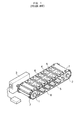
- Figure 2 is a perspective view illustrating the configuration of an ice maker according to an embodiment of the present invention;
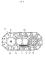
- Figure 3 is a side view illustrating the ice maker according to of Figure 2; and
- Figure 4 is a perspective view illustrating the configuration of tray cells included in the ice maker of Figure 2.
-
- Referring to Figures 2 and 3, an ice maker according to an embodiment of the present invention is illustrated. A pair of
pulleys drive unit 20 is utilized for rotating thepulleys ice making conveyer 30 is wound around thepulleys - The
pulley 10a is a drive pulley adapted to rotate by drive power transmitted from thedrive unit 20, and thepulley 10b is a driven pulley adapted to rotate by the drive power transmitted from thedrive pulley 10a. The drive and drivenpulleys support bracket 11 and are spaced apart from each other by a desired distance by virtue of thesupport bracket 11. - The
ice making conveyer 30 includes a plurality oftray cells 40 connected to one another to form an endless conveyer. As shown in Figure 4, eachtray cell 40 includes anice making section 41 provided with at least one ice makingrecess 41a for containing water to be frozen. Afeeding section 42 of eachtray cell 40 is adapted to support theice making section 41 while moving around thepulleys recess 41a in accordance with the drive power transmitted from thedrive pulley 10a. - In the illustrated embodiment, the
ice making section 41 is provided with a pair ofice making recesses 41a, each made of a rigid body having a desired strength to prevent deformation or damage. As shown in Figure 4, theice making section 41 andice making recesses 41a are made of a metal material, for example, stainless steel. Accordingly, the present invention prevents deformation and damage of theice making section 41 andice making recesses 41a while allowing an easy transmission of heat and cold air. - Meanwhile, each
feeding section 42 includes a pair offeeding plates 42a, and asupport pin 42b connecting thefeeding plates 42a, while maintaining a predetermined desired distance between thefeeding plates 42a. Eachfeeding plate 42a is provided at opposite ends thereof with ahinge protrusion 42c and ahinge hole 42d, respectively, to provide coupling to adjacent ones of the tray cells. As shown in Figure 4, thehinge protrusion 42c is provided at an upstream end of an associatedfeeding plate 42a, whereas thehinge hole 42d is provided at a downstream end of the associatedfeeding plate 42a. Thehinge protrusion 42c of onetray cell 40 is coupled to thehinge hole 42d of atray cell 40 that is adjacent to the onetray cell 40, whereas thehinge hole 42d of the onetray cell 40 is coupled to thehinge protrusion 42c of anext tray cell 40. Thus, theice making conveyer 30, which has an endless structure, is obtained. - Each
feeding plate 42a has, at its both ends, an arc shape having a desired radius of curvature to allow theice making conveyor 30 to rotate smoothly while being bent along the circumferential surfaces of the drive and drivenpulleys feeding plate 42a provided with thehinge protrusion 42c has a width that is less than a width of the end of thecorresponding feeding plate 42a provided with thehinge hole 42d to permit coupling, inside theadjacent feeding plate 42a, to the end of theadjacent feeding plate 42a provided with thehinge hole 42d. - In order to make each
tray cell 40 easily receive the drive power from thedrive pulley 10a, afeeding protrusion 42e is protruded from eachfeeding plate 42a of thefeeding section 42. Each of the drive and drivenpulleys feeding grooves 10c (Figure 3) adapted to engage with thefeeding protrusions 42e of thefeeding plates 42a. Accordingly, the drive power from thedrive pulley 10a is transmitted to thetray cells 40 via thefeeding protrusions 42e and feedinggrooves 10c, to rotate thetray cells 40 around the drive and drivenpulleys - Referring again to Figure 3, the ice maker of the present invention further includes a
heater 50 for separating ice from theice making section 41. Theheater 50 is arranged beneath thesupport bracket 11 to generate heat when it receives electric power and heat thetray cells 40 with the ice making recesses facing downward. - The ice maker may be installed in a freezing chamber with both ends of its
support bracket 11 supported by the inner wall of the freezing chamber. As shown in the embodiment of Figure 2, aU-shaped fixing bracket 60 is fixedly mounted to the inner wall of the freezing chamber to support the ice maker by supporting each end of thesupport bracket 11 at opposite lateral sides of thesupport bracket 11. - A
storage tray 70 is arranged beneath the ice maker in order to contain the ice made by the ice maker. Awater supply tube 80 is arranged over the ice maker to supply water to thetray cells 40. - As shown in Figures 3 and 4, each
feeding protrusion 42e is provided at an associatedtray cell 40, and thefeeding grooves 10c are provided at each of thepulleys feeding grooves 10c at thetray cells 40 while providing thefeeding protrusions 42e at thepulleys - The operation, function and effect of the ice maker having the above described configuration will be described in detail.
- First, water is supplied, via the
water supply tube 80, to thetray cells 40 with the ice making recesses 40a facing upward. Since the ice maker is arranged in the freezing chamber of a refrigerator, cold air freezes the water in the ice makingrecesses 41a after a desired time elapses. - In order to separate the ice from the
tray cells 40, theice making conveyor 30 is moved in accordance with operations of thedrive unit 20 and twopulleys drive unit 20 operates by electric power applied thereto, thedrive pulley 10a is rotated, moving theice making conveyer 30 in accordance with the engagement between the feedinggrooves 10c provided at the circumferential surface of thedrive pulley 10a and the feedingprotrusions 42e provided at thetray cells 40. When the ice-madetray cells 40 are positioned beneath theheater 50, heat generated from theheater 50 is applied to thetray cells 40 to heat theice making section 41 andice making recesses 41a of thetray cells 40. The ice made in eachice making recess 41a is thawed at a surface contacting theice making recess 41a by the heat transmitted from theheater 50 to separate the ice from theice making recess 41a by a weight of the ice. As a result, the ice falls downward and is stored in thestorage tray 70. - As is apparent from the above description, the ice maker of the present invention exhibits a reduced occurrence of damage even after a prolonged use because the ice making recesses have a rigid body made of a durable material such as metal. In particular, heat or cold air is easily transmitted to water or ice received in the ice making recesses because the material of the ice making recesses exhibits a superior thermal transfer rate as compared to synthetic resin materials. Accordingly, the ice maker of the present invention provides convenient ice making and separating processes.
- Although a few preferred embodiments have been shown and described, it will be appreciated by those skilled in the art that various changes and modifications might be made without departing from the scope of the invention, as defined in the appended claims.
- Attention is directed to all papers and documents which are filed concurrently with or previous to this specification in connection with this application and which are open to public inspection with this specification, and the contents of all such papers and documents are incorporated herein by reference.
- All of the features disclosed in this specification (including any accompanying claims, abstract and drawings), and/or all of the steps of any method or process so disclosed, may be combined in any combination, except combinations where at least some of such features and/or steps are mutually exclusive.
- Each feature disclosed in this specification (including any accompanying claims, abstract and drawings) may be replaced by alternative features serving the same, equivalent or similar purpose, unless expressly stated otherwise. Thus, unless expressly stated otherwise, each feature disclosed is one example only of a generic series of equivalent or similar features.
- The invention is not restricted to the details of the foregoing embodiment(s). The invention extends to any novel one, or any novel combination, of the features disclosed in this specification (including any accompanying claims, abstract and drawings), or to any novel one, or any novel combination, of the steps of any method or process so disclosed.
Claims (12)
- An ice maker comprising:wherein the ice making recesses (41a) are substantially made of a rigid body so that they are not deformed even when they are subjected to an external force .a pair of pulleys (10a,10b) spaced apart from each other by a desired distance;a drive unit (20) for rotating the pulleys (10a,10b);a plurality of tray cells (40) provided with ice making recesses (41a) to contain water; andan ice making conveyor (30) formed by the tray cells (40) coupled to one another, the ice making conveyor (30) being wound around the pulleys (10a,10b),
- The ice maker according to claim 1, wherein each of the tray cells (40) is made of a metal material and includes an ice making section (41) provided with at least one of the ice making recesses (41a) and a feeding section (42) that is adapted to support the ice making section and is hingeably coupled at opposite ends thereof to adjacent tray cells (40), the feeding section (42) and the ice making section receiving drive power from the pulleys (10a,10b) to move around the pulleys (10a,10b).
- The ice maker according to claim 2, wherein each of the tray cells (40) is provided at opposite ends thereof with a hinge protrusion (42c) and a hinge hole (42d), respectively, to couple the hinge protrusion (42c) with a hinge hole (42d) provided at an adjacent one of the tray cells (40) and to couple the hinge hole with a hinge protrusion (42c) provided at another adjacent one of the tray cells (40), respectively.
- The ice maker according to claim 3, wherein the feeding section (42) comprises a pair of feeding plates (42a) spaced apart by a predetermined desired distance to obtain a desired width of the feeding section (42) and a support pin (42b) having opposite ends supported by the feeding plates (42a) while maintaining the predetermined distance between the feeding plates (42a).
- The ice maker according to claim 4, wherein each of the feeding plates (42a) has opposite ends, each end having an arc shape with a desired radius of curvature, and one of the ends of the feeding plate has a width less than a width of the other end of the feeding plate to couple inside the adjacent feeding plate by coupling to a wider end of an adjacent one of the feeding plates (42a) .
- The ice maker according to any preceding claim, further comprising:a heater (50) arranged inside the ice making conveyor (30) to apply heat to at least a part of the tray cells (40) with the ice making recesses (41a) facing downward to separate ice from the tray cells (40).
- The ice maker according to any preceding claim, wherein the tray cells (40) are provided with one of feeding protrusions (42c) and feeding grooves (10c), and the pulleys (10a,10b) are provided with the other of the feeding grooves and feeding protrusions (42c) not provided at the tray cells (40) to provide a force from the pulleys (10a,10b) via the feeding protrusions (42c) and the feeding grooves (10c).
- An ice making conveyor (30) comprising:a plurality of metal tray cells (40) having rigid ice making recesses (41a);a looped pulley section (30) having the metal tray cells (40) disposed therein;a drive unit (10,20) to drive the looped pulley section (30); anda heater (50), disposed beneath a portion of the looped pulley section, to heat proximate metal tray cells (40) in an upside down orientation to release at least some ice from the metal tray cells (40).
- The ice making conveyor (30) according to claim 8, wherein each of the tray cells (40) is provided at opposite ends thereof with a hinge protrusion (42c) and a hinge hole, respectively, to couple the hinge protrusion (42c) with a hinge hole provided at an adjacent one of the tray cells (40) and to couple the hinge hole with a hinge protrusion (42c) provided at another adjacent one of the tray cells (40), respectively.
- The ice maker according to claim 9, wherein the tray cells (40) include a feeding section (42) having a pair of feeding plates (42a) separated by a predetermined desired distance to obtain a desired width of the feeding section (42) and a support pin (42b) having opposite ends supported by the feeding plates (42a) while maintaining the predetermined distance between the feeding plates (42a).
- The ice making conveyor (30) according to claim 10, wherein each of the feeding plates (42a) has opposite ends, each end having an arc shape with a desired radius of curvature, and one of the ends of the feeding plate has a width less than a width of the other end of the feeding plate to couple inside the adjacent feeding plate by coupling to a wider end of an adjacent one of the feeding plates (42a) .
- The ice making conveyor (30) according to any of claims 8 to 11, wherein the tray cells (40) and the drive unit (10,20) are provided complimentary feeding grooves (10c) and feeding protrusions (42c) .
Applications Claiming Priority (2)
| Application Number | Priority Date | Filing Date | Title |
|---|---|---|---|
| KR10-2002-0052314A KR100490205B1 (en) | 2002-08-31 | 2002-08-31 | Ice maker |
| KR2002052314 | 2002-08-31 |
Publications (1)
| Publication Number | Publication Date |
|---|---|
| EP1396692A1 true EP1396692A1 (en) | 2004-03-10 |
Family
ID=31713172
Family Applications (1)
| Application Number | Title | Priority Date | Filing Date |
|---|---|---|---|
| EP03251952A Withdrawn EP1396692A1 (en) | 2002-08-31 | 2003-03-27 | Ice maker |
Country Status (4)
| Country | Link |
|---|---|
| US (1) | US6792770B2 (en) |
| EP (1) | EP1396692A1 (en) |
| KR (1) | KR100490205B1 (en) |
| CN (1) | CN1231734C (en) |
Families Citing this family (7)
| Publication number | Priority date | Publication date | Assignee | Title |
|---|---|---|---|---|
| EP2216613A1 (en) * | 2009-02-09 | 2010-08-11 | Dometic Sweden AB | Ice maker and method of producing pieces of ice |
| KR20140075291A (en) * | 2012-12-11 | 2014-06-19 | 동부대우전자 주식회사 | Refrigerator |
| CN107883627A (en) * | 2017-12-15 | 2018-04-06 | 江苏高菱蓄能科技有限公司 | One kind automation ice maker |
| KR102317462B1 (en) * | 2020-02-27 | 2021-10-27 | 구하서 | Ice manufacturing device |
| KR102116881B1 (en) * | 2020-02-27 | 2020-05-29 | (주)제이엘피엔지니어링 | System for rapidly making continuous-circulating small-sized ice for industry |
| KR102243639B1 (en) * | 2020-07-09 | 2021-04-26 | 주식회사 프로팩코리아 | Automatic ice making apparatus |
| CN113188280B (en) * | 2021-05-10 | 2022-08-30 | 大英县浩翔种养殖专业合作社 | Cold storage uniform-temperature intelligent fresh-keeping device and fresh-keeping method thereof |
Citations (6)
| Publication number | Priority date | Publication date | Assignee | Title |
|---|---|---|---|---|
| US2385539A (en) * | 1945-09-25 | Automatic ice freezing unit and method | ||
| US2531087A (en) * | 1945-11-28 | 1950-11-21 | Tharaldsen Tharald Warberg | Freezing apparatus |
| US2664592A (en) * | 1951-09-14 | 1954-01-05 | Allied Chem & Dye Corp | Conveyer |
| US2718124A (en) * | 1953-06-01 | 1955-09-20 | Thomas B Gilliam | Ice cube apparatus and method |
| JP2000088414A (en) | 1998-09-11 | 2000-03-31 | Calsonic Corp | Automatic ice maker |
| US20010027654A1 (en) * | 1999-10-08 | 2001-10-11 | Shapiro Andrew Philip | Icemaker assembly |
Family Cites Families (13)
| Publication number | Priority date | Publication date | Assignee | Title |
|---|---|---|---|---|
| US2765A (en) * | 1842-08-31 | Francis degbn | ||
| US2054074A (en) * | 1930-05-23 | 1936-09-15 | Flakice Corp | Ice making and apparatus |
| US2381069A (en) * | 1943-06-01 | 1945-08-07 | Lutes Herschel | Refrigerating apparatus |
| US3253425A (en) * | 1964-05-28 | 1966-05-31 | Burleigh H Mckissick | Endless flexible belt type ice cube maker |
| JPS4630436Y1 (en) * | 1968-06-13 | 1971-10-21 | ||
| KR950004397Y1 (en) * | 1992-06-05 | 1995-05-30 | 이헌조 | Ice machine using on refrigerator |
| US5425248A (en) * | 1994-06-27 | 1995-06-20 | General Electric Company | Ice maker subassembly for a refrigerator freezer |
| KR970016436A (en) * | 1995-09-18 | 1997-04-28 | 배순훈 | Refrigerated Ice Maker for Refrigerator |
| JP3781470B2 (en) * | 1996-03-12 | 2006-05-31 | 松下冷機株式会社 | Automatic ice making equipment |
| KR19990037461U (en) * | 1998-03-06 | 1999-10-05 | 윤종용 | Refrigerator ice container |
| US6196016B1 (en) | 1999-05-21 | 2001-03-06 | Bright Solutions, Inc. | Multiple-dose, flush-through injector |
| WO2001027544A2 (en) * | 1999-10-08 | 2001-04-19 | General Electric Company | Icemaker assembly |
| US6349550B1 (en) * | 2001-06-25 | 2002-02-26 | General Electric Company | Ice transformation detection |
-
2002
- 2002-08-31 KR KR10-2002-0052314A patent/KR100490205B1/en not_active Expired - Fee Related
-
2003
- 2003-03-18 CN CNB03121617XA patent/CN1231734C/en not_active Expired - Fee Related
- 2003-03-25 US US10/395,096 patent/US6792770B2/en not_active Expired - Fee Related
- 2003-03-27 EP EP03251952A patent/EP1396692A1/en not_active Withdrawn
Patent Citations (6)
| Publication number | Priority date | Publication date | Assignee | Title |
|---|---|---|---|---|
| US2385539A (en) * | 1945-09-25 | Automatic ice freezing unit and method | ||
| US2531087A (en) * | 1945-11-28 | 1950-11-21 | Tharaldsen Tharald Warberg | Freezing apparatus |
| US2664592A (en) * | 1951-09-14 | 1954-01-05 | Allied Chem & Dye Corp | Conveyer |
| US2718124A (en) * | 1953-06-01 | 1955-09-20 | Thomas B Gilliam | Ice cube apparatus and method |
| JP2000088414A (en) | 1998-09-11 | 2000-03-31 | Calsonic Corp | Automatic ice maker |
| US20010027654A1 (en) * | 1999-10-08 | 2001-10-11 | Shapiro Andrew Philip | Icemaker assembly |
Also Published As
| Publication number | Publication date |
|---|---|
| KR100490205B1 (en) | 2005-05-17 |
| US6792770B2 (en) | 2004-09-21 |
| KR20040020657A (en) | 2004-03-09 |
| US20040040333A1 (en) | 2004-03-04 |
| CN1479063A (en) | 2004-03-03 |
| CN1231734C (en) | 2005-12-14 |
Similar Documents
| Publication | Publication Date | Title |
|---|---|---|
| US7017363B2 (en) | Ice supply system of refrigerator | |
| EP1396692A1 (en) | Ice maker | |
| KR101932076B1 (en) | Refrigerator | |
| CN101517339B (en) | Refrigerator, ice bank and joint of the ice bank | |
| CN116007258B (en) | Ice boxes and refrigerators | |
| EP1416240A2 (en) | Ice making machine | |
| US6145320A (en) | Automatic ice maker using thermoacoustic refrigeration and refrigerator having the same | |
| EP1517104A1 (en) | Ice supplying device for refrigerator | |
| JP2015526359A (en) | Spiral modular plastic conveyor belt for automatic stacking | |
| CA2496373A1 (en) | Rotary type ice maker and method for making ice using the same | |
| CN100545552C (en) | Vertical transportation belt type integral refrigeration device | |
| CN218764119U (en) | Ice making machine | |
| JP2004132654A (en) | Shaping freezer | |
| KR20040085526A (en) | Apparatus for making ice | |
| KR100507971B1 (en) | Ice maker | |
| JP2001017140A (en) | Immersion type freezing device | |
| CN219629360U (en) | Freezing door controllable structure for automatic beverage machine | |
| WO2005003657A1 (en) | Contact freezer | |
| KR20040085406A (en) | Apparatus for making ice and refrigerator using the same | |
| KR100526601B1 (en) | Refrigerator | |
| KR20040085405A (en) | Ice making apparatus | |
| CN108922041B (en) | Guide rail structure, transmission structure and vending machine | |
| JP2003116505A (en) | Apparatus for freezing food | |
| KR100526208B1 (en) | Ice maker | |
| JPH1151526A (en) | Automatic ice making equipment |
Legal Events
| Date | Code | Title | Description |
|---|---|---|---|
| PUAI | Public reference made under article 153(3) epc to a published international application that has entered the european phase |
Free format text: ORIGINAL CODE: 0009012 |
|
| 17P | Request for examination filed |
Effective date: 20030415 |
|
| AK | Designated contracting states |
Kind code of ref document: A1 Designated state(s): AT BE BG CH CY CZ DE DK EE ES FI FR GB GR HU IE IT LI LU MC NL PT RO SE SI SK TR |
|
| AX | Request for extension of the european patent |
Extension state: AL LT LV MK |
|
| AKX | Designation fees paid |
Designated state(s): DE FR GB |
|
| 17Q | First examination report despatched |
Effective date: 20081027 |
|
| STAA | Information on the status of an ep patent application or granted ep patent |
Free format text: STATUS: THE APPLICATION IS DEEMED TO BE WITHDRAWN |
|
| 18D | Application deemed to be withdrawn |
Effective date: 20090723 |