EP1396611A2 - Method and apparatus for varying the critical speed of a shaft - Google Patents
Method and apparatus for varying the critical speed of a shaft Download PDFInfo
- Publication number
- EP1396611A2 EP1396611A2 EP03255385A EP03255385A EP1396611A2 EP 1396611 A2 EP1396611 A2 EP 1396611A2 EP 03255385 A EP03255385 A EP 03255385A EP 03255385 A EP03255385 A EP 03255385A EP 1396611 A2 EP1396611 A2 EP 1396611A2
- Authority
- EP
- European Patent Office
- Prior art keywords
- shaft
- bearing
- aft
- disposed
- active
- Prior art date
- Legal status (The legal status is an assumption and is not a legal conclusion. Google has not performed a legal analysis and makes no representation as to the accuracy of the status listed.)
- Withdrawn
Links
- 238000000034 method Methods 0.000 title claims description 7
- 239000012530 fluid Substances 0.000 claims description 26
- 238000005452 bending Methods 0.000 description 5
- 230000001133 acceleration Effects 0.000 description 2
- 238000013459 approach Methods 0.000 description 2
- 230000006378 damage Effects 0.000 description 2
- 230000009528 severe injury Effects 0.000 description 2
- 241000555745 Sciuridae Species 0.000 description 1
- 230000001010 compromised effect Effects 0.000 description 1
- 238000013016 damping Methods 0.000 description 1
- 230000001066 destructive effect Effects 0.000 description 1
- 239000000463 material Substances 0.000 description 1
- 230000004048 modification Effects 0.000 description 1
- 238000012986 modification Methods 0.000 description 1
- 239000007787 solid Substances 0.000 description 1
- 230000003068 static effect Effects 0.000 description 1
- 230000001052 transient effect Effects 0.000 description 1
Images


Classifications
-
- F—MECHANICAL ENGINEERING; LIGHTING; HEATING; WEAPONS; BLASTING
- F02—COMBUSTION ENGINES; HOT-GAS OR COMBUSTION-PRODUCT ENGINE PLANTS
- F02C—GAS-TURBINE PLANTS; AIR INTAKES FOR JET-PROPULSION PLANTS; CONTROLLING FUEL SUPPLY IN AIR-BREATHING JET-PROPULSION PLANTS
- F02C7/00—Features, components parts, details or accessories, not provided for in, or of interest apart form groups F02C1/00 - F02C6/00; Air intakes for jet-propulsion plants
- F02C7/06—Arrangements of bearings; Lubricating
-
- F—MECHANICAL ENGINEERING; LIGHTING; HEATING; WEAPONS; BLASTING
- F01—MACHINES OR ENGINES IN GENERAL; ENGINE PLANTS IN GENERAL; STEAM ENGINES
- F01D—NON-POSITIVE DISPLACEMENT MACHINES OR ENGINES, e.g. STEAM TURBINES
- F01D25/00—Component parts, details, or accessories, not provided for in, or of interest apart from, other groups
- F01D25/16—Arrangement of bearings; Supporting or mounting bearings in casings
- F01D25/162—Bearing supports
- F01D25/164—Flexible supports; Vibration damping means associated with the bearing
-
- F—MECHANICAL ENGINEERING; LIGHTING; HEATING; WEAPONS; BLASTING
- F16—ENGINEERING ELEMENTS AND UNITS; GENERAL MEASURES FOR PRODUCING AND MAINTAINING EFFECTIVE FUNCTIONING OF MACHINES OR INSTALLATIONS; THERMAL INSULATION IN GENERAL
- F16C—SHAFTS; FLEXIBLE SHAFTS; ELEMENTS OR CRANKSHAFT MECHANISMS; ROTARY BODIES OTHER THAN GEARING ELEMENTS; BEARINGS
- F16C19/00—Bearings with rolling contact, for exclusively rotary movement
- F16C19/52—Bearings with rolling contact, for exclusively rotary movement with devices affected by abnormal or undesired conditions
-
- F—MECHANICAL ENGINEERING; LIGHTING; HEATING; WEAPONS; BLASTING
- F16—ENGINEERING ELEMENTS AND UNITS; GENERAL MEASURES FOR PRODUCING AND MAINTAINING EFFECTIVE FUNCTIONING OF MACHINES OR INSTALLATIONS; THERMAL INSULATION IN GENERAL
- F16C—SHAFTS; FLEXIBLE SHAFTS; ELEMENTS OR CRANKSHAFT MECHANISMS; ROTARY BODIES OTHER THAN GEARING ELEMENTS; BEARINGS
- F16C27/00—Elastic or yielding bearings or bearing supports, for exclusively rotary movement
- F16C27/04—Ball or roller bearings, e.g. with resilient rolling bodies
-
- F—MECHANICAL ENGINEERING; LIGHTING; HEATING; WEAPONS; BLASTING
- F16—ENGINEERING ELEMENTS AND UNITS; GENERAL MEASURES FOR PRODUCING AND MAINTAINING EFFECTIVE FUNCTIONING OF MACHINES OR INSTALLATIONS; THERMAL INSULATION IN GENERAL
- F16C—SHAFTS; FLEXIBLE SHAFTS; ELEMENTS OR CRANKSHAFT MECHANISMS; ROTARY BODIES OTHER THAN GEARING ELEMENTS; BEARINGS
- F16C19/00—Bearings with rolling contact, for exclusively rotary movement
- F16C19/54—Systems consisting of a plurality of bearings with rolling friction
-
- F—MECHANICAL ENGINEERING; LIGHTING; HEATING; WEAPONS; BLASTING
- F16—ENGINEERING ELEMENTS AND UNITS; GENERAL MEASURES FOR PRODUCING AND MAINTAINING EFFECTIVE FUNCTIONING OF MACHINES OR INSTALLATIONS; THERMAL INSULATION IN GENERAL
- F16C—SHAFTS; FLEXIBLE SHAFTS; ELEMENTS OR CRANKSHAFT MECHANISMS; ROTARY BODIES OTHER THAN GEARING ELEMENTS; BEARINGS
- F16C2360/00—Engines or pumps
- F16C2360/23—Gas turbine engines
Definitions
- This invention relates generally to rotating shafts and more particularly to methods of controlling the critical speed of a rotating shaft.
- Prior art turbofan engines use a shaft diameter that for the shaft's length is sufficient to place the shaft bending critical above the shaft's maximum operating speed.
- Other methods of controlling the shaft's critical speed include using multiple shaft bearings such that the shaft's effective vibration length is reduced and the boundary conditions are sufficiently stiff to also place the critical speed above the operating range.
- the ability to use these design solutions is compromised when the shaft in question runs concentrically through another shaft, since the inner shaft's length and diameter are constrained by the outer shaft and the surrounding "core engine" structure as, for example, is the case with the low pressure shaft or power shaft of a gas turbine engine.
- turboshaft engines which often have a limited operating speed range (typically 85% to 100% of maximum RPM)
- a limited operating speed range typically 85% to 100% of maximum RPM
- the inner shaft of other devices operates over a wide speed range (typically 25% to 100% of maximum RPM), and accordingly there is not a practical "transient" window in which to place the shaft's critical speed, thus requiring the shaft's critical speed to be placed above the maximum operating RPM.
- the "core engine” structure limits the minimum shaft length and maximum shaft diameter, it may not be possible to achieve a feasible turbofan design, or the inner shaft requirements may impose significant operating life and weight penalties on the "core engine”.
- the present invention provides a system for changing the critical speed of a shaft that includes: a first shaft supported for relative rotational movement with respect to a stationary structure, a forward bearing disposed at the forward end of the shaft, an aft bearing disposed at the aft end of the shaft, at least one active bearing disposed between the forward bearing and the aft bearing, and means for changing the support stiffness of the active bearing.
- Figure 1 shows an exemplary turbofan engine 10 incorporating the critical speed modification system of the present invention.
- the engine 10 has several components in serial flow relationship along a longitudinal axis 12, including a fan 14, a compressor 18, a combustor 20, a high pressure turbine 22, and a low pressure turbine 24.
- the low pressure turbine 24 drives a low pressure turbine (LPT) shaft 26 which is splined to a fan shaft 30 that drives the fan 14.
- the high pressure turbine 22 drives the compressor 18 through a core shaft 28 that is mounted coaxially with and surrounds the LPT shaft 26.
- LPT low pressure turbine
- the LPT shaft 26 has a length LL and a diameter D1, and is mounted in a plurality of bearings, which are typically a combination of rotating element (e.g. ball or roller) bearings.
- the forward end 32 of the LPT shaft 26 is supported by a forward bearing 34 and a first active bearing 36 that is axially spaced away from the forward bearing 34, while the aft end 38 of the LPT shaft 26 is supported by an aft bearing 40 and a second active bearing 42 that is axially spaced away from the aft bearing 40.
- Each of the bearings has an outer race which is attached to a static structure of the engine 10 and an inner race which supports the LPT shaft 26.
- the core shaft 28 has a length LC measured between its forward end 44 and its aft end 46 which is less than the length LL of the LPT shaft 26, and a diameter D2 which is greater than the diameter D1 of the LPT shaft 26.
- the core shaft 28 is rotatably mounted in a plurality of bearings.
- Figure 2 shows a portion of the forward section of the engine 10 in more detail.
- a forward support structure 48 comprises several generally annular components 50 that are attached to a fan frame 52, which is a major load carrying structure of the engine 10.
- a fan disk 54 carrying a plurality of fan blades 56 is attached to a fan shaft 30, which is in turn attached to the LPT shaft 26, for example by a known type of spline joint.
- the fan shaft 30 and the LPT shaft 26 could also be incorporated into a single integral component.
- the fan shaft 30 and forward end 32 of the LPT shaft 26 are supported by the forward bearing 34 and a first active bearing 36.
- the effective length L (discussed below) of the LPT shaft 26 is considered to include that portion of the fan shaft 30 between the forward bearing 34 and the first active bearing 36.
- the forward bearing 34 is mounted between the forward support structure 48 and the fan shaft 30. In the illustrated example the forward bearing 34 is a ball bearing.
- the forward bearing 34 comprises an outer race 60 which is mounted to the forward support structure 48 and an inner race 62 which is mounted to the fan shaft 30.
- a plurality of balls 64 are disposed between the outer race 60 and the inner race 62 and may be restrained and separated by a cage 66 as shown.
- the forward bearing 34 has a fixed support stiffness, that is, its stiffness is determined by the flexibility and the physical arrangement of the bearing hardware and the forward support structure 48. This stiffness is not intentionally varied during engine operation.
- the first active bearing 36 is mounted between the forward support structure 48 and the fan shaft 30 and is axially spaced away from the forward bearing 34. Typically, the first active bearing 36 is mounted between the forward bearing 34 and the forward end 44 of the core shaft 28. In the illustrated example the first active bearing 36 is a roller bearing.
- the first active bearing 36 comprises an outer race 68 which is mounted to the forward support structure 48 and an inner race 70 which is mounted to the aft end 31 of the fan shaft 30.
- a plurality of rollers 72 are disposed between the outer race 68 and the inner race 70 and may be restrained and separated by a cage 74 as shown.
- the first active bearing 36 has a variable support stiffness, that is, its stiffness is determined not only by the flexibility and the physical arrangement of the bearing hardware and the forward support structure 48, but also by a first variable stiffness support means 76 which can be used to intentionally vary the stiffness during engine operation.
- the first variable stiffness support means 76 include a fluid film damper which is supplied with a varying oil flow through a first conduit 78 by a fluid supply means 80 in response to a signal from a control unit 82 (see Figure 1), although other means may be used, as described in more detail below.
- FIG. 3 shows a portion of the aft section of the engine in more detail.
- An aft support structure 84 comprises several generally annular components 86 which are attached to a turbine rear frame 88, which is a major load carrying structure of the engine 10.
- a low pressure turbine rotor 90 carrying a plurality of low pressure turbine disks 92 is attached to the LPT shaft 26.
- the aft end of the LPT shaft 26 is supported by an aft bearing 40 and a second active bearing 42.
- the aft bearing 40 is mounted between the aft support structure 84 and the LPT shaft 26, closest to the aft end 38 of the LPT shaft 26.
- the aft bearing 40 is a roller bearing.
- the aft bearing 40 comprises an outer race 94 which is mounted to the aft support structure 84 and an inner race 96 which is mounted to the LPT shaft 26.
- a plurality of rollers 98 are disposed between the outer race 94 and the inner race 96 and may be restrained and separated by a cage 100 as shown.
- the aft bearing 40 is has a fixed support stiffness, that is, its stiffness is determined by the flexibility and the physical arrangement of the bearing hardware and the aft support structure 84. This stiffness is not intentionally varied during engine operation.
- the second active bearing 42 is mounted between the aft support structure 84 and the LPT shaft 26 and is axially spaced away from the aft bearing 40. Typically, the second active bearing 42 is mounted between the aft bearing 40 and the aft end 46 of the core shaft 28. In the illustrated example the second active bearing 42 is a roller bearing.
- the second active bearing 42 comprises an outer race 102 which is mounted to the aft support structure 84 and an inner race 104 which is mounted to the aft end 38 of the LPT shaft 26.
- a plurality of rollers 106 are disposed between the outer race 102 and the inner race 104 and may be restrained and separated by a cage 108 as shown.
- the second active bearing 42 has a variable support stiffness, that is, its stiffness is determined not only by the flexibility and the physical arrangement of the bearing hardware and the aft support structure 84, but also by a second variable stiffness support means 110 which can be used to intentionally vary the stiffness during engine operation.
- the second variable stiffness support means 110 include a fluid film damper which is supplied with a varying oil flow through a second conduit 112 by a fluid supply means 80 in response to a control unit 82 (see Figure 1), although other means may be used, as described in more detail below.
- Any known means capable of selectively changing the stiffness between a bearing and surrounding structure could be used to provide the variable support stiffness for the active bearings described above.
- a suitable means would be a magnetic bearing, wherein one or more magnetic bearing elements of a known type would be selectively activated or deactivated to apply and remove a magnetic force acting on the first active bearing, thus varying its stiffness.
- Another known type of magnetic bearing selectively applies a magnetic field to a rheological fluid enclosed in a flexible enclosure, causing the fluid's stiffness to change.
- a fluid film damper For example, in one known type of bearing mount the bearing outer race is supported by a flexible metallic "squirrel cage" incorporating a plurality of longitudinal spring elements which act in parallel with a viscous fluid film damper that can be controllably filled and emptied with a damping fluid such as oil.
- Yet another suitable means for providing variable support stiffness would be to mechanically control the bearing stiffness, for example by using a controllable mechanical means to modify the influence of a spring element on the bearing.
- Control of the system of the present invention could be incorporated into an existing control unit 82, for example a known full authority digital engine control (FADEC) could be used to control the operation of a fluid supply means 80 (see Figure 1).
- the fluid supply means 80 could comprise a pump supplying pressure to the variable stiffness support means 76 and 110, or a constant pressurized fluid flow could be supplied to control valves (not shown) mounted in close proximity to the active bearings 36 and 42, which would then pass the fluid flow to the variable stiffness support means 76 and 110.
- the control unit 82 would control the operation of the fluid supply means 80 in a pre-programmed manner in response to varying LPT shaft speed N1, as described in more detail below.
- the value of C may be reduced by a factor of about 2.3:1, when both bearings are deactivated (i.e. their stiffness reduced), while the baseline effective length L1 may be increased by about 27% as depicted by modified effective length L1' in Figure 1. This allows a change of the critical speed to a modified value Fn 1 which is about 28% of the baseline critical speed Fn 0 .
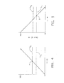
- FIG. 4 An example of the system's operation is illustrated in Figures 4 and 5.
- the speed N1 of the LPT shaft 26 is plotted as a function of time t.
- Figure 4 shows an accelerating condition as shown by the increase of N1 with increasing time.
- a critical speed Fn 0 of the LPT shaft 26, for example the first bending critical speed, is shown as a horizontal line.
- the shaft speed N1 would coincide with the critical speed Fn 0 at the point labeled A.
- the LPT shaft 26 would experience increased vibration, deflection, and stresses which could result in severe damage or destruction thereof.
- the support stiffness of one or both of the variable stiffness support means 76 and 110 is modified, for example by reducing their stiffness to a low value, possibly near zero. This reduces the critical speed to a modified value, denoted by the line Fn 1 .
- the amount of change in the critical speed, denoted ⁇ is controlled by the amount of change in the shaft end conditions C and the effective shaft length L. In this condition, the actual shaft speed no longer coincides with the critical speed.
- Figure 5 is generally similar to Figure 4, except that Figure 5 shows a decelerating condition as shown by the decrease of N1 with increasing time.
- the modified critical speed Fn 1 of the LPT shaft 26 is shown as a solid horizontal line. If the modified critical speed Fn 1 were left unchanged, the shaft speed N1 would coincide with the modified critical speed Fn 1 at the point labeled B. Under this condition, the LPT shaft 26 would experience increasing vibration, deflection, and stresses which could result in severe damage or destruction thereof. Accordingly, when the shaft speed N1 approaches the modified first bending critical speed Fn 1 , the support stiffness of one or both of the variable stiffness support means 76 and 110 is changed back to its unmodified (stiffer) value. This increases the critical speed to its baseline value Fn 0 , denoted by a horizontal dashed line. Again, the actual shaft speed does not coincide with the critical speed.
- a system for changing the critical speed of a shaft that includes: a first shaft supported for relative rotational movement with respect to a stationary structure, a forward bearing disposed at the forward end of the shaft, an aft bearing disposed at the aft end of the shaft, at least one active bearing disposed between the forward bearing and the aft bearing, and means for changing the support stiffness of the active bearing.
Landscapes
- Engineering & Computer Science (AREA)
- General Engineering & Computer Science (AREA)
- Mechanical Engineering (AREA)
- Chemical & Material Sciences (AREA)
- Combustion & Propulsion (AREA)
- Rolling Contact Bearings (AREA)
- Support Of The Bearing (AREA)
- Magnetic Bearings And Hydrostatic Bearings (AREA)
Abstract
Description
Claims (10)
- A system for changing the critical speed of a shaft, comprising:a first shaft (26) supported for relative rotational movement with respect to a stationary structure, said shaft having forward and aft ends, a first diameter, and a first length;a forward bearing (34) disposed at said forward end of said shaft,an aft bearing (40) disposed at said aft end of said shaft;a first active bearing (36) disposed between said forward bearing (34) and said aft bearing (40); andmeans for changing the support stiffness of said first active bearing (36).
- A system for changing the critical speed of a gas turbine engine shaft, comprising:a turbine shaft supported for relative rotational movement with respect to a stationary structure, said turbine shaft having forward and aft ends, a first diameter, and a first length;a forward bearing (34) disposed at said forward end of said turbine shaft,an aft bearing (40) disposed at said aft end of said turbine shaft;a first active bearing (36) disposed between said forward bearing (34) and said aft bearing (40); andmeans for changing the support stiffness of said first active bearing (36).
- The system of claim 1 or claim 2 wherein said means for changing the support stiffness of said first active bearing (36) comprise a first fluid film damper disposed between said first active bearing (36) and said stationary structure and means for selectively supplying fluid to said first fluid film damper.
- The system of claim 1 or claim 2 further comprising:a second active bearing (42) disposed between said first active bearing (36) and said aft bearing (40); andmeans for changing the support stiffness of said second active bearing (42).
- The system of claim 4 wherein said means for changing the support stiffness of said second active bearing (42) comprise a second fluid film damper disposed between said second active bearing (42) and said stationary structure and means for selectively supplying fluid to said second fluid film damper.
- The system of claim 1 or claim 2 further comprising a second shaft (28) having forward and aft ends mounted coaxially with said first shaft (26), said second shaft (28) having a second diameter greater than said first diameter and a second length shorter than said first length, wherein said first active bearing (36) is disposed between said forward bearing (34) and said forward end of said second shaft (28).
- The system of claim 6 wherein said means for changing the support stiffness of said first active bearing (36) comprise a first fluid film damper disposed between said first active bearing (36) and said stationary structure and means for selectively supplying fluid to said first fluid film damper.
- A method for changing the critical speed of a shaft, comprising:providing a shaft having forward and aft ends supported for relative rotational movement with respect to a stationary structure;providing a forward bearing (34) disposed at said forward end of said shaft,providing an aft bearing (40) disposed at said aft end of said shaft;providing a first active bearing (36) disposed between said forward bearing (34) and said aft bearing (40); andchanging the support stiffness of said first active bearing (36).
- The method for changing the critical speed of shaft of claim 8 wherein said means for changing the support stiffness of said first active bearing (36) comprise a first fluid film damper disposed between said first active bearing (36) and said stationary structure and means for selectively supplying fluid to said first fluid film damper.
- The method for changing the critical speed of a shaft of claim 8 further comprising:providing a second active bearing (42) disposed between said first active bearing (36) and said aft bearing (40); andproviding means for changing the support stiffness of said second active bearing (42).
Applications Claiming Priority (2)
| Application Number | Priority Date | Filing Date | Title |
|---|---|---|---|
| US236853 | 1994-05-02 | ||
| US10/236,853 US6846158B2 (en) | 2002-09-06 | 2002-09-06 | Method and apparatus for varying the critical speed of a shaft |
Publications (2)
| Publication Number | Publication Date |
|---|---|
| EP1396611A2 true EP1396611A2 (en) | 2004-03-10 |
| EP1396611A3 EP1396611A3 (en) | 2005-11-16 |
Family
ID=31715326
Family Applications (1)
| Application Number | Title | Priority Date | Filing Date |
|---|---|---|---|
| EP03255385A Withdrawn EP1396611A3 (en) | 2002-09-06 | 2003-08-29 | Method and apparatus for varying the critical speed of a shaft |
Country Status (3)
| Country | Link |
|---|---|
| US (1) | US6846158B2 (en) |
| EP (1) | EP1396611A3 (en) |
| JP (1) | JP4705750B2 (en) |
Cited By (32)
| Publication number | Priority date | Publication date | Assignee | Title |
|---|---|---|---|---|
| WO2010119115A1 (en) * | 2009-04-17 | 2010-10-21 | Snecma | Double-body gas turbine engine provided with an inter-shaft bearing |
| EP1703085A3 (en) * | 2005-03-14 | 2012-03-21 | Rolls-Royce Plc | A multi-shaft arrangement for a turbine engine |
| CN102418741A (en) * | 2011-08-12 | 2012-04-18 | 东华大学 | A rotor system that can actively adjust the critical speed of a variable-speed working rotor |
| EP1799969A4 (en) * | 2004-10-06 | 2013-05-01 | Volvo Aero Corp | A bearing support structure and a gas turbine engine comprising the bearing support structure |
| WO2013066995A1 (en) * | 2011-11-01 | 2013-05-10 | General Electric Company | Series bearing support apparatus for a gas turbine engine |
| EP2809890A4 (en) * | 2012-01-31 | 2015-11-04 | United Technologies Corp | BEARING ARRANGEMENT FOR GAS TURBINE ENGINE |
| EP3106685A1 (en) * | 2015-06-18 | 2016-12-21 | United Technologies Corporation | Bearing support damping |
| EP3179084A1 (en) * | 2015-12-11 | 2017-06-14 | General Electric Company | Gas turbine engine |
| EP3205843A1 (en) * | 2016-02-12 | 2017-08-16 | United Technologies Corporation | Method of bowed rotor start response damping, corresponding bowed rotor start response damping system and gas turbine engine |
| US10040577B2 (en) | 2016-02-12 | 2018-08-07 | United Technologies Corporation | Modified start sequence of a gas turbine engine |
| US10125636B2 (en) | 2016-02-12 | 2018-11-13 | United Technologies Corporation | Bowed rotor prevention system using waste heat |
| US10125691B2 (en) | 2016-02-12 | 2018-11-13 | United Technologies Corporation | Bowed rotor start using a variable position starter valve |
| US10174678B2 (en) | 2016-02-12 | 2019-01-08 | United Technologies Corporation | Bowed rotor start using direct temperature measurement |
| CN109833982A (en) * | 2019-04-08 | 2019-06-04 | 中国工程物理研究院总体工程研究所 | A kind of geotechnique's drum centrifuge device |
| US10358936B2 (en) | 2016-07-05 | 2019-07-23 | United Technologies Corporation | Bowed rotor sensor system |
| US10443505B2 (en) | 2016-02-12 | 2019-10-15 | United Technologies Corporation | Bowed rotor start mitigation in a gas turbine engine |
| US10443507B2 (en) | 2016-02-12 | 2019-10-15 | United Technologies Corporation | Gas turbine engine bowed rotor avoidance system |
| US10508601B2 (en) | 2016-02-12 | 2019-12-17 | United Technologies Corporation | Auxiliary drive bowed rotor prevention system for a gas turbine engine |
| US10508567B2 (en) | 2016-02-12 | 2019-12-17 | United Technologies Corporation | Auxiliary drive bowed rotor prevention system for a gas turbine engine through an engine accessory |
| US10539079B2 (en) | 2016-02-12 | 2020-01-21 | United Technologies Corporation | Bowed rotor start mitigation in a gas turbine engine using aircraft-derived parameters |
| US10801371B2 (en) | 2016-02-12 | 2020-10-13 | Raytheon Technologies Coproration | Bowed rotor prevention system |
| EP3839232A1 (en) * | 2019-12-19 | 2021-06-23 | Rolls-Royce plc | Gas turbine engine with a three bearings shaft |
| EP3839230A1 (en) * | 2019-12-19 | 2021-06-23 | Rolls-Royce plc | Shaft bearings with improved stiffness |
| EP3839211A1 (en) * | 2019-12-19 | 2021-06-23 | Rolls-Royce plc | Gas turbine engine with shaft bearings |
| EP3839231A1 (en) * | 2019-12-19 | 2021-06-23 | Rolls-Royce plc | Gas turbine engine with reduced vibrations |
| EP3839229A1 (en) * | 2019-12-19 | 2021-06-23 | Rolls-Royce plc | Gas turbine engine with improved resonance response |
| EP3854997A1 (en) * | 2019-12-19 | 2021-07-28 | Rolls-Royce plc | Improved turbine positioning in a gas turbine engine |
| US11268441B2 (en) | 2019-12-19 | 2022-03-08 | Rolls-Royce Plc | Shaft bearing arrangement |
| RU226127U1 (en) * | 2023-09-28 | 2024-05-21 | Акционерное Общество "Гт Энерго" | GAS TURBINE PLANT |
| FR3145582A1 (en) * | 2023-02-07 | 2024-08-09 | Safran Helicopter Engines | Device for centering and guiding the rotation of a shaft line of a turbomachine and turbomachine |
| EP3712393B1 (en) * | 2019-03-19 | 2024-11-06 | Rolls-Royce plc | Gas turbine engine with bearing support structure |
| EP3430242B1 (en) * | 2016-03-15 | 2025-01-01 | Safran Aircraft Engines | Turbojet engine comprising a simplified bearing lubrication unit |
Families Citing this family (39)
| Publication number | Priority date | Publication date | Assignee | Title |
|---|---|---|---|---|
| FR2866069A1 (en) * | 2004-02-06 | 2005-08-12 | Snecma Moteurs | SOLIDARITY BLOWER TURBOREACTOR OF A DRIVE SHAFT SUPPORTED BY A FIRST AND A SECOND BEARING |
| FR2866068B1 (en) * | 2004-02-06 | 2006-07-07 | Snecma Moteurs | SOLIDARITY BLOWER TURBOREACTOR OF A DRIVE SHAFT SUPPORTED BY A FIRST AND A SECOND BEARING |
| FR2877398B1 (en) * | 2004-10-28 | 2009-10-30 | Snecma Moteurs Sa | ROTARY MOTOR WITH TWO RAISEURS TREE BEARING |
| US7685808B2 (en) | 2005-10-19 | 2010-03-30 | General Electric Company | Gas turbine engine assembly and methods of assembling same |
| JP2007127006A (en) * | 2005-11-02 | 2007-05-24 | Hitachi Ltd | A two-shaft gas turbine, a two-shaft gas turbine operation method, a two-shaft gas turbine control method, and a two-shaft gas turbine bearing cooling method. |
| US7841165B2 (en) * | 2006-10-31 | 2010-11-30 | General Electric Company | Gas turbine engine assembly and methods of assembling same |
| US8511986B2 (en) * | 2007-12-10 | 2013-08-20 | United Technologies Corporation | Bearing mounting system in a low pressure turbine |
| US8511055B2 (en) * | 2009-05-22 | 2013-08-20 | United Technologies Corporation | Apparatus and method for providing damper liquid in a gas turbine |
| US8176725B2 (en) * | 2009-09-09 | 2012-05-15 | United Technologies Corporation | Reversed-flow core for a turbofan with a fan drive gear system |
| FR2951232B1 (en) * | 2009-10-08 | 2017-06-09 | Snecma | DEVICE FOR CENTERING AND GUIDING ROTATION OF A TURBOMACHINE SHAFT |
| WO2011044432A2 (en) * | 2009-10-09 | 2011-04-14 | Dresser-Rand Company | Auxiliary bearing system with plurality of inertia rings for magnetically supported rotor system |
| EP2486292B1 (en) * | 2009-10-09 | 2017-08-09 | Dresser-Rand Company | Auxiliary bearing system for magnetically supported rotor system |
| US8465207B2 (en) * | 2009-10-09 | 2013-06-18 | Dresser-Rand Company | Auxiliary bearing system with oil reservoir for magnetically supported rotor system |
| US8408806B2 (en) * | 2009-10-09 | 2013-04-02 | Dresser-Rand Company | Auxiliary bearing system with oil ring for magnetically supported rotor system |
| WO2011088004A2 (en) | 2010-01-15 | 2011-07-21 | Dresser-Rand Company | Bearing assembly support and adjustment system |
| US8845277B2 (en) | 2010-05-24 | 2014-09-30 | United Technologies Corporation | Geared turbofan engine with integral gear and bearing supports |
| EP2659277B8 (en) | 2010-12-30 | 2018-05-23 | Dresser-Rand Company | Method for on-line detection of resistance-to-ground faults in active magnetic bearing systems |
| US8994237B2 (en) | 2010-12-30 | 2015-03-31 | Dresser-Rand Company | Method for on-line detection of liquid and potential for the occurrence of resistance to ground faults in active magnetic bearing systems |
| US9551349B2 (en) | 2011-04-08 | 2017-01-24 | Dresser-Rand Company | Circulating dielectric oil cooling system for canned bearings and canned electronics |
| US9188105B2 (en) | 2011-04-19 | 2015-11-17 | Hamilton Sundstrand Corporation | Strut driveshaft for ram air turbine |
| US8876389B2 (en) | 2011-05-27 | 2014-11-04 | Dresser-Rand Company | Segmented coast-down bearing for magnetic bearing systems |
| US8851756B2 (en) | 2011-06-29 | 2014-10-07 | Dresser-Rand Company | Whirl inhibiting coast-down bearing for magnetic bearing systems |
| US20130340435A1 (en) * | 2012-01-31 | 2013-12-26 | Gregory M. Savela | Gas turbine engine aft spool bearing arrangement and hub wall configuration |
| US10145266B2 (en) * | 2012-01-31 | 2018-12-04 | United Technologies Corporation | Gas turbine engine shaft bearing arrangement |
| US9476320B2 (en) | 2012-01-31 | 2016-10-25 | United Technologies Corporation | Gas turbine engine aft bearing arrangement |
| US10001028B2 (en) | 2012-04-23 | 2018-06-19 | General Electric Company | Dual spring bearing support housing |
| FR3000150B1 (en) * | 2012-12-21 | 2015-06-05 | Snecma | BEARING BEARING AND AXIAL LOCKING SYSTEM OF SAID BEARING BEARING |
| US20160047335A1 (en) * | 2014-08-15 | 2016-02-18 | General Electric Company | Mechanical drive architectures with mono-type low-loss bearings and low-density materials |
| GB201421881D0 (en) | 2014-12-09 | 2015-01-21 | Rolls Royce Plc | Bearing structure |
| GB201421880D0 (en) * | 2014-12-09 | 2015-01-21 | Rolls Royce Plc | Bearing structure |
| CA2934668C (en) * | 2015-07-09 | 2018-11-06 | General Electric Company | Bearing assembly for supporting a rotor shaft of a gas turbine engine |
| US10094283B2 (en) | 2015-10-28 | 2018-10-09 | General Electric Company | Differential gas bearing for aircraft engines |
| FR3049008B1 (en) | 2016-03-15 | 2018-03-02 | Safran Aircraft Engines | TURBOREACTOR COMPRISING A LOWER SUPERCRITICAL PRESSURE TREE |
| GB201704502D0 (en) * | 2017-03-22 | 2017-05-03 | Rolls Royce Plc | Gas turbine engine |
| FR3085436B1 (en) * | 2018-08-28 | 2021-05-14 | Safran Aircraft Engines | TURBOMACHINE WITH AXIAL DRAWBACK AT A BEARING LEVEL |
| US10844745B2 (en) * | 2019-03-29 | 2020-11-24 | Pratt & Whitney Canada Corp. | Bearing assembly |
| US11268405B2 (en) | 2020-03-04 | 2022-03-08 | Pratt & Whitney Canada Corp. | Bearing support structure with variable stiffness |
| US11492926B2 (en) | 2020-12-17 | 2022-11-08 | Pratt & Whitney Canada Corp. | Bearing housing with slip joint |
| US12392371B2 (en) * | 2023-07-19 | 2025-08-19 | Unison Industries, Llc | Air turbine starter with fluid damping assembly |
Family Cites Families (15)
| Publication number | Priority date | Publication date | Assignee | Title |
|---|---|---|---|---|
| FR2336550A1 (en) * | 1975-12-24 | 1977-07-22 | Europ Propulsion | LONG SHAFT MOUNTING, ESPECIALLY FOR TURBOMACHINE |
| US4457667A (en) * | 1980-12-11 | 1984-07-03 | United Technologies Corporation | Viscous damper with rotor centering means |
| US4737655A (en) | 1986-06-26 | 1988-04-12 | General Electric Company | Prime mover control |
| JPS63235715A (en) * | 1987-03-23 | 1988-09-30 | Mitsubishi Heavy Ind Ltd | Vibration damping type bearing device for rotary machine |
| US5603574A (en) | 1987-05-29 | 1997-02-18 | Kmc, Inc. | Fluid dampened support having variable stiffness and damping |
| JP2508506Y2 (en) * | 1988-03-08 | 1996-08-28 | 三菱重工業株式会社 | Vibration suppression device for rotating machinery |
| US4867655A (en) | 1988-03-14 | 1989-09-19 | United Technologies Corporation | Variable stiffness oil film damper |
| US4983051A (en) * | 1988-05-12 | 1991-01-08 | United Technologies Corporation | Apparatus for supporting a rotating shaft in a rotary machine |
| US4947639A (en) * | 1988-05-12 | 1990-08-14 | United Technologies Corporation | Apparatus and method for supporting a rotating shaft in a rotary machine |
| US5110257A (en) | 1988-05-12 | 1992-05-05 | United Technologies Corporation | Apparatus for supporting a rotating shaft in a rotary machine |
| US5347190A (en) * | 1988-09-09 | 1994-09-13 | University Of Virginia Patent Foundation | Magnetic bearing systems |
| JP2572530B2 (en) * | 1993-08-30 | 1997-01-16 | 川崎重工業株式会社 | Vibration spectrum monitoring device, and health monitoring method and device |
| US5374129A (en) | 1994-03-15 | 1994-12-20 | General Electric Co. | Hydrostatic bearing support affording high static and low dynamic stiffness to a rotor in turbomachinery |
| US5452957A (en) | 1994-11-22 | 1995-09-26 | Dana Corporation | Center bearing assembly including support member containing rheological fluid |
| US6554754B2 (en) * | 2000-06-28 | 2003-04-29 | Appleton International, Inc. | “Smart” bowed roll |
-
2002
- 2002-09-06 US US10/236,853 patent/US6846158B2/en not_active Expired - Fee Related
-
2003
- 2003-08-29 EP EP03255385A patent/EP1396611A3/en not_active Withdrawn
- 2003-09-05 JP JP2003313349A patent/JP4705750B2/en not_active Expired - Fee Related
Cited By (54)
| Publication number | Priority date | Publication date | Assignee | Title |
|---|---|---|---|---|
| EP1799969A4 (en) * | 2004-10-06 | 2013-05-01 | Volvo Aero Corp | A bearing support structure and a gas turbine engine comprising the bearing support structure |
| EP1703085A3 (en) * | 2005-03-14 | 2012-03-21 | Rolls-Royce Plc | A multi-shaft arrangement for a turbine engine |
| US8919133B2 (en) | 2009-04-17 | 2014-12-30 | Snecma | Double-body gas turbine engine provided with an inter-shaft bearing |
| FR2944558A1 (en) * | 2009-04-17 | 2010-10-22 | Snecma | DOUBLE BODY GAS TURBINE ENGINE PROVIDED WITH SUPPLEMENTARY BP TURBINE BEARING. |
| WO2010119115A1 (en) * | 2009-04-17 | 2010-10-21 | Snecma | Double-body gas turbine engine provided with an inter-shaft bearing |
| CN102418741A (en) * | 2011-08-12 | 2012-04-18 | 东华大学 | A rotor system that can actively adjust the critical speed of a variable-speed working rotor |
| CN104011335B (en) * | 2011-11-01 | 2016-05-04 | 通用电气公司 | For the series connection bearing supporting device of gas-turbine unit |
| WO2013066995A1 (en) * | 2011-11-01 | 2013-05-10 | General Electric Company | Series bearing support apparatus for a gas turbine engine |
| US8727629B2 (en) | 2011-11-01 | 2014-05-20 | General Electric Company | Series bearing support apparatus for a gas turbine engine |
| CN104011335A (en) * | 2011-11-01 | 2014-08-27 | 通用电气公司 | Series bearing support apparatus for a gas turbine engine |
| EP2809890A4 (en) * | 2012-01-31 | 2015-11-04 | United Technologies Corp | BEARING ARRANGEMENT FOR GAS TURBINE ENGINE |
| EP3779129A1 (en) * | 2012-01-31 | 2021-02-17 | Raytheon Technologies Corporation | Gas turbine engine bearing arrangement |
| EP3106685A1 (en) * | 2015-06-18 | 2016-12-21 | United Technologies Corporation | Bearing support damping |
| US9714584B2 (en) | 2015-06-18 | 2017-07-25 | United Technologies Corporation | Bearing support damping |
| EP3179084A1 (en) * | 2015-12-11 | 2017-06-14 | General Electric Company | Gas turbine engine |
| CN106870202A (en) * | 2015-12-11 | 2017-06-20 | 通用电气公司 | Gas-turbine unit |
| US10508567B2 (en) | 2016-02-12 | 2019-12-17 | United Technologies Corporation | Auxiliary drive bowed rotor prevention system for a gas turbine engine through an engine accessory |
| US10787277B2 (en) | 2016-02-12 | 2020-09-29 | Raytheon Technologies Corporation | Modified start sequence of a gas turbine engine |
| US10125691B2 (en) | 2016-02-12 | 2018-11-13 | United Technologies Corporation | Bowed rotor start using a variable position starter valve |
| US10174678B2 (en) | 2016-02-12 | 2019-01-08 | United Technologies Corporation | Bowed rotor start using direct temperature measurement |
| US10125636B2 (en) | 2016-02-12 | 2018-11-13 | United Technologies Corporation | Bowed rotor prevention system using waste heat |
| EP3205843A1 (en) * | 2016-02-12 | 2017-08-16 | United Technologies Corporation | Method of bowed rotor start response damping, corresponding bowed rotor start response damping system and gas turbine engine |
| US10436064B2 (en) | 2016-02-12 | 2019-10-08 | United Technologies Corporation | Bowed rotor start response damping system |
| US10443505B2 (en) | 2016-02-12 | 2019-10-15 | United Technologies Corporation | Bowed rotor start mitigation in a gas turbine engine |
| US10443507B2 (en) | 2016-02-12 | 2019-10-15 | United Technologies Corporation | Gas turbine engine bowed rotor avoidance system |
| US10508601B2 (en) | 2016-02-12 | 2019-12-17 | United Technologies Corporation | Auxiliary drive bowed rotor prevention system for a gas turbine engine |
| US10040577B2 (en) | 2016-02-12 | 2018-08-07 | United Technologies Corporation | Modified start sequence of a gas turbine engine |
| US10539079B2 (en) | 2016-02-12 | 2020-01-21 | United Technologies Corporation | Bowed rotor start mitigation in a gas turbine engine using aircraft-derived parameters |
| US10625881B2 (en) | 2016-02-12 | 2020-04-21 | United Technologies Corporation | Modified start sequence of a gas turbine engine |
| US11274604B2 (en) | 2016-02-12 | 2022-03-15 | Raytheon Technologies Corporation | Bowed rotor start mitigation in a gas turbine engine using aircraft-derived parameters |
| US10801371B2 (en) | 2016-02-12 | 2020-10-13 | Raytheon Technologies Coproration | Bowed rotor prevention system |
| EP3430242B1 (en) * | 2016-03-15 | 2025-01-01 | Safran Aircraft Engines | Turbojet engine comprising a simplified bearing lubrication unit |
| US10358936B2 (en) | 2016-07-05 | 2019-07-23 | United Technologies Corporation | Bowed rotor sensor system |
| EP3712393B1 (en) * | 2019-03-19 | 2024-11-06 | Rolls-Royce plc | Gas turbine engine with bearing support structure |
| CN109833982B (en) * | 2019-04-08 | 2024-01-30 | 中国工程物理研究院总体工程研究所 | Geotechnical drum type centrifuge device |
| CN109833982A (en) * | 2019-04-08 | 2019-06-04 | 中国工程物理研究院总体工程研究所 | A kind of geotechnique's drum centrifuge device |
| EP3839231A1 (en) * | 2019-12-19 | 2021-06-23 | Rolls-Royce plc | Gas turbine engine with reduced vibrations |
| US11732649B2 (en) | 2019-12-19 | 2023-08-22 | Rolls-Royce Plc | Shaft bearing positioning in a gas turbine engine |
| US11193423B2 (en) | 2019-12-19 | 2021-12-07 | Rolls-Royce Plc | Shaft bearings |
| US11203971B2 (en) | 2019-12-19 | 2021-12-21 | Rolls-Royce Plc | Turbine positioning in a gas turbine engine |
| US11248493B2 (en) | 2019-12-19 | 2022-02-15 | Rolls-Royce Plc | Gas turbine engine with a three bearings shaft |
| US11268441B2 (en) | 2019-12-19 | 2022-03-08 | Rolls-Royce Plc | Shaft bearing arrangement |
| EP3839229A1 (en) * | 2019-12-19 | 2021-06-23 | Rolls-Royce plc | Gas turbine engine with improved resonance response |
| US11333072B2 (en) | 2019-12-19 | 2022-05-17 | Rolls-Royce Plc | Shaft bearing positioning in a gas turbine engine |
| US11448164B2 (en) | 2019-12-19 | 2022-09-20 | Rolls-Royce Plc | Shaft bearings for gas turbine engine |
| EP3854997A1 (en) * | 2019-12-19 | 2021-07-28 | Rolls-Royce plc | Improved turbine positioning in a gas turbine engine |
| EP3839211A1 (en) * | 2019-12-19 | 2021-06-23 | Rolls-Royce plc | Gas turbine engine with shaft bearings |
| EP3839232A1 (en) * | 2019-12-19 | 2021-06-23 | Rolls-Royce plc | Gas turbine engine with a three bearings shaft |
| EP3839230A1 (en) * | 2019-12-19 | 2021-06-23 | Rolls-Royce plc | Shaft bearings with improved stiffness |
| US12049846B2 (en) | 2019-12-19 | 2024-07-30 | Rolls-Royce Plc | Shaft bearing positioning in a gas turbine engine |
| FR3145582A1 (en) * | 2023-02-07 | 2024-08-09 | Safran Helicopter Engines | Device for centering and guiding the rotation of a shaft line of a turbomachine and turbomachine |
| WO2024165810A1 (en) * | 2023-02-07 | 2024-08-15 | Safran Helicopter Engines | Device for centring and rotationally guiding a shaft line of a turbomachine, and turbomachine |
| RU226126U1 (en) * | 2023-09-19 | 2024-05-21 | Акционерное Общество "Гт Энерго" | GAS TURBINE PLANT |
| RU226127U1 (en) * | 2023-09-28 | 2024-05-21 | Акционерное Общество "Гт Энерго" | GAS TURBINE PLANT |
Also Published As
| Publication number | Publication date |
|---|---|
| US6846158B2 (en) | 2005-01-25 |
| US20040047731A1 (en) | 2004-03-11 |
| JP4705750B2 (en) | 2011-06-22 |
| EP1396611A3 (en) | 2005-11-16 |
| JP2004263854A (en) | 2004-09-24 |
Similar Documents
| Publication | Publication Date | Title |
|---|---|---|
| US6846158B2 (en) | Method and apparatus for varying the critical speed of a shaft | |
| JP2823588B2 (en) | Method and apparatus for supporting rotating shaft in rotating device | |
| US5658125A (en) | Magnetic bearings as actuation for active compressor stability control | |
| EP3763930B1 (en) | Gas turbine engine electrical generator | |
| EP3106685B1 (en) | Bearing support damping | |
| US6582125B1 (en) | Smart foil journal bearing with piezoelectric actuators | |
| US5974782A (en) | Method for enabling operation of an aircraft turbo-engine with rotor unbalance | |
| US7524112B2 (en) | Bearing support with double stiffener | |
| CA3024506C (en) | Turbine bearing support | |
| JP5956290B2 (en) | Gas turbine engine including a broadband damping system and method of manufacturing the same | |
| KR101313927B1 (en) | Radial bearing | |
| EP3392515B1 (en) | Bearing arrangement | |
| CA2937018A1 (en) | Magnetic squeeze film damper system for a gas turbine engine | |
| EP3693632B1 (en) | Optimizing squeeze film damper performance using entrained gas | |
| EP3854997A1 (en) | Improved turbine positioning in a gas turbine engine | |
| GB2173867A (en) | Bearing supports | |
| JPH0781588B2 (en) | Bearing support | |
| EP3839211A1 (en) | Gas turbine engine with shaft bearings | |
| US20160084301A1 (en) | Rotating machinery with adaptive bearing journals and methods of operating | |
| JPH0814256A (en) | Hydrostatic bearing support for rotors | |
| JP4154134B2 (en) | Shaft support structure for rotating electrical machines | |
| US10746050B2 (en) | Variable stiffness bearing suspension device | |
| US11698027B2 (en) | System for vibration management in rotating machinery | |
| EP3839230A1 (en) | Shaft bearings with improved stiffness | |
| EP4522877A1 (en) | A method and an apparatus to reduce shaft deformation |
Legal Events
| Date | Code | Title | Description |
|---|---|---|---|
| PUAI | Public reference made under article 153(3) epc to a published international application that has entered the european phase |
Free format text: ORIGINAL CODE: 0009012 |
|
| AK | Designated contracting states |
Kind code of ref document: A2 Designated state(s): AT BE BG CH CY CZ DE DK EE ES FI FR GB GR HU IE IT LI LU MC NL PT RO SE SI SK TR |
|
| AX | Request for extension of the european patent |
Extension state: AL LT LV MK |
|
| PUAL | Search report despatched |
Free format text: ORIGINAL CODE: 0009013 |
|
| AK | Designated contracting states |
Kind code of ref document: A3 Designated state(s): AT BE BG CH CY CZ DE DK EE ES FI FR GB GR HU IE IT LI LU MC NL PT RO SE SI SK TR |
|
| AX | Request for extension of the european patent |
Extension state: AL LT LV MK |
|
| RIC1 | Information provided on ipc code assigned before grant |
Ipc: 7F 01D 5/02 B Ipc: 7F 02C 7/06 B Ipc: 7F 01D 25/16 A |
|
| 17P | Request for examination filed |
Effective date: 20060516 |
|
| AKX | Designation fees paid |
Designated state(s): DE FR GB IT |
|
| 17Q | First examination report despatched |
Effective date: 20071010 |
|
| STAA | Information on the status of an ep patent application or granted ep patent |
Free format text: STATUS: THE APPLICATION IS DEEMED TO BE WITHDRAWN |
|
| 18D | Application deemed to be withdrawn |
Effective date: 20150303 |